TIRE PRESSURE WARNING SYSTEM DETAILS
-
FUNCTION OF MAIN COMPONENTS
Component Function Tire Pressure Warning Valve and Transmitter Detects the tire inflation pressure and temperature of the tire and transmits the measured value and ID code to the tire pressure warning ECU and receiver. Tire Pressure Warning ECU and Receiver
-
Receives the data from each tire pressure warning valve and transmitter and monitors its tire inflation pressure.
-
Outputs the respective signal to the main body ECU (multiplex network body ECU) when a drop in the tire inflation pressure, a system malfunction or the beginning of initialization is detected.
Main Body ECU (Multiplex Network Body ECU) Receives the signal from the tire pressure warning ECU and receiver and outputs it to the combination meter assembly via CAN communication. Speed Sensor* Detect the wheel speed pulse count of each of the 4 wheels and sends the 4 wheel speed pulse count signal to skid control ECU. Brake Booster with Master Cylinder* Skid Control ECU* Transmits the 4 wheel speed signal to the tire pressure warning ECU and receiver. Combination Meter Assembly Transmits the vehicle speed signal to the tire pressure warning ECU and receiver. Combination Meter Assembly Tire Pressure Warning Light Warns the driver by illuminating or blinking for one minute in accordance with the signal from the tire pressure warning ECU and receiver. Multi-information display* Displays the identified tire pressure and position to inform or warn the driver. Steering Pad Switch Assembly* DISP Switch Switches the information on the multi-information display to the tire pressure when pressed. *: Models with tire inflation pressure display function
-
-
FUNCTION
-
Tire Inflation Pressure Display Function (Models with Tire Inflation Pressure Display Function)
-
The multi-information display shows the following to inform or warn the driver of the tire pressure:
Condition Multi-information Display Tire pressure is normal. 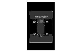
Tire pressure is below the warning threshold. 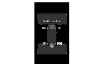
Tire position identification has not yet been completed. 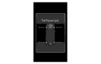
There is a system malfunction. 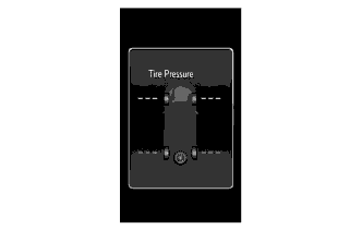
-
Identification of the tire position is carried out when the power switch is turned on (IG) or when initialization is performed. However, under certain conditions, the tire position may not be displayed. In that case, radio wave conditions may be restored by continuously driving, thereby enabling tire position determination.
-
Identification of tire located is completed by driving for about 10 minutes at 37 km/h (23.0 mph) or more. It updates the display of air pressure value at intervals of about 5 minutes or less.
-
-
Warning Function
-
The tire pressure warning system has 2 warning methods that are used, depending on the condition detected.
-
The table below shows the warning methods for the tire pressure warning light in the combination meter assembly and the multi-information display.
Detection Condition Tire Pressure Warning Light Multi-information Display The tire pressure warning system has detected that the tire pressure has become lower than the warning threshold. Illuminates*1 The tire pressure warning system has detected a malfunction in the system. Stays on after blinking for 1 minute*2 Tech Tips
-
*1: If the tire pressure warning light illuminates, adjust the tire pressure.
-
*2: If the tire pressure warning light stays on after blinking for 1 minute, the system is malfunctioning and must be repaired in order to turn off the light. For details, refer to the Repair Manual.
-
-
-
Initial Check Function
-
After the power switch is tuned to on, the tire pressure warning ECU and receiver illuminates the tire pressure warning light for 3 seconds to check the warning light circuits.
-
-
Initialization Function
-
The warning threshold and wheel position* is calculated from the tire inflation pressure valve and wheel speed sensor* at the time of initialization and memorized in the tire pressure warning ECU and receiver. Therefore, the tire pressure warning ECU and receiver should be initialized after:
-
The recommended tire inflation pressure changes due to changes in vehicle weight, speed conditions or tire size.
-
Replacement of the tire pressure warning ECU and receiver or a tire pressure warning valve and transmitter.
-
The tires are rotated.
-
The tire pressure is adjusted.
Tech Tips
*: Models with inflation pressure display function
-
-
-
-
CONSTRUCTION
-
Tire Pressure Warning Valve and Transmitter
-
The tire pressure warning valve and transmitters are integrated in the tire valves. Each transmitter consist of a lithium battery, sensor and transmitter.
-
Make sure not to damage the urethane covered backside of the transmitter (the surface opposite to the side with the ID code) with anything sharp.
-
The transmitter directly measures tire pressure, temperature, and centrifugal acceleration.
-
The transmitter transmits the measured tire inflation pressure and temperature values to the tire pressure warning ECU and receiver on a frequency of 314.98 MHz*1 or 433.90 MHz*2.
Tech Tips
*1: Except destination package for South Korea
*2: Destination package for South Korea
-
Depending on the timing of the data transmission, it may take several minutes to receive the data from the tire pressure warning valve and transmitter.
-
The ID code is written on the tire pressure warning valve and transmitter.
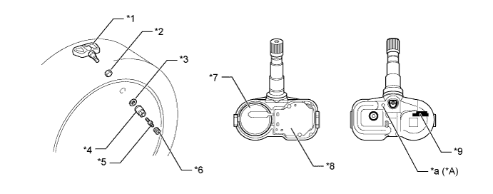
Text in Illustration *A Models with Tire Inflation Pressure Display Function - - *1 Tire Pressure Warning Valve and Transmitter *2 Grommet *3 Washer *4 Nut *5 Tire Valve Core *6 Cap *7 Lithium Battery *8 Sensor and Transmitter *9 ID Code (Hexadecimal 7 Digits) - - *a Identification Marking - - Tech Tips
-
The lithium batteries of the tire pressure warning valve and transmitters are non-replaceable. If a battery is depleted, the tire pressure warning valve and transmitter must be replaced. (Battery life: approximately 10 years)
-
When replacing a tire pressure warning valve and transmitter, each of the tire pressure warning valve and transmitter ID codes must be registered. If even one of the transmitters is replaced, the ID codes of all tire pressure warning valves and transmitters must be registered again. Record all the existing ID codes before beginning the process to enter new ID codes.
-
To register an ID code, use the Techstream to enter the ID code that is indicated on the tire pressure warning valve and transmitter.
-
Be careful not to damage the tire pressure warning valve and transmitters when removing and reinstalling them.
-
Replace the grommet and valve core with new ones when tire pressure warning valve and transmitter is being replaced or being replaced or being removed and reinstalled. This is necessary to ensure sealing performance.
-
When replacing a valve cap, use only the specified cap. If an unspecified cap is used, it may seize to the tire pressure warning valve and transmitter.
-
For details, refer to the Repair Manual.
-
-
-
-
DIAGNOSIS
-
To inform the driver when the tire pressure warning ECU and receiver detects a malfunction in the system, the tire pressure warning ECU and receiver will blink the tire pressure warning light for 1 minute, after which the light will illuminate. The tire pressure warning ECU and receiver will also store Diagnostic Trouble Codes (DTCs) in memory.
-
5-digit DTCs can be read by connecting the Techstream to the DLC3. For details, refer to the Repair Manual.
-