AIR CONDITIONING SYSTEM
-
SYSTEM CONTROL
-
The air conditioning system has the following controls:
Control Function Neural Network Control This control is capable of effecting complex control by artificially simulating the information processing method of the nervous system of living organisms in order to establish a complex input/output relationship that is similar to a human brain. Automatic Recirculation Control Automatically changes the air inlet mode to fresh air or recirculation air mode in accordance with the level of harmful elements in the outside air, the cabin temperature and outside temperature. Micro Dust and Pollen Filter Mode Control Activated by the micro dust and pollen filter mode switch operation, switches the air vent to the FACE mode, and sends air which has passed through the clean air filter to the area around the upper part of the bodies of the driver and front passenger. This air is filtered by the clean air filter in order to remove pollen. Outlet Air Temp. Control Based on the temperature set using the temperature control switch, the neural network control calculates the outlet air temperature based on the input signals from various sensors. The temperature settings for the driver, front passenger, rear passenger LH and RH*1 are controlled independently in order to provide separate vehicle interior temperatures for the right and left sides of the cabin. Thus, air conditioning that accommodates the occupants' preferences has been achieved. Blower Control Controls the blower motor in accordance with the airflow volume that has been calculated by the neural network control based on the input signals from various sensors. Air Outlet Control Automatically switches the air outlets in accordance with the outlet mode that has been calculated by the neural network control based on the input signals from various sensors. In accordance with the engine coolant temperature, outside air temperature, amount of sunlight, required blower, outlet temperature and vehicle speed conditions, this control automatically switches the blower outlet to FOOT/DEF mode to prevent the windows from becoming fogged when the outside air temperature is low. Air Inlet Control Automatically controls the air inlet control damper to achieve the calculated required outlet air temperature. Drives the servo motor (for air inlet) in accordance with the operation of the air inlet control switch and moves the dampers to the FRESH or RECIRC position. Compressor With Pulley Assembly Control Through the calculation of the target evaporator temperature based on various sensor signals, the air conditioning amplifier assembly optimally controls the discharge capacity by regulating the opening extent of the compressor with pulley assembly solenoid valve. PTC Heater Control*2 When the engine switch is on, and the blower motor is turned on, the air conditioning amplifier assembly turns on the PTC heater if the conditions listed below are met:
-
Engine coolant temperature is below the specified temperature.
-
Outside temperature is below the specified temperature.
-
Tentative air mix damper opening angle is above the specified value (MAX HOT).
Clean Air Filter Clogging Judgment Determines whether the clean air filter (for the front A/C) is clogged by monitoring the air inlets and airflow volume. Air Quality Control Improves the air quality by linking the air inlet control damper and the blower motor (for the rear A/C and air purifier), based on the signals from the smog ventilation sensor and the smoke sensor. Rear Window Defogger Control Switches the rear defogger and outside rear view mirror heaters on for 15 minutes when the rear defogger and mirror heater switch is pressed and switches them off if the button is pressed again while they are operating. Windshield Deicer Control*3 Switches the windshield deicer on for 15 minutes when the front wiper deicer switch is touched. Switches them off if the switch is pressed again while they are operating. Outside Temperature Indication Control Calculates the outside temperature using signals transmitted by the outside temperature sensor. Calculated values are corrected by the air conditioning amplifier assembly and then indicated on the multi-information display and the heater control panel. Load Control The electric power control ECU (passenger side junction block) sends the load control request signal to the air conditioning amplifier assembly depending on the condition of the battery. Upon receiving the signal, the air conditioning amplifier assembly temporarily limits the power consumption of the blower level, PTC heater and rear air conditioning. Seat Heater System Control On models with a seat heater system, the air conditioning amplifier assembly operates the seat heater system in accordance with the cabin conditions and the outside temperature. For details, see the Seat Heater System. Climate Control Seat System Control On models with a climate control seat system, the air conditioning amplifier assembly operates the climate control seat system in accordance with the cabin conditions and the outside temperature. For details, refer to the Climate Control Seat System. Steering Heater System Control On models with a steering heater system, the air conditioning amplifier assembly operates the steering heater system in accordance with the cabin conditions and the outside temperature. For details, see the Steering Heater System section. No. 1 Ion Generator Sub-assembly Control The No. 1 ion generator sub-assembly is controlled by the air conditioning amplifier assembly and operates when the [nanoe] switch is pressed and the blower is on. ECO Drive Mode Control An ECO drive mode is provided. In ECO drive mode, the air conditioning amplifier minimally adjusts the air conditioning under certain conditions in order to enhance fuel economy. Dehumidification Control*4 Operates the blower to blow a small amount of air according to the outside temperature, interior temperature and coolant temperature when the register mode is FOOT or FOOT/DEF to prevent glass fogging. Self-diagnosis A Diagnostic Trouble Code (DTC) is stored in the memory when the air conditioning amplifier assembly detects a problem with the air conditioning system. For details, refer to the Repair Manual.
-
*1: Models with multi-zone (4-zone) automatic climate control
-
*2: Models with quick heater assembly
-
*3: Models with front wiper deicer system
-
*4: Models for Europe
-
-
Neural Network Control
-
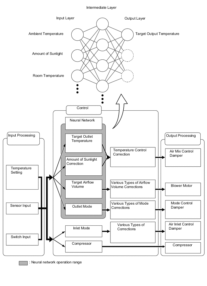
In previous automatic air conditioning systems, the air conditioning amplifier assembly determined the required outlet air temperature and blower air volume in accordance with the calculation formula that has been obtained based on information received from the sensors. However, because the senses of a person are rather complex, a given temperature is sensed differently, depending on the environment in which the person is situated. For example, a given amount of solar radiation can feel comfortably warm in a cold climate, or extremely uncomfortable in a hot climate. Therefore, as a technique for effecting a higher level of control, a neural network is used in the automatic air conditioning system. With this technique, the data that has been collected under varying environmental conditions is stored in the air conditioning amplifier assembly. The air conditioning amplifier assembly can then effect control to provide enhanced air conditioning comfort.
-
The neural network control consists of neurons in the input layer, intermediate layer and output layer. The input layer neurons process the input data of the outside temperature, the amount of sunlight, and the room temperature based on the outputs of the switches and sensors, and output them to the intermediate layer neurons. Based on this data, the intermediate layer neurons adjust the strength of the links among the neurons. The sum of these is then calculated by the output layer neurons in the form of the required outlet temperature, solar correction, target airflow volume and outlet mode control volume. Accordingly, the air conditioning amplifier assembly controls the servo motors and blower motor in accordance with the control volumes that have been calculated by the neural network control.
-
-
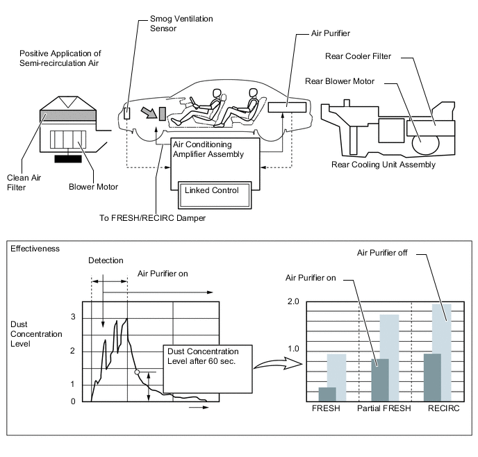
Automatic Recirculation Control
-
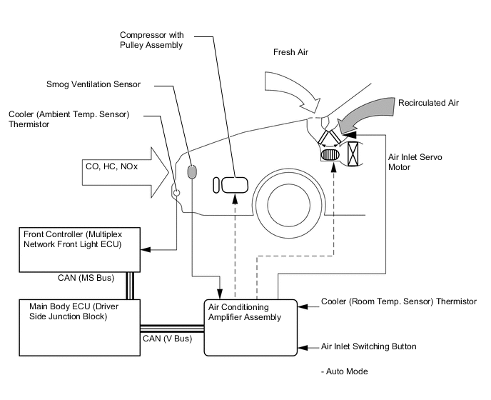
When the automatic recirculation control is operating, the air conditioning amplifier assembly automatically changes the air inlet mode to the fresh air or recirculate air mode based on signals from the smog ventilation sensor, cooler (ambient temp. sensor) thermistor and cooler (room temp. sensors) thermistor when the AUTO air inlet mode is selected.
-
The air conditioning amplifier assembly detects harmful elements (CO, HC and NOx) based on smog ventilation sensor signals and automatically switches the air inlet mode to the recirculate air mode to prevent such harmful elements from entering the cabin.
-
The air conditioning amplifier assembly detects room temperature based on a cooler (room temp. sensor) thermistor signal and automatically switches the air inlet mode to the recirculate air mode to prevent the room temperature from becoming too high.
-
The air conditioning amplifier assembly detects the outside temperature based on the cooler (ambient temp. sensor) thermistor signal and automatically switches the air inlet mode to the fresh air mode to prevent the windshield from fogging up.
Note
The smog ventilation sensor cannot detect elements such as the smoke from a bonfire or factory exhaust, foul or animal odors, and dirt or dust particles.
Therefore, the air inlet modes are not changed in accordance with those elements.
-
-
-
Micro Dust and Pollen Filter Mode Control
-
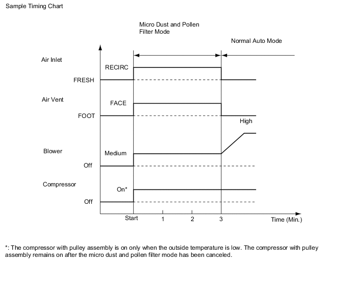
When the micro dust and pollen filter switch is pressed, the micro dust and pollen filter control is activated. Then, the air vent is switched to the FACE mode and recirculated pollen-free airflows in the area around the upper part of the bodies of the driver and front passenger.
-
When the micro dust and pollen filter switch signal is input to the air conditioning amplifier assembly, the air conditioning amplifier assembly controls the compressor with pulley assembly, air inlet servo motor, air vent servo motor and blower motor as shown in the timing chart below.
-
This control usually operates for approximately 3 minutes. However, when the outside temperature is low (5°C maximum), the control will operate for approximately 1 minute.
-
After this control stops operating, the air conditioning amplifier assembly controls the air conditioning system using the AUTO mode.
-
-
-
Clean Air Filter Clogging Judgment
-
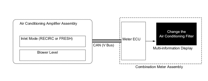
The airflow volume decreases when the filter becomes clogged, causing insufficient cooling or heating performance of the system. When the filter is clogged, the warning message is displayed on the multi-information display of the combination meter assembly to alert the driver to replace the clean air filter.
-
The air conditioning amplifier assembly transmits the signals to the meter ECU so as to display the message "Change the Air Conditioning Filter" on the multi-information display of the combination meter assembly once the air conditioning amplifier assembly calculates the airflow volume of the air outlet in accordance with the inlet mode and blower level and detects the blockage of the clean air filter.
-
-
Air Quality Control
-
This control, which is linked to the automatic recirculation control, operates the rear air conditioning and air purifier blower motor to improve the efficiency of the air purifier in order to supply the vehicle cabin with good quality air.
-
-
ECO Drive Mode Control
-
In ECO drive mode, the air conditioning amplifier assembly minimally adjusts air conditioning under certain conditions in order to enhance fuel economy.
-
When the ECO drive mode switch is on, the ECO MODE indicator illuminates. At this time, the air conditioning amplifier assembly limits air conditioning control in accordance with vehicle conditions as shown in the following table:
Mode Control Enhances fuel economy by automatically switching to the inlet mode for a certain period of time when the outside temperature is above approximately 20°C (68°F). Blower Control Suppresses electric power consumption by automatically controlling the air volume to approximately 80% less than normal while AUTO mode is on. Idle-up Control Enhances fuel economy by preventing idle-up control when cooling and heating. PTC Heater Control* Enhances fuel economy by preventing PTC heater control.
-
*: Models with quick heater assembly
-
-
-
-
CONSTRUCTION
-
Front Air Conditioning Control Panel (Heater Control Panel)
-
A push-button type heater control panel integrated with the multi-media module receiver assembly is used.
-
Temperature control switches for the driver and front passenger are provided on the heater control panel to enhance their ease of use.
-
The air conditioning status is displayed on the multi-display.
-
Preset temperatures for the driver seat and front passenger seat are also displayed on the organic electro luminescence display of the multi-media module receiver assembly.
-
In addition to the air conditioning control panel, the remote touch (remote operation switch) is used, ensuring remote control operation of items on the multi-display and allowing for excellent operability and display visibility.
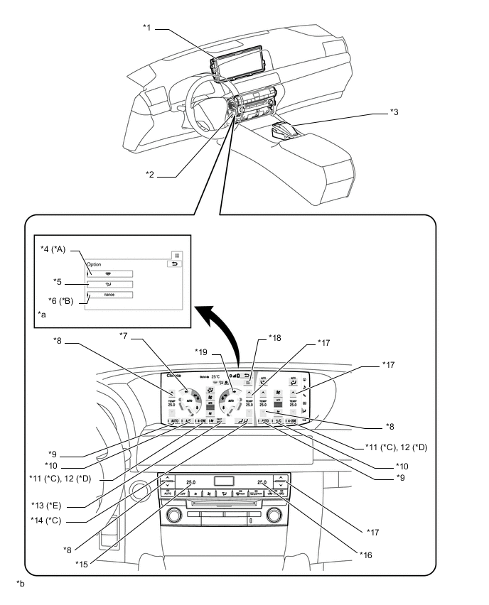
Text in Illustration *A Models with Windshield Deicer System *B Models with No. 1 Ion Generator Sub-assembly *C Models with Multi-zone (4-zone) Automatic Climate Control *D Models with Left and Right Independent Temperature Control *E Models with Blower Customization Control - - *1 Multi-display (Accessory Meter Assembly) *2 Multi-media Module Receiver Assembly *3 Remote Touch *4 Front Wiper Deicer Switch *5 Pollen Removal Mode Switch *6 [nanoe] Generator Switch *7 Air Outlet Mode Control Switch (Front LH Side) *8 Temperature Control Switch (Front LH Side) *9 Auto Switch *10 A/C Switch *11 4-ZONE Switch *12 DUAL Switch *13 FAST SOFT switch *14 Rear Control Mode Switch *15 Preset Temperature Display (Front LH Side) *16 Preset Temperature Display (Front RH Side) *17 Temperature Control Switch (Front RH Side) *18 Option Switch *19 Air Outlet Mode Control Switch (Front RH Side) - - *a Option Display *b The illustrations shown are examples only. The illustrations may differ from the actual vehicle screens.
-
-
Rear Air Conditioning Control Panel (Rear Power Seat Switch)
-
On models with rear air conditioning system, the set temperatures of both the seats and the operation mode of the rear air conditioning can be changed with the rear power seat switch.
-
On the Liquid Crystal Display (LCD) of the rear power seat switch, the set temperature status of the rear air conditioning status and both are displayed.
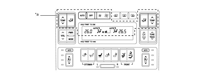
Text in Illustration *a Rear Air Conditioning Switch and Display Section - -
-
-
Front Air Conditioning Unit
-
A semi-center location air conditioning unit, in which the No. 1 cooler evaporator subassembly and heater radiator unit sub-assembly are placed in the vehicle's longitudinal direction, is used. As a result, the air conditioning unit has been made compact and lightweight.
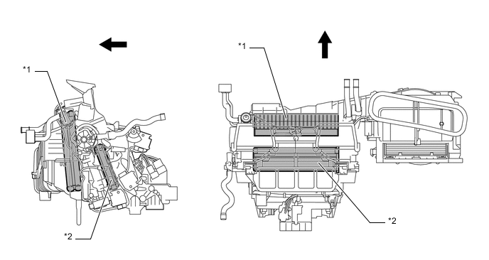
Text in Illustration *1 No. 1 Cooler Evaporator Sub-assembly *2 Heater Radiator Unit Sub-assembly 
Front - -
-
-
Heater Radiator Unit Sub-assembly
-
A compact, lightweight and highly efficient Straight Flow Aluminum (SFA)-II type heater radiator unit sub-assembly is used for the air conditioning system.

-
-
No. 1 Cooler Evaporator Sub-assembly
-
A Revolutionary super-slim Structure (RS) type evaporator is used. Placing the tanks at the top and the bottom of the evaporator and using a micropore tube construction provide the following benefits:
-
Improved heat exchange efficiency
-
More uniform temperature distribution
-
A thinner evaporator
-
-
The evaporator body has been coated with a type of resin that contains an antibacterial agent in order to minimize the source of foul odor and the propagation of bacteria. The substrate below this coating consists of a chromate-free layer to help protect the environment.
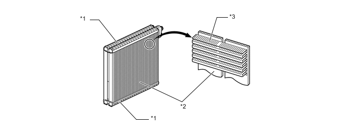
Text in Illustration *1 Tank *2 Micropore Tube *3 Cooling Fin - -
-
-
Evaporator Temperature Sensor (No. 1 Cooler Thermistor)
-
The evaporator temperature sensor (No. 1 cooler thermistor) detects the temperature of the cooled air immediately past the evaporator in the form of resistance changes, and outputs this data to the air conditioning amplifier assembly.
-
-
Blower Motor with Fan Sub-assembly
-
The blower motor with fan sub-assembly has a built-in blower controller, and is controlled with the duty control from the air conditioning amplifier assembly.
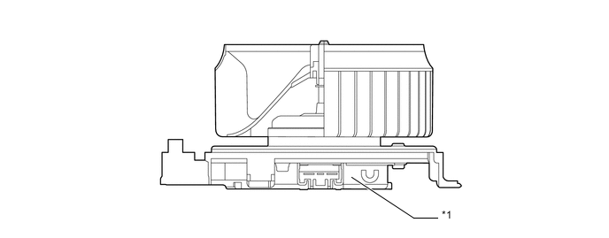
Text in Illustration *1 Built-in Blower Controller - -
-
-
Air Mix Control Film Damper
-
The non-sliding film damper is provided on the air mix control damper. This film damper is independently disposed inside the front air conditioning unit, and thus respective temperature control can be performed. Moreover, the film-like damper is independently fitted on both the warm and cool air sides, thus, the airflow can be independently adjusted on both sides.
-
The airflow volume can be adjusted by increasing the opening of the film. When the opening of the film is made large, the airflow volume is increased, and when the opening of the film is made small, the airflow volume is decreased.
-
In the non-sliding film damper, the spiral shaft fitted in the cassette case of the air mix servo motor is rotated and the winding shaft is moved along the spiral shaft while being vertically rotated, and thus the film damper can be opened and closed and quietness can be enhanced.
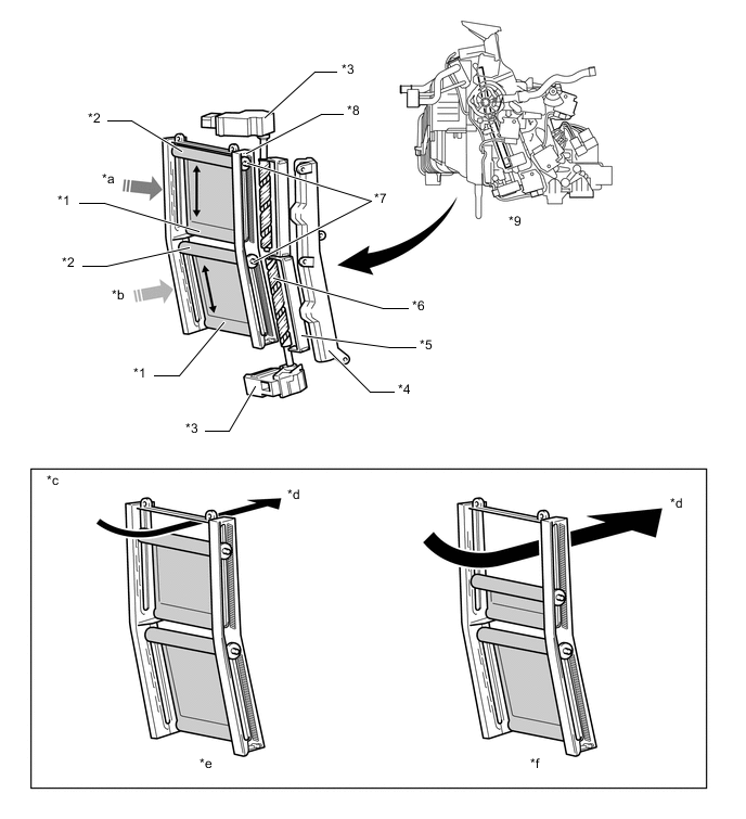
Text in Illustration *1 Film Pressing Member *2 Winding Shaft *3 Servo motor *4 Helical Shaft Cover *5 Helical Shaft Brace *6 Helical Shaft *7 Gear *8 Cassette Case *9 Front Air Conditioning Unit - - *a Cool Air Side *b Warm Air Side *c Image of Airflow Adjustment *d Airflow *e Airflow Volume Down *f Airflow Volume UP
-
-
Bus Connector
-
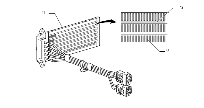
A bus connector is used in the wire harness connection that connects the servomotor from the air conditioning amplifier assembly.
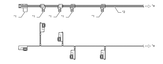
Text in Illustration *1 Bus Connector *2 Air Conditioning Harness Assembly *a To Air Conditioning Amplifier Assembly - - -
The bus connector has a built-in communication/driver IC which communicates with each servomotor connector, actuates the servomotor, and has a position detection function. This enables bus communication for the servomotor wire harness for a more lightweight construction and a reduced number of wires.
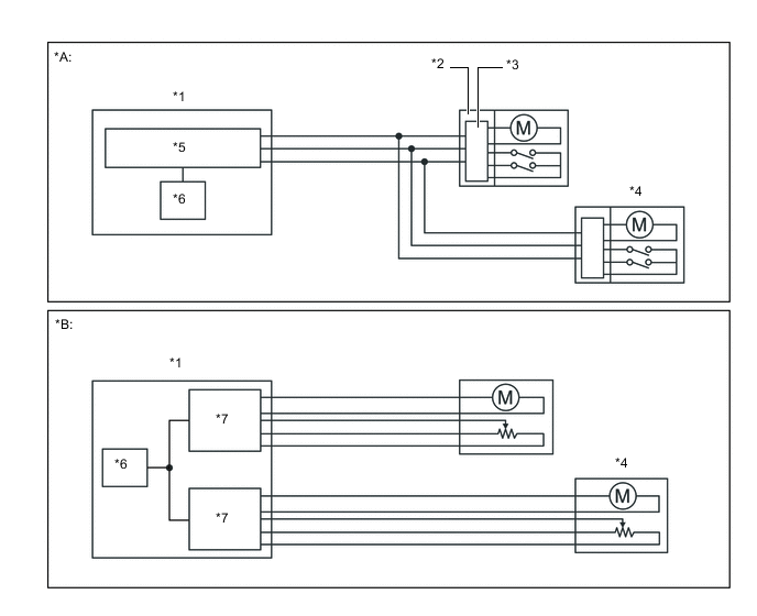
Text in Illustration *A Models with Bus Connector *B Models without Bus Connector *1 Air Conditioning Amplifier Assembly *2 Bus Connector *3 Communication Driver IC *4 Servomotor *5 Communication IC *6 CPU *7 Driver IC - -
-
-
Servo Motor
-
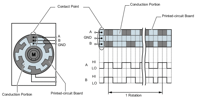
The pulse pattern type servo motor consists of a printed circuit board and a servomotor. The printed circuit board has 3 contact points, and transmits 2 on-off signals to the air conditioning amplifier assembly for the difference of the pulse phase. The smart connector detects the damper position and movement direction with this signal.
-
-
PTC Heater (Quick Heater Assembly) (Models with Quick Heater Assembly)
-
The PTC heater is located above the heater core in the air conditioning unit.
-
The PTC heater consists of a PTC element and an aluminum fin. When current is applied to the PTC element, it generates that to warm the air that passes through the unit.
Text in Illustration *1 PTC Heater (Quick Heater Assembly) *2 PTC Element *3 Aluminum Fin - -
-
-
Clean Air Filter (Air Refiner Element)
-
An air refiner element is used, which can remove odors from the cabin and exhaust gases. Activated charcoal is used for odor reduction, and the life of the air refiner has been prolonged by reducing the amount of desorbing odor which has been already absorbed once.
-
In addition, the fixing material used to adhere activated charcoal to the air refiner element has been optimized and pressure loss reduction has been aimed for in the activated charcoal layer, thus enabling a finer non-woven fabric to achieve removal of micro particles such as pollen.
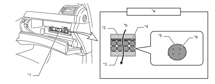
Text in Illustration *1 Air Refiner Element *2 Non-woven Fabric (Upper Flow Side) *3 Non-woven Fabric (Lower Flow Side) *4 Fixing Material (in Sheet Form) *5 Fixing Material (in Particle Form) *6 Activated Charcoal *a Filter Cross Section *b Airflow
-
-
[nanoe] Generator (No. 1 Ion Generator Sub-assembly)
-
The [nanoe] generator (No. 1 ion generator sub-assembly) is provided to enhance the air quality and comfort in the cabin.
-
The [nanoe] outlet of the [nanoe] generator is attached under the heater to register duct. This allows [nanoe] to be released together with air from the driver side center register.
-
The [nanoe] generator is controlled by the air conditioning amplifier assembly and operates when the [nanoe] generator switch is pressed and the blower is on.
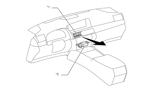
Text in Illustration *1 Center Resistor (Driver Side) *2 [nanoe] Generator (No. 1 Ion Generator Sub-assembly) Note
-
The [nanoe] generator uses a high voltage, which is hazardous. Therefore, if the [nanoe] generator requires repairs, be sure to have them carried out at a Lexus dealer.
-
Do not apply any type of spray (such as a cleaning solvent or hair spray) or stick any foreign matter into the [nanoe] ion outlet, as this could cause improper operation or a malfunction.
-
It is normal for the [nanoe] generator to emit a slight sound during operation. This sound is created when electrons collide with the electrode while [nanoe] are being generated.
-
-
-
Rear Cooling Unit
-
The rear cooling unit assembly is mounted under the package tray trim.
-
The cool box fitted in the innermost part of the armrest can be cooled down by utilizing cool air from the rear cooling unit assembly.
-
Both the front and rear evaporators use the same revolutionary super-slim structure.
-
The blower motor has an built-in blower controller and is controlled with the duty control from the air conditioning amplifier assembly.
-
As in the front air conditioning unit, the servo motor fitted to the rear air conditioning unit is connected to the air conditioning amplifier assembly with the bus connector due to the lightweight construction and a reduced number of wires. Furthermore, the pulse pattern type servo motor is used for the both the front and rear air conditioning unit assemblies.
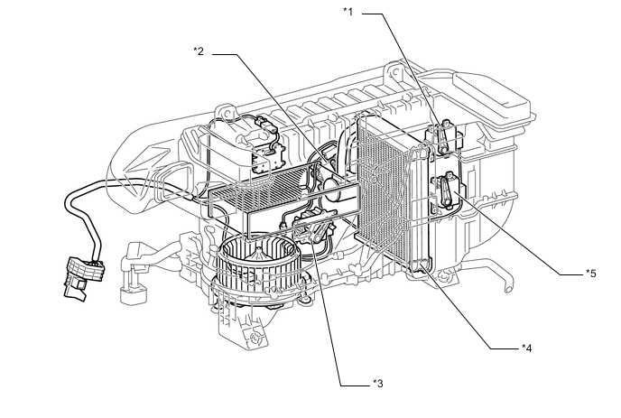
Text in Illustration *1 Rear Air Outlet Servomotor (for RH Side) *2 Rear Exhaust Mode Servomotor *3 Rear Air Mode Damper Servomotor *4 Rear Evaporator Sub-assembly *5 Rear Air Outlet Servomotor (for LH Side) - -
-
-
Rear Air Pulifier (Rear Cooler Filter)
-
This filter is constituted of 2 layers of the electret layer and active charcoal layer. Dust in the cabin can effectively be collected in the electret layer made of high macromolecular fabric to which static electricity is applied.
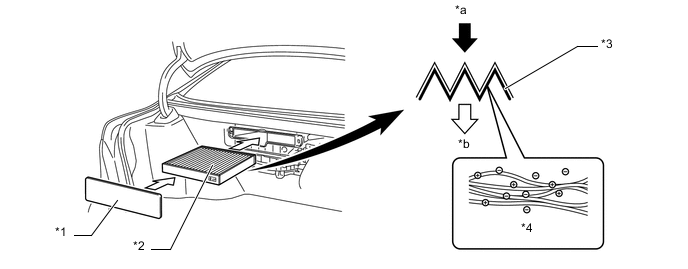
Text in Illustration *1 Filter Cover *2 Rear Cooler Filter *3 Active Charcoal *4 Electret Layer *a Recirculated Air *b Clean Air
-
-
Cooler Condenser Assembly
-
A Multi-Flow (MF) type condenser is used. The condenser consists of 2 cooling portions: a condensing portion and a super-cooling portion, which are integrated together with a gas-liquid separator (modulator). This condenser uses a sub-cool cycle that offers excellent heat-exchange performance.
-
In the sub-cool cycle, after the refrigerant passes through the condensing portion of the condenser, both the liquid refrigerant and the gaseous refrigerant that could not be liquefied are cooled again in the super-cooling portion. Thus, the refrigerant is sent to the evaporator in an almost completely liquefied state.
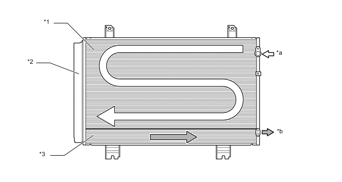
Text in Illustration *1 Condensing Portion *2 Modulator *3 Super-cooling Portion - - *a Gaseous Refrigerant *b Liquid Refrigerant Tech Tips
The point at which the air bubbles disappear in the refrigerant of the sub-cool cycle is lower than the proper amount of refrigerant with which the system must be filled. Therefore, if the system was recharged with refrigerant based on the point at which the air bubbles disappear, the amount of refrigerant would be insufficient. As a result, the cooling performance of the system will be affected. If the system is overcharged with refrigerant, this will also lead to reduced performance.
For the proper method of verifying the amount of refrigerant and for instructions on how to recharge the system with refrigerant, refer to the Repair Manual.
*1 Proper Recharged Amount *2 High Pressure *3 Point in which Bubbles Disappear *4 Amount of Refrigerant
-
-
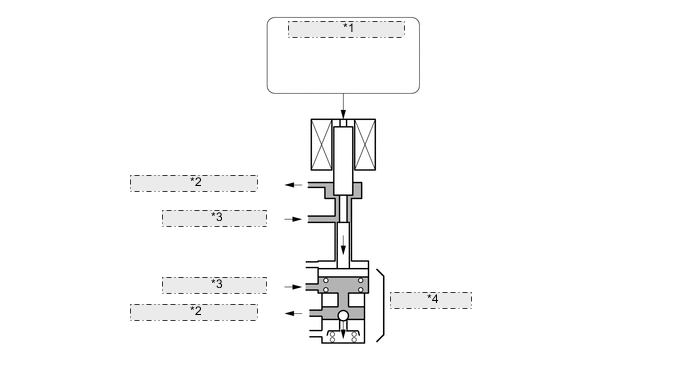
Compressor with Pulley Assembly
-
The compressor with pulley assembly is a continuously variable capacity type in which its capacity can be varied in accordance with the cooling load of the air conditioning.
-
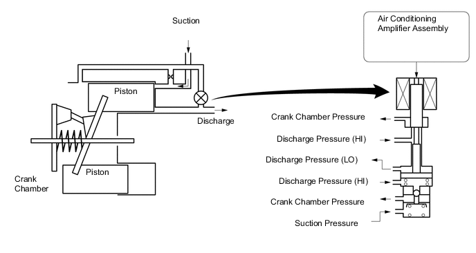
This compressor with pulley assembly consists of the Damper Limiter (DL) type A/C pulley, shaft, lug plate, swash plate, piston, shoe, crank chamber, cylinder, and solenoid valve.
-
A solenoid valve that adjusts the suction pressure so that the compressor with pulley assembly capacity can be controlled as desired is provided.
-
The internal valve is provided to improve the compressor with pulley assembly durability under the high speed and large thermal load conditions. The internal valve is integrated into the solenoid valve.

Text in Illustration *1 Shoe *2 Crank Chamber *3 Lug Plate *4 DL Pulley *5 Shaft *6 Cylinder *7 Solenoid Valve *8 Piston *9 Swash Plate - - -
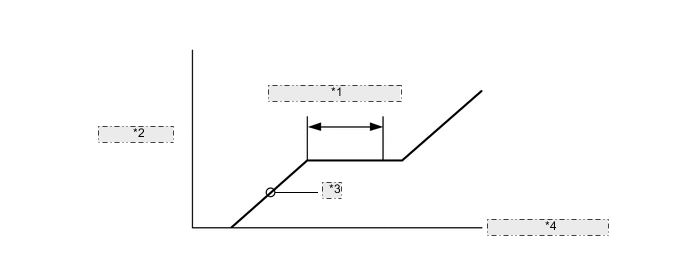
The crank chamber is connected to the suction passage. A solenoid valve is provided between the suction passage (LO pressure) and the discharge passage (HI pressure).
-
The solenoid valve operates under duty cycle control in accordance with the signals from air conditioning amplifier assembly.
-
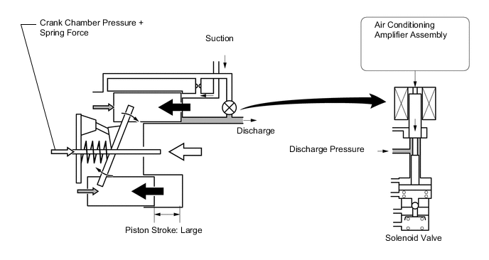
When the solenoid valve closes (solenoid coil is energized), a difference in pressure is created and the pressure in the crank chamber decreases. Then, the pressure that is applied to the right side of the piston becomes greater than the pressure that is applied to the left side of the piston. This compresses the spring and tilts the swash plate. As a result, the piston stroke increases and the discharge capacity increases.
-
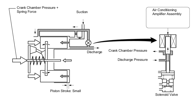
When the solenoid valve opens (solenoid coil is not energized), the difference in pressure disappears. Then, the pressure that is applied to the left side of the piston becomes the same as the pressure that is applied to the right side of the piston. Thus, the spring elongates and eliminates the tilt of the swash plate. As a result, there is no piston stroke and the discharge capacity is reduced.
-
The internal valve operates when compressor with pulley assembly speed has increased rapidly, the compressor with pulley assembly speed is high, or when thermal load has suddenly changed. As a result, the compressor with pulley assembly capacity is reduced, increasing the durability of the compressor with pulley assembly.
*1 Air Conditioning Amplifier Assembly *2 Crank Chamber Pressure *3 Discharge Pressure *4 Internal Valve
-
-
DL Type Pulley
-
This pulley contains a damper to absorb the torque fluctuations of the engine and a limiter mechanism to protect the drive belt in case the compressor locks. In the event that the compressor locks, the limiter mechanism causes the spoke portion of the pulley to break, thus separating the pulley from the compressor with pulley assembly.
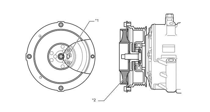
Text in Illustration *1 Spoke Portion *2 Damper
-
-
Air Conditioner Pressure Sensor
-
The air conditioning pressure sensor detects the refrigerant pressure and outputs it to the air conditioning amplifier assembly in the form of voltage changes.
-
-
Cooler (Room Temp. Sensor) Thermistor
-
The cooler (room temp. sensor) thermistor detects the room temperature based on changes in the resistance of its built-in thermistor and sends a signal to the air conditioning amplifier assembly.
-
-
Cooler (Ambient Temp. Sensor) Thermistor
-
The cooler (ambient temp. sensor) thermistor detects the outside temperature based on changes in the resistance of its built-in thermistor and sends a signal to the air conditioning amplifier assembly.
-
-
Cooler (Duct Sensor) Thermistor
-
The cooler (duct sensor) thermistor, fitted to the duct connected to both front right and left registers, detects the air outlet temperature in accordance with the changes in the resistance of the thermistor built into the sensor and sends a signal to the air conditioning amplifier assembly.
-
-
Front Solar Sensor (Automatic Light Control Sensor)
-
The front solar sensor (automatic light control sensor) consists of a photodiode, 2 amplifier circuits for the front solar sensor, and frequency converter circuit for the light control sensor.
-
The front solar sensor (automatic light control sensor) detects (in the form of changes in the current that flows through the built-in photodiode) the changes in the amount of sunlight from the LH and RH sides (2 directions) and outputs these sunlight strength signals to the air conditioning amplifier assembly.
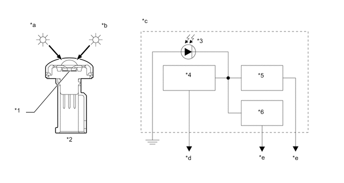
Text in Illustration *1 Sensor Portion *2 Front Solar Sensor (Automatic Light Control Sensor) *3 Photodiode *4 Frequency Convert Circuit *5 Amplifier Circuit (LH) *6 Amplifier Circuit (RH) *a LH Side *b RH Side *c Internal Circuit of Front Solar Sensor *d To Main Body ECU (Driver Side Junction Block) *e To Air Conditioning Amplifier Assembly - -
-
-
Rear Solar Sensor (Cooler (Solar Sensor) Thermistor)
-
The rear solar sensor (cooler (solar sensor) thermistor) contains a photo diode.
-
The rear solar sensor (cooler (solar sensor) thermistor) detects (in the form of changes in the current that floes through the built-in photo diode) the changes in the amount of sunlight from the rear and outputs these sunlight strength signals to the air conditioning amplifier assembly.
-
-
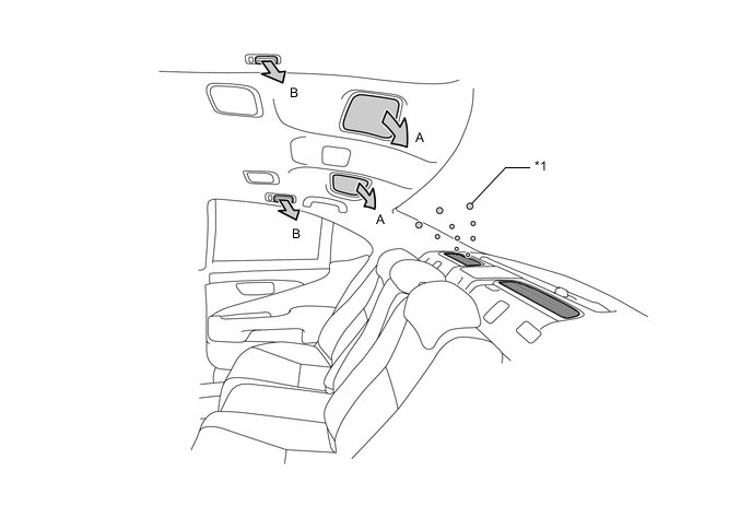
Air Conditioning Infrared Rays Sensor
-
The air conditioning infrared rays sensor for detecting the surface temperature of a rear occupant is used on long body vehicles in order to enhance the comfort of the rear occupants.
-
This sensor, installed in the rear center of the roof, transmits signals to the air conditioning amplifier assembly after detecting the temperatures of rear occupants and rear seats. The air conditioning amplifier assembly calculates the optimal temperature in accordance with the signals and adjusts the temperature so that the rear occupants feel more comfortable.
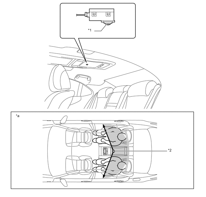
Text in Illustration *1 Sensor Portion *2 Air Conditioning Infrared Rays Sensor *a Sensor Detection Area Overview - -
-
-
Smog Ventilation Sensor
-
The smog ventilation sensor detects harmful elements such as CO, HC and NOx, which are present in the air outside of the vehicle. The sensor outputs the data to the air conditioning amplifier assembly.
-
The sensitivity of the smog ventilation sensor can be adjusted. Adjustment can be performed using the multi-media module receiver assembly and multi display (accessory meter assembly). For details, refer to the Repair Manual.
-
-
-
OPERATION
-
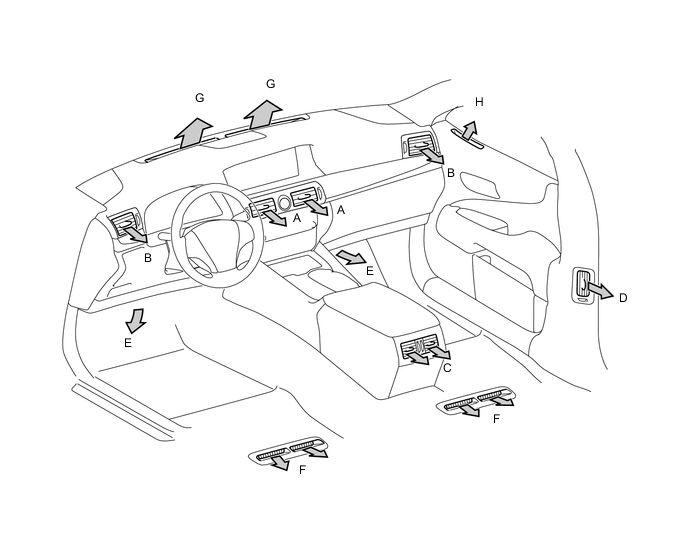
Front Air Conditioning Mode Position and Damper Operation
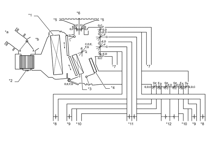
Text in Illustration *1 No. 1 Cooler Evaporator Sub-assembly *2 Blower Motor with Fan Sub-assembly *3 Heater Radiator Unit Sub-assembly *4 PTC Heater (Quick Heater Assembly) *5 Side Defroster *6 Front Defroster *7 Front Footwell Register Duct *8 Side Register *9 Center Pillar Register *10 Rear Footwell Register Duct *11 Front Center Register *12 Rear Center Register *a Fresh Air *b Recirculated Air Mode Position and Damper Operation Control Damper Operation Position Damper Position Operation Air Inlet Control Damper FRESH A Brings in fresh air. RECIRC B Recirculates internal air. Air Mix Control Film Damper MAX COLD to MAX HOT Temperature Setting J, K Varies the ratio of the fresh air and the recirculated air in order to regulate the temperature continuously from HOT to COLD. Cool Air Bypass Damper MAX COLD to MAX HOT Temperature Setting H, I Cool air blows outgo the front center register and side registers in order to adjust the temperature around the heads of the occupants during cooling or warming. Mode Control Door 
DEF C Defrosts the windshield through the center defroster, side defroster and side register. 
FOOT/DEF D Defrosts the windshield through the center defroster, side defroster, side register and rear center register, while air is also blown out from the front and rear footwell register ducts. 
FOOT E Blows air out of the footwell register duct, and side register. In addition, air blows out slightly from the center defroster and side defroster. 
BI-LEVEL F Blows air out of the front and rear center registers, side register, center pillar register and front and rear footwell register ducts. 
FACE G Blows air out of the front and rear center registers, center pillar register and side register. -
Rear Air Conditioning Mode Position and Damper Operation
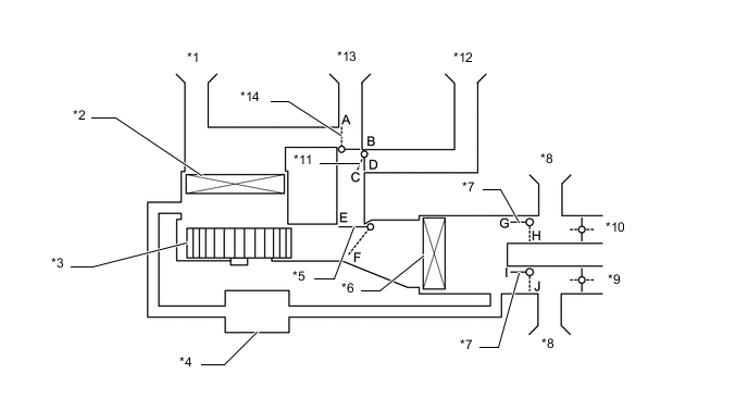
Text in Illustration *1 Air Inlet Register Duct *2 Rear Cooler Filter *3 Rear Blower Motor with Fan Assembly *4 Cool Box *5 Mode Control Damper *6 Rear Evaporator Sub-assembly *7 Air Outlet Control Damper *8 Roof Register *9 Roof Side Register (RH) *10 Roof Side Register (LH) *11 Exhaust Control Damper *12 Exhaust Register Duct *13 Air Inlet/Dispersal Register Duct *14 Air Inlet Control Damper Function of Main Damper Control Damper Operation Position Damper Position Operation Air Inlet/Outlet Control Damper and Exhaust Control Damper Air Purifier On (Fresh Mode) A, C, F, H, J Cleaned air is discharged from the air vent in the luggage compartment. Air Purifier On (Recirculated Mode) A, D, F, H, J Cleaned air blows out of the dispersal register duct. Rear Air Conditioning On B, E, G, I Air blows out of the roof side register. -
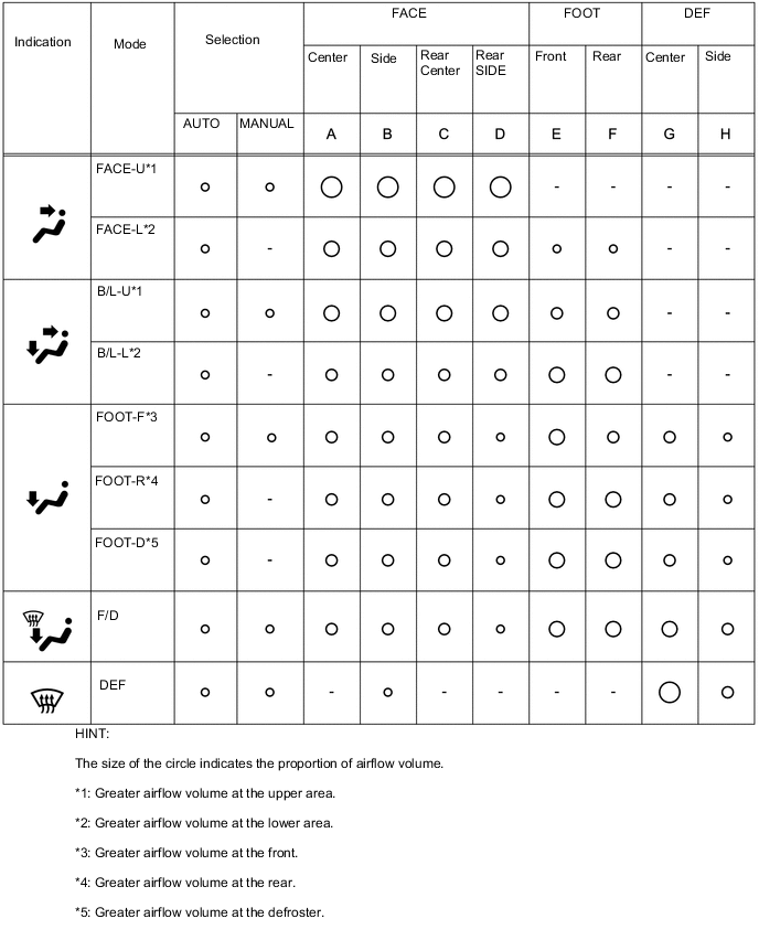
Air Outlets and Airflow Volume (Front Air Conditioning)
-
Air Outlets and Airflow Volume (Rear Air Conditioning)
Text in Illustration *1 Clean Air (Air Purifier On) - - Air Outlet Mode Selectable Mode Register Automatic Manual Roof (A) Roof Side (B) FACE 

Tech Tips
The size of the circle ○ indicates the proportion of airflow volume.
-
[nanoe] Generator Operation
-
The [nanoe] generator (No. 1 ion generator sub-assembly) gathers moisture in the air, generates [nanoe] by applying a high level of electric voltage and emits it from the driver side center register to the cabin.
-
Electrodes and a Peltier device are installed in the [nanoe] generator. The electrodes cooled by applying current to the Peltier device generate [nanoe] by applying a high level of electric voltage to water drops created by dew condensation.
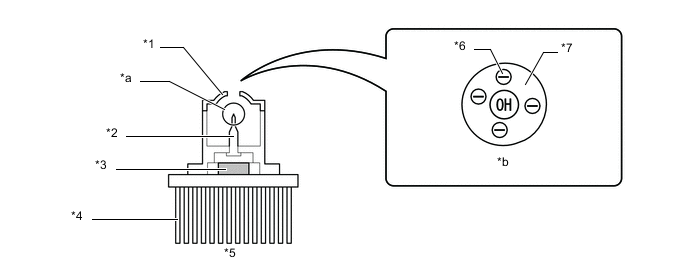
Text in Illustration *1 Counter Electrode *2 Electrode *3 Peltier Device *4 Heatsink *5 [nanoe] Generator (No. 1 Ion Generator Sub-assembly) *6 Electron *7 Water - - *a [nanoe] Generation Portion *b Image of [nanoe]
-
-