MONITOR SYSTEM DETAILS
-
FUNCTION OF MAIN COMPONENTS
Component Function Rear Television Camera Assembly Transmits a video signal of the area behind the vehicle to the radio and display receiver assembly*1 or navigation receiver assembly*2. Radio and Display Receiver Assembly*1
-
Receives signals from the park/neutral position switch assembly and turns the rear television camera assembly on and off.
-
Displays the image transmitted by the rear television camera assembly on the screen.
Navigation Receiver Assembly*2 Park/Neutral Position Switch Assembly Sends an R shift position signal to the radio and display receiver assembly*1 or navigation receiver assembly*2.
-
*1: Models with Entune audio system or Entune audio plus system
-
*2: Models with Entune premium audio with navigation and App Suite system or Entune premium JBL audio with navigation and App Suite system
-
-
OPERATING CONDITION
-
This system operates when both the following conditions have been met:
-
Ignition switch is ON.
-
Shift lever is in R.
-
-
-
FUNCTION
-
Area Displayed on Screen
-
Objects on the right of the vehicle appear on the right side of the display panel, and objects on the left of the vehicle appear on the left side of the display panel.
-
The rear television camera uses a wide-angle lens. The perceived distance from images that appear on the screen differs from the actual distance.
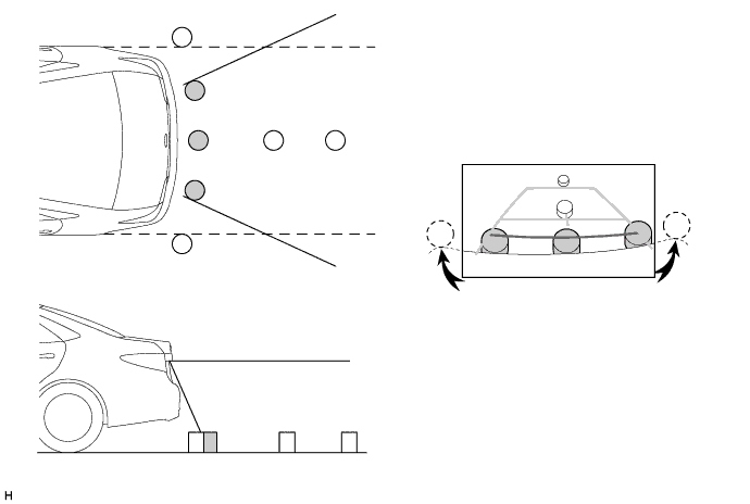
Note
The area displayed on the screen may vary according to vehicle status or road conditions. The area covered by the rear television camera assembly is limited. The rear television camera assembly does not show objects close to either corner of the bumper or show the area under the bumper.
-
-
-
CONSTRUCTION
-
Rear Television Camera Assembly
-
The rear television camera assembly consists of a wide-angle lens and a Complementary Metal Oxide Semiconductor (CMOS).
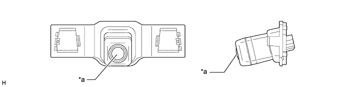
Text in Illustration *a Wide-angle Lens - -
-
-
Multi-display (Rear View Monitor Display)
-
When reverse is selected, the display shows the image from the rear television camera assembly.
-
When the multi-display shows the image of the area behind the vehicle, the parking guide lines are also displayed.
-
A description of the parking guide line mode display is provided in the following diagram.
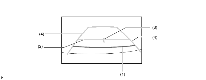
Item Description (1) Distance Guide Line (Red) Indicates a position on the ground about 0.5 m (1.5 ft.) behind the rear bumper. (2) Distance Guide Line (Blue) Indicates a position on the ground about 1.0 m (3.0 ft.) behind the rear bumper. (3) Vehicle Center Guide Line (Blue) Indicates the estimated position on the ground of the center of the vehicle. (4) Vehicle Width Guide Lines (Blue) Indicate the estimated vehicle width.
-
-
-
FAIL-SAFE
-
The table below indicates fail-safe operation when a malfunction is detected:
Malfunctioning Part Detection Item Function Rear Television Camera Assembly Rear television camera assembly malfunction signal is detected. System stops signal reception and displays a dark screen.
-