SFI SYSTEM PARTS LOCATION
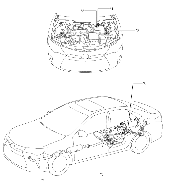
| *1 | Purge VSV | *2 | Intake Mass Air Flow Meter Sub-assembly - Intake Air Temperature Sensor |
| *3 | ECM | *4 | Oxygen Sensor |
| *5 | Fuel Suction Tube with Pump and Gauge Assembly | *6 | Canister Pump Module - Vent Valve - Leak Detection Pump - Canister Pressure Sensor |
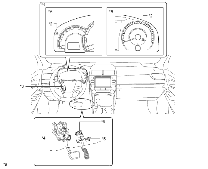
| *A | Models without Multi-information Display | *B | Models with Multi-information Display |
| *1 | Combination Meter Assembly | *2 | Malfunction Indicator Lamp (MIL) |
| *3 | Main Body ECU (Multiplex Network Body ECU) | *4 | Stop Light Switch Assembly |
| *5 | DLC3 | *6 | Accelerator Pedal Sensor Assembly - Accelerator Pedal Position Sensor |
| *a | This illustrations shown are examples only. | - | - |
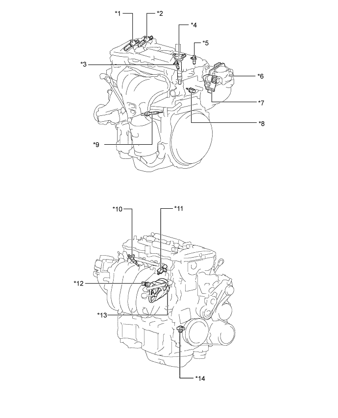
| *1 | Camshaft Timing Oil Control Valve Assembly (Exhaust Side) | *2 | Camshaft Timing Oil Control Valve Assembly (Intake Side) |
| *3 | Camshaft Position Sensor (Exhaust Side) | *4 | Ignition Coil Assembly |
| *5 | Camshaft Position Sensor (Intake Side) | *6 | Throttle Body with Motor Assembly - Throttle Position Sensor - Throttle Control Motor |
| *7 | Intake Air Control Valve Actuator | *8 | E. F. I. Engine Coolant Temperature Sensor |
| *9 | Air Fuel Ratio Sensor | *10 | Fuel Injector Assembly |
| *11 | Vacuum Switching Valve Assembly (For ACIS) | *12 | Knock Control Sensor |
| *13 | ACIS Valve Actuator | *14 | Crank Position Sensor |