NEW FEATURES
-
DESCRIPTION
-
The air injection control has been adopted.*
Tech Tips
*: Models with EURO 4
-
-
FEATURES OF 3UR-FE ENGINE
-
The 3UR-FE engine has achieved the following performance through the use of the items listed below.
-
(1) High performance and reliability
-
(2) Low noise and vibration
-
(3) Lightweight and compact design
-
(4) Good serviceability
-
(5) Clean emissions and fuel economy
Item (1) (2) (3) (4) (5) Engine Proper A taper squish shape is used for the combustion chamber. ○ - - - ○ An aluminum alloy cylinder block sub-assembly containing a water distribution pathway is used. ○ - ○ - - Spiny-type liners are used in the cylinder bores. ○ - ○ - - Water jacket spacers are used. ○ - - - - The piston skirt is coated with resin. ○ ○ - - ○ An oil pan sub-assembly made of aluminum alloy is used. ○ ○ ○ - - Valve Mechanism Timing chains and chain tensioners are used. ○ - ○ - - Valve lash adjuster assemblies are used. ○ ○ - ○ ○ Valve rocker arm sub-assemblies are used. ○ - - - ○ Lubrication System An oil filter with a replaceable element is used. - - - ○ - A water-cooled type oil cooler assembly is used. ○ - - - - Cooling System TOYOTA Genuine Super Long Life Coolant (SLLC) is used. - - - ○ - Intake and Exhaust System A link-less type throttle body is used. ○ - ○ - - An intake manifold made of plastic is used. ○ - ○ - - Stainless steel exhaust manifolds are used. ○ - ○ - ○ Ceramic type Three-Way Catalytic converters (TWCs) are used. - - - - ○ Fuel System 12-hole type fuel injector assemblies are used to improve the atomization of fuel. ○ - - - ○ Ignition System The Direct Ignition System (DIS) makes ignition timing adjustment unnecessary. ○ - - ○ ○ Long-reach type iridium-tipped spark plugs are used. ○ - ○ ○ Charging System A segment conductor type generator assembly is used. ○ - ○ - - Starting System A planetary reduction type starter assembly is used. - - ○ - - Serpentine Belt Drive System A serpentine belt drive system is used. - - ○ ○ - Blowby Gas Ventilation System A separator case is provided between the cylinder block sub-assembly and the intake manifold. ○ - - - ○ Engine Control System Magnetic Resistance Element (MRE) type crank position, cam position, and VVT sensors are used. ○ - - - - The Electronic Throttle Control System-intelligent (ETCS-i) is used. ○ - - - ○ The dual Variable Valve Timing-intelligent (VVT-i) system is used. ○ - - - ○ The Acoustic Control Induction System (ACIS) is used. ○ - - - ○ An air injection system is used.*
- - - - ○ The starter control (cranking hold function) is used. ○ - - - - An evaporative emission control system is used. - - - - ○ Tech Tips
*: Models with EURO 4
-
-
-
ENGINE PROPER
-
Cylinder Head
-
An air injection port is provided for the air injection control.
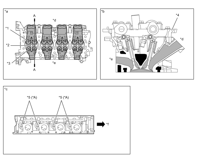
*A Models with Air Injection Control - - *1 Intake Valve *2 Spark Plug Hole *3 Exhaust Valve *4 Camshaft Housing *5 Air Injection Port - - *a Bottom Side View *b A - A Cross Section *c Exhaust Side View *d Intake Side *e Exhaust Side *f Front
-
-
-
INTAKE AND EXHAUST SYSTEM
-
Exhaust Manifold
-
Air injection pipes are provided for the exhaust manifold sub-assembly RH and LH.*
Tech Tips
*: Models with air injection control
Figure 1. Models with Air Injection Control
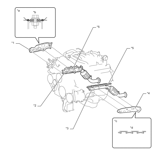
*1 No. 1 Exhaust Manifold Heat Insulator *2 Exhaust Manifold Sub-assembly RH *3 Exhaust Manifold Sub-assembly LH *4 No. 2 Exhaust Manifold Heat Insulator *5 Air Injection Pipe - - *a Heat Insulator Tightened Area Cross Section *b Floating Construction *c Heat Insulator Cross Section *d Corrugated
-
-
-
ENGINE CONTROL SYSTEM
-
General
-
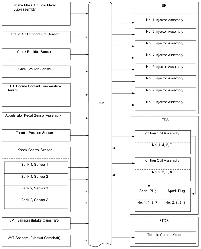
The engine control system of the 3UR-FE engine has the following features.
System Outline Sequential Multiport Fuel Injection (SFI)
-
An L-type EFI system directly detects the intake air mass using a hot wire type intake mass air flow meter sub-assembly.
-
An independent injection system (in which fuel is injected once into each intake port for each 2 revolutions of the crankshaft) is used.
-
Fuel injection takes 2 forms:
-
Synchronous injection, in which injection always occurs at the same timing relative to the firing order.
-
Non-synchronous injection in which injection is effected regardless of the crankshaft angle.
-
Synchronous injection is further divided into group injection during a cold start, and independent injection after the engine is started.
Electronic Spark Advance (ESA)
-
Ignition timing is determined by the ECM based on signals from various sensors. The ECM corrects ignition timing in response to engine knocking.
-
This system selects the optimal ignition timing in accordance with the signals received from the sensors and sends the (IGT) ignition signal to the igniter.
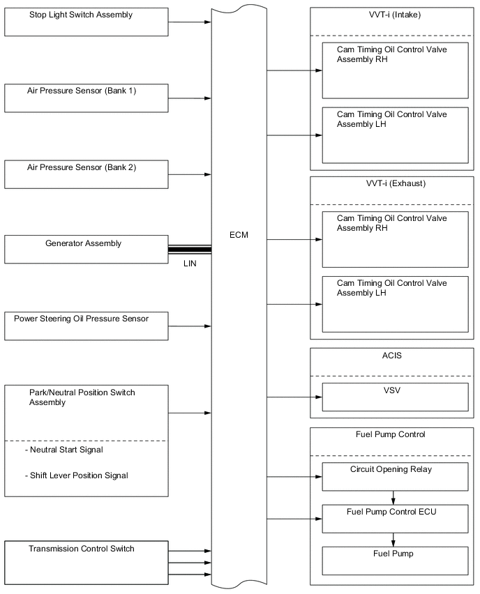
Electronic Throttle Control System-intelligent (ETCS-i) Optimally controls the throttle valve opening in accordance with the amount of accelerator pedal effort and the condition of the engine and the vehicle. Dual Variable Valve Timing-intelligent (VVT-i) Controls the intake and exhaust camshafts to optimal valve timing in accordance with the engine operating conditions. Acoustic Control Induction System (ACIS) The intake air passages are switched based on engine speed and throttle valve opening angle to provide high performance in all engine speed ranges. Fuel Pump Control
-
Based on signals from the ECM, the fuel pump ECU controls the fuel pump speed.
-
The fuel pump is stopped when the SRS airbag is deployed in a frontal, side, or side rear collision.
Air Injection Control*
The ECM controls the air injection time based on the signals from the crank position sensor, engine coolant temperature sensor, intake mass air flow meter sub-assembly and air pressure sensor. Starter Control (Cranking Hold Function) Once the engine switch is pushed, while the brake pedal is depressed, this control continues to operate the starter until the engine started. Air Fuel Ratio Sensor and Oxygen Sensor Heater Control Maintains the temperature of the air fuel ratio sensors or oxygen sensors at an appropriate level to increase the detection accuracy of the exhaust gas oxygen concentration. Air Conditioning Cut-off Control By turning the air conditioning compressor on or off in accordance with the engine condition, drivability is maintained. Evaporative Emission Control The ECM controls the purge flow of evaporative emission (HC) in the charcoal canister assembly in accordance with the engine conditions. Engine Immobiliser Prohibits fuel delivery and ignition if an attempt is made to start the engine with an invalid key. Brake Override System The driving torque is restricted when both the accelerator and brake pedals are depressed. (For the Activation Conditions and Inspection Method, refer to the repair manual.) Diagnosis When the ECM detects a malfunction, it records the malfunction and memorizes information related to the fault. Fail-safe When the ECM detects a malfunction, it stops or controls the engine according to the data already stored in the memory. Tech Tips
*: Models with EURO 4
-
-
-
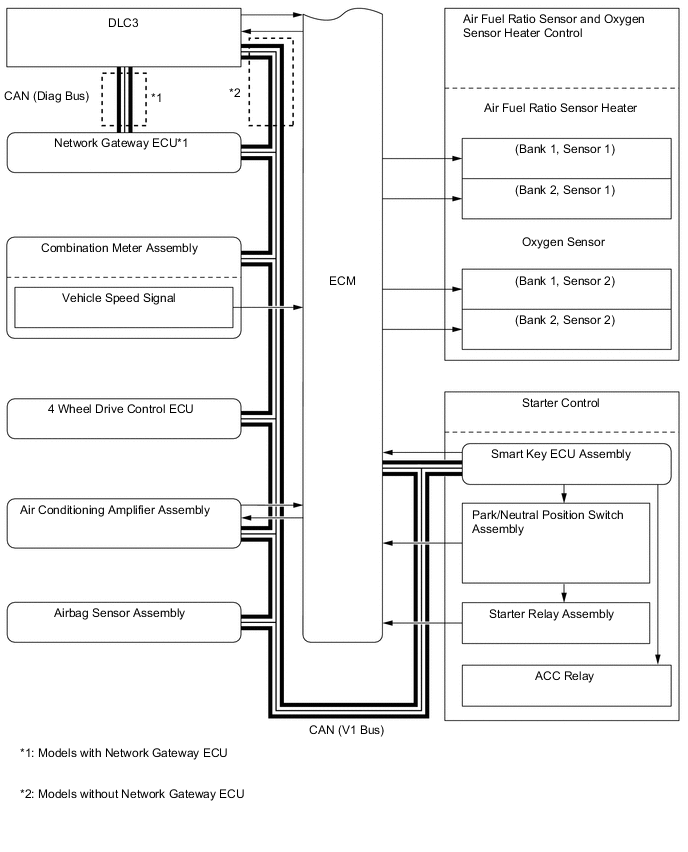
Construction
-
The configuration of the engine control system is as shown in the following chart.
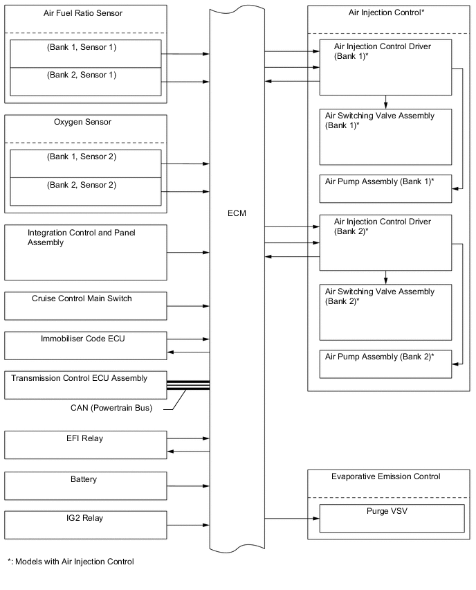
-
-
Layout of Main Components
Figure 2. Models with Air Injection Control
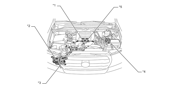
*1 Air Switching Valve Assembly (Bank 2)
-
Air Pressure Sensor
*2 Air Pump Assembly (Bank 2) *3 Air Pump Assembly (Bank 1) *4 Air Injection Control Driver *5 Air Switching Valve Assembly (Bank 1)
-
Air Pressure Sensor
- - -
-
Air Injection System (Models with Air Injection Control)
-
General
-
To ensure the proper warm-up performance of the Three-Way Catalytic converters (TWCs) after starting a cold engine, an air injection system is used.
-
For this system, each of the bank 2 (right bank) and bank 1 (left bank) has an air pump assembly, air injection control driver, air switching valve assembly, and air pressure sensor. Control of the right bank and left bank is performed independently. 2 pumps are used to increase the amount of air supplied, shortening the catalyst warm-up time.
-
The ECM estimates the amount of air injected to the TWCs based on signals from the intake mass air flow meter sub-assembly in order to regulate the air injection time.
-
Air is injected under the following conditions.
Operation Conditions Engine Coolant Temperature 5°C to 45°C (41°F to 113°F) Intake Air Temperature 5°C (41°F) or more Figure 3. System Diagram
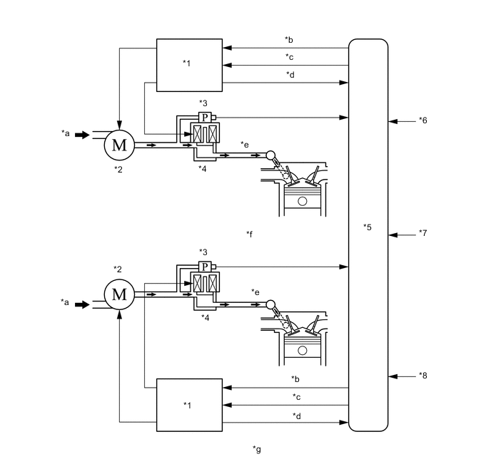
*1 Air Injection Control Driver *2 Air Pump Assembly *3 Air Pressure Sensor *4 Air Switching Valve Assembly *5 ECM *6 Engine Coolant Temperature Sensor *7 Intake Mass Air Flow Meter Sub-assembly *8 Intake Air Temperature Sensor *a Air *b Pump Actuation Request *c Valve Actuation Request *d Diagnosis Signal *e to Exhaust Manifold Sub-assembly *f Bank 2 (Right Bank) *g Bank 1 (Left Bank) - -
-
-
Construction and Operation
-
Air Pump
-
Each air pump assembly consists of a DC motor, an impeller and an air filter.
-
The air pump assembly supplies air into an air injection control valve using its impeller.
-
The air filter is maintenance-free.
-
The structure and function of the air pump assemblies for the bank 1 and bank 2 are basically the same.
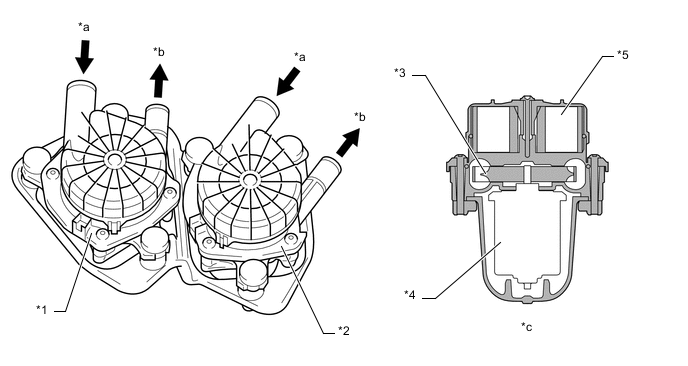
*1 Air Pump Assembly (Bank 2) *2 Air Pump Assembly (Bank 1) *3 Impeller *4 DC Motor *5 Air Filter - - *a Air In *b Air Out *c Cross Section - - -
Air Switching Valve
-
The air switching valve assembly is operated by a solenoid coil to control air injection and prevent back-flow of exhaust gas. Opening timing of the valve is synchronized with the operation timing of the air pump assembly.
-
An air pressure sensor is built into the corresponding air switching valve assembly.
-
The structure and function of the air switching valve assemblies for the bank 1 and bank 2 are basically the same.
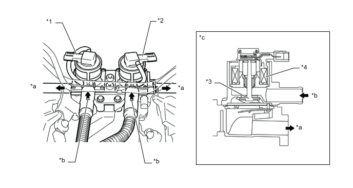
*1 Air Switching Valve Assembly (Bank 2) *2 Air Switching Valve Assembly (Bank 1) *3 Valve *4 Solenoid Coil *a Air Out *b Air In *c Cross Section (for Bank 1) - - -
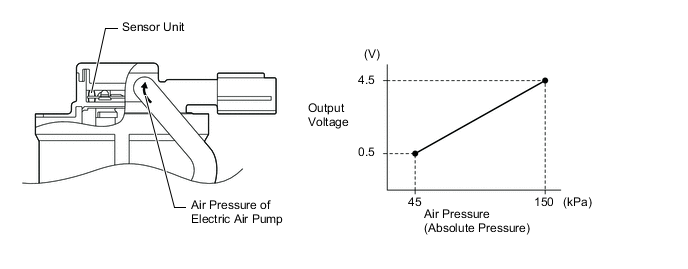
Air Pressure Sensor
-
The air pressure sensor consists of a semiconductor, which has a silicon chip that changes its electrical resistance when pressure is applied to it. The sensor converts the pressure into an electrical signal, and sends it to the ECM in an amplified form.
-
The structure and function of the air pressure sensors for the bank 1 and bank 2 are basically the same.
-
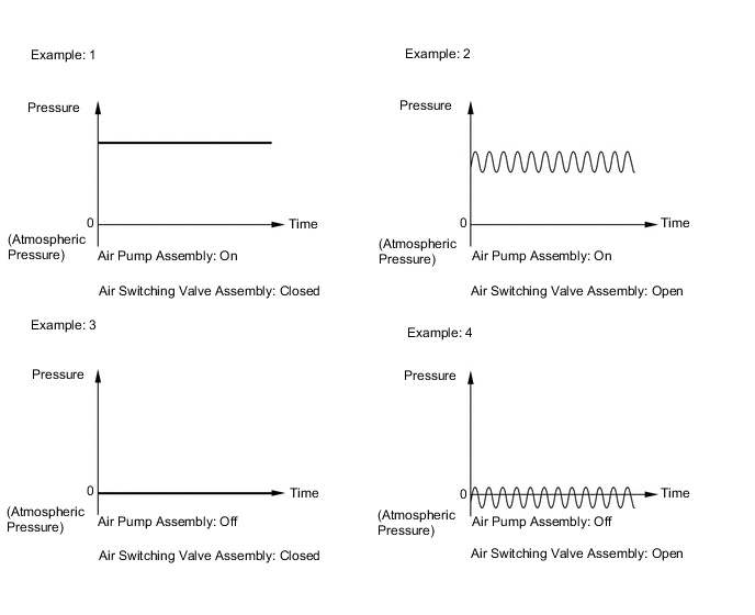
The ECM detects operation of the air injection system based on signals from the air pressure sensor as follows:
-
When the air pump assembly is on and the air switching valve assembly is closed, the pressure is stable.
-
When the air pump assembly is on and the air switching valve assembly is open, the pressure drops slightly and becomes unstable because of exhaust pulses.
-
When the air pump assembly is off and the air switching valve assembly is closed, the pressure remains at atmospheric pressure.
-
When the air pump assembly is off and air switching valve assembly is open, the pressure drops below atmospheric pressure and becomes unstable because of exhaust pulses.
-
Air Injection Control Driver
-
A semiconductor type air injection control driver is used. Activated by the ECM, this driver actuates the air pump assembly and the air switching valve assembly.
-
The air injection control driver also detects failures in the input and output circuits of the air injection driver and transmits the failure status to the ECM via duty cycle signals.
-
The basic functions of the air injection control drivers for the bank 1 and bank 2 are the same. The following system chart shows the bank 1 (left bank).
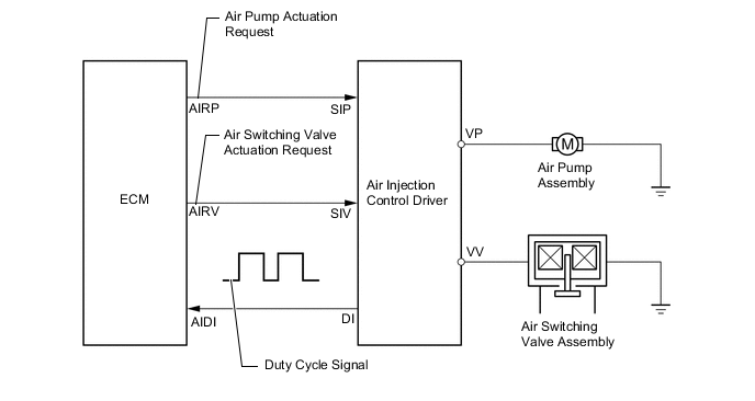
DI Terminal Output Condition AIRP AIRV Output (Duty Cycle Signal) Open circuit in line between AIDI and DI terminals. - - 
Failure in line between ECM terminals and air injection control driver. - - 
Output failure at air injection control driver. (Failure in air pump actuation circuit) - - 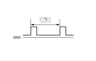
*1 200 ms Output failure at air injection control driver. (Failure in air switching valve actuation circuit) - - 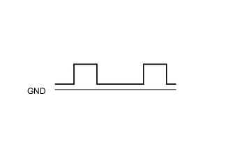
Overheat failure of air injection control driver. - - 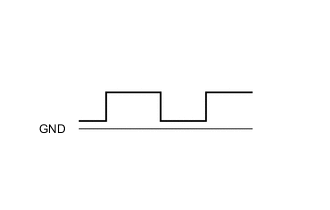
Normal On On 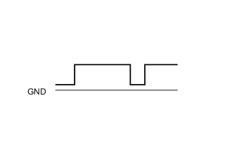
Off Off On Off Off On
-
-
-