NEW FEATURES
-
GENERAL
-
Outline
-
ERA-GLONASS is a telematics service*that uses Global Navigation Satellite System (GNSS) and cellular service (telephone function).
-
ERA-GLONASS is a service that provides emergency assistance when the vehicle is involved in an accident or is malfunctioning. After receiving an emergency call from the vehicle, depending on the situation, a Public Safety Answering Point (PSAP) operator contacts the police and/or an ambulance.
-
ERA-GLONASS provides 2 types of services: Automatic Emergency Call Service and Manual Emergency Call Service.
-
ERA-GLONASS consists mainly of the telematics transceiver (data communication module), mobilephone battery (back-up battery), telephone antenna assembly (telephone and GNSS antenna), manual (SOS) switch, telephone microphone assembly and manual (SOS) switch indicators.
Tech Tips
*: ERA-GLONASS is available in Russia and Kazakhstan.
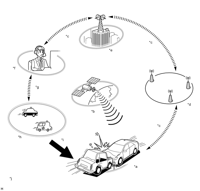
*a Emergency Call Service *b GNSS Satellite *c Cellular Phone Line *d Cellular Phone Base Station *e Mobile Network Operator (MNO) or Mobile Virtual Network Operator (MVNO) *f Public Safety Answering Point (PSAP) *g Public Fixed Line *h Emergency Vehicle *i Public safety authorities such as police or fire department *j The illustrations shown are examples only. The llustrations may differ from the actual service.
-
-
Precaution
-
Mobilephone Battery (Back-up Battery)
-
The mobilephone battery (back-up battery) has a service life of not less than 3 years. When the mobilephone battery (back-up battery) needs to be replaced, the manual (SOS) switch red indicator will come on. The telematics transceiver (data communication module) will also store a Diagnostic Trouble Code (DTC).
-
-
-
-
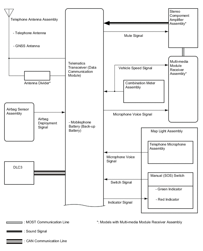
SYSTEM DIAGRAM
-
PARTS LOCATION
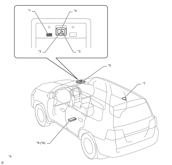
*A Models with Multi-media Module Receiver Assembly - - *1 Telephone Microphone Assembly *2 Manual (SOS) Switch Green Indicator *3 Manual (SOS) Switch Red Indicator *4 Manual (SOS) Switch *5 Map Light Assembly *6 Stereo Compornent Amplifier Assembly *7 Telephone Antenna Assembly
-
Telephone Antenna
-
GNSS Antenna
- - *a The illustrations shown are examples only. - - 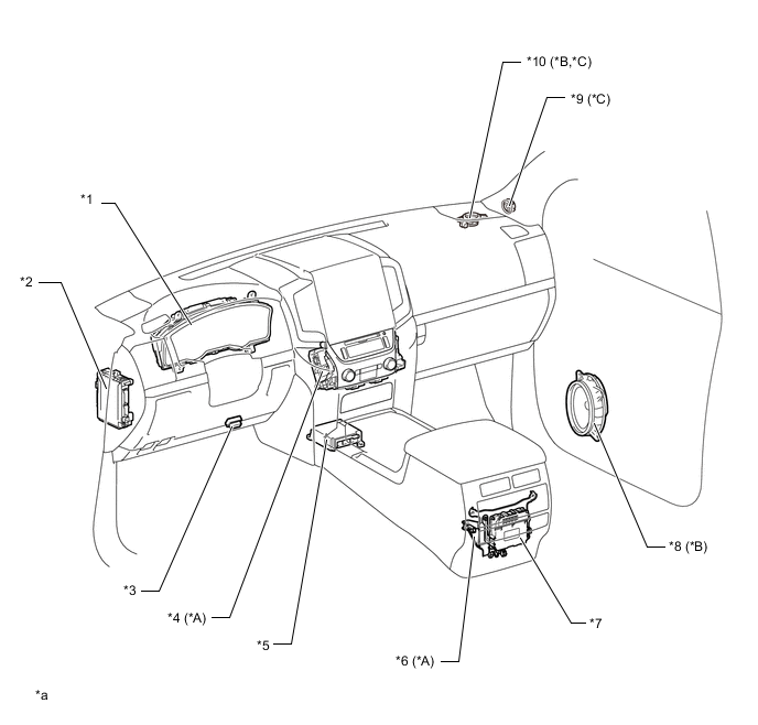
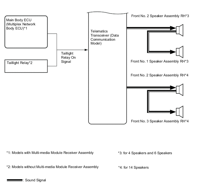
*A Models with Multi-media Module Receiver Assembly *B for 4 Speakers and 6 Speakers *C for 14 Speakers - - *1 Combination Meter Assembly *2 Main Body ECU (Multiplex Network Body ECU) *3 DLC3 *4 Multi-media Module Receiver Assembly *5 Airbag Sensor Assembly *6 Antenna Divider *7 Telematics Transceiver (Data Communication Model)
-
Mobilephone Battery (Back-up Battery)
*8 Front No. 1 Speaker Assembly RH *9 Front No. 3 Speaker Assembly RH *10 Front No. 2 Speaker Assembly RH *a The illustrations shown are examples only. - - -
-
FUNCTION OF MAIN COMPONENTS
-
The main components in the ERA-GLONASS system have the following functions:
Component Function Map Light Assembly Telephone Microphone Assembly Receives the user's voice through the microphone module. Manual (SOS) Switch When pressed, allows the driver to connect to and communicate with the PSAP as an emergency assistance button (SOS) service. Manual (SOS) Switch Indicator Green
-
Turns on when the system is operating normally with in the service area.*1
-
Blinks during a call and turns off when the system is malfunctioning.
Red
-
Illuminates to warn the user when a malfunction occurs in the system.
-
Turns off when the system is operating normally.
Telematics Transceiver
(Data Communication Module)
-
Connects to the PSAP and allows the driver to speak with the call center operator when the automatic emergency call service or the manual emergency call service is active.
-
The cellular phone module makes or receives calls.
-
The telematics transceiver (data communication module) receives signals from the GNSS antenna, calculates the position of the vehicle and transmits it to the PSAP.
-
Controls the on/off and blinking actions of the manual (SOS) switch indicators.
-
Dims the manual (SOS) switch indicator when the taillight relay on signal is received.
-
Sends the PSAP operator's voice and voice prompts to the front speakers.
Mobilephone Battery
(Back-up Battery)
Is built into the telematics transceiver (data communication module) and supplies power to the telematics transceiver (data communication module) when the automatic emergency call service is activated and the vehicle battery cannot supply power. Telephone Antenna Assembly Telephone Antenna Is for a cellular phone antenna which is compatible with the transmission and reception of frequency bands of cellular phones. It transmits signals from the telematics transceiver (data communication module) and receives signals from the call center. GNSS Antenna Receives the signals from GNSS satellites and transmits these signals to the antenna divider*2or telematics transceiver (data communication module)*3.
Antenna Divider*2
Receives the signals from GNSS antenna and transmits signals to the telematics transceiver (data communication module). Airbag Sensor Assembly Sends an activation signal to the telematics transceiver (data communication module) when the airbags deploy. (An automatic emergency call service is made.) Front Speakers Outputs the PSAP operator's voice. Multi-media Module Receiver Assembly*2
Receives microphone voice signals from the telematics transceiver (data communication module). Stereo Component Amplifier Assembly*2
Inputs the mute signal from the telematics transceiver (data communication module) to mute any audio sound. Combination Meter Assembly Sends the vehicle speed signal to the telematics transceiver (data communication module) and multi-media module receiver assembly*2.
Main Body ECU (Multiplex Network Body ECU)*2, Taillight Relay*3
Sends the taillight relay on signal to the telematics transceiver (data communication module). DLC3 Allows system diagnosis to be performed when Global TechStream (GTS). Tech Tips
*1: ERA-GLONASS is available in Russia and Kazakhstan.
*2: Models with multi-media module receiver assembly
*3: Models without multi-media module receiver assembly
-
-
-
FUNCTION
-
Automatic Emergency Call Service
-
If any of the airbags are deployed due to a serious collision, the telematics transceiver (data communication module) receives the deployment signal from the airbag sensor assembly. After receiving the deployment signal, the telematics transceiver (data communication module) automatically makes an emergency call and transmits the vehicle location and user information to the PSAP closest to the vehicle.
-
The system is then automatically connected to a PSAP and the user can talk to a PSAP operator. The PSAP operator contacts the emergency services when the user is unable to answer.
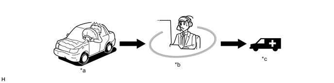
*a Airbag Deployment or Collision Detection *b Public Safety Answering Point (PSAP) *c Ambulance - -
-
-
Manual Emergency Call Service
-
By pushing the manual (SOS) switch during an on-road emergency, the telematics transceiver (data communication module) transmits the vehicle location and user information, and calls to the PSAP closest to the vehicle.
-
The PSAP operator determines the level of the emergency based on the vehicle location and from the conversation with the user, and contacts the emergency services if necessary.

*1 Manual (SOS) Switch - - *a Public Safety Answering Point (PSAP) - -
-
-
-
DIAGNOSIS
-
If there is a malfunction in the system, the telematics transceiver (data communication module) stores Diagnostic Trouble Codes (DTCs) in its memory. For details, refer to the Repair Manual.
-
-
MANUAL (SOS) SWITCH INDICATOR
-
Construction
-
When the engine switch is turned on, the manual (SOS) switch red indicator illuminates for 10 seconds and then turns off. Then, the manual (SOS) switch green indicator will illuminate for 2 seconds. Illuminates, blinks or turns off depending on the mode type.
-
When the engine switch is turned off, the manual (SOS) switch red indicator and manual (SOS) switch green indicator turn off. However, if the engine switch is turned off when an automatic emergency call is in progress, the call continues and the indicator lights continue operating.
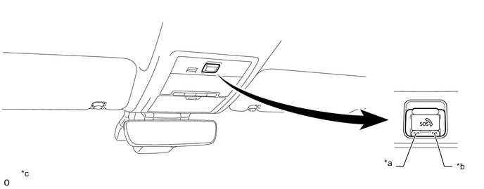
*a Manual (SOS) Switch Green Indicator *b Manual (SOS) Switch Red Indicator *c The illustrations shown are examples only. - - -
Indicators shown in each mode are as follows:
Manual (SOS) Switch Indicator Operation Condition Green Red ON OFF The system is operating (the vehicle is within the cellular phone service area). OFF ON
-
A related device is malfunctioning.
-
The mobilephone battery (back-up battery) needs to be replaced.
Blinks OFF An emergency call is being performed. OFF Blinks An emergency call has failed. OFF OFF The engine switch is off. -
-
-