NEW FEATURES
-
DESCRIPTION
-
Conditions on VSC and TRC have been added to the conditions for Manual Cancel Control.*
-
Part of the circuit has been altered along with the new Controller Area Network (CAN) communication system.
*: Models with VSC system
-
-
CRUISE CONTROL SYSTEM
-
General
-
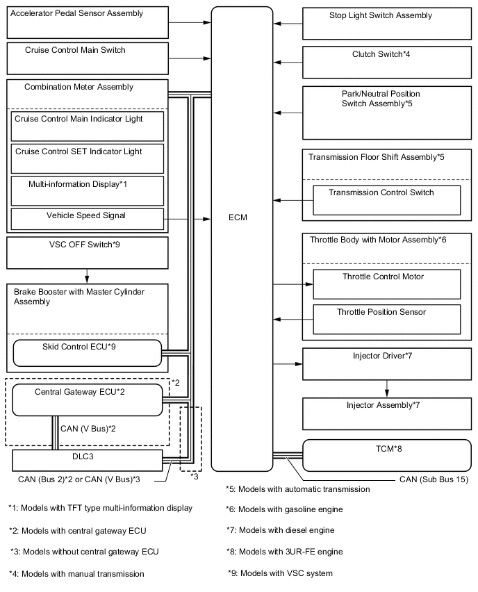
Part of the circuit has been altered along with the new Controller Area Network (CAN) communication system.
Figure 1. System Diagram
-
-
Layout of Main Components
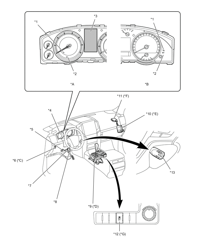
*A Models with TFT type Multi-information Display *B Models with LCD type Multi-information Display *C Models with Manual Transmission *D Models with Automatic Transmission *E Models with 3UR-FE Engine *F Models with Central Gateway ECU *G Models with VSC System - - *1 Cruise Control Main Indicator Light *2 Cruise Control SET Indicator Light *3 Multi-information Display *4 Combination Meter Assembly *5 Stop Light Switch Assembly *6 Clutch Switch *7 DLC3 *8 Accelerator Pedal Sensor Assembly *9 Transmission Floor Shift Assembly
-
Transmission Control Switch
*10 TCM *11 Central Gateway ECU *12 VSC OFF Switch *13 Cruise Control Main Switch - - 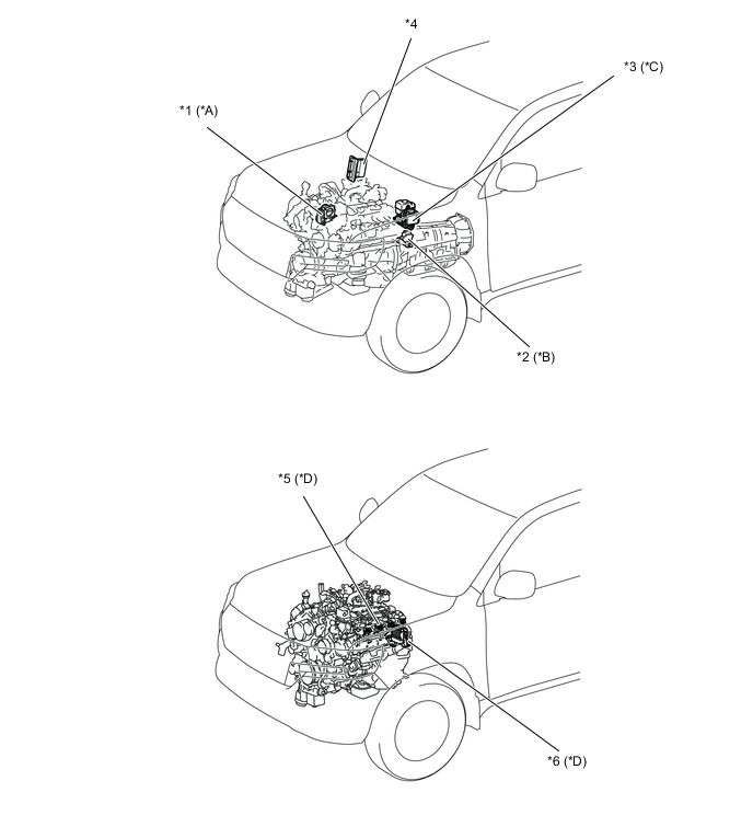
*A Models with Gasoline Engine *B Models with Automatic Transmission *C Models with VSC System *D Models with Diesel Engine *1 Throttle Body with Motor Assembly
-
Throttle Control Motor
-
Throttle Position Sensor
*2 Park/Neutral Position Switch Assembly *3 Brake Booster with Master Cylinder Assembly
-
Skid Control ECU
*4 ECM *5 Injector Assembly *6 Injector Driver -
-
System Control
-
Conditions on VSC and TRC have been added to the conditions for Manual Cancel Control.*
*: Models with VSC system
Control Outline Manual Cancel Control If any of the following signals is sent to the ECM, the cruise control is canceled accordingly. However, the set speed remains in the memory.
-
VSC is activated.*
-
TRC is activated for a period of time.*
-
When the VSC or TRC system is turned off by pressing the VSC OFF switch.*
*: Models with VSC system
-
-
-