NEW FEATURES
-
DESCRIPTION
-
The blind spot monitor system performs 2 functions using the same blind spot monitor sensors: blind spot monitor function and Rear Cross Traffic Alert (RCTA) function*.
-
*: Models wiht RCTA function
-
-
For except models for Europe, the blind spot monitor system performs 2 functions using the same blind spot monitor sensors: blind spot monitor function and Rear Cross Traffic Alert (RCTA) function*.
-
*: Models wiht RCTA function
-
-
The blind spot monitor function can be enabled or disabled using the blind spot monitor main switch. When the blind spot monitor main switch is turned on, the RCTA function* can be turned off individually by using the RCTA customizing switch.
-
*: Models wiht RCTA function
-
-
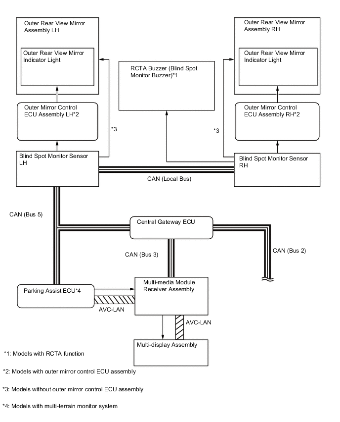
The blind spot monitor system consists of the 2 blind spot monitor sensors, steering sensor, airbag sensor assembly, outer rear view mirror assembly LH and RH, RCTA buzzer (blind spot monitor buzzer)*, combination meter assembly and multi-display assembly etc.
-
*: Models wiht RCTA function
-
-
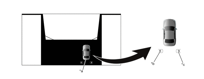
The blind spot monitor function uses sensors to detect vehicles that are traveling in the vehicle's blind spot, helping the driver to confirm safety when changing lanes.
Figure 1. Blind Spot Monitor Function
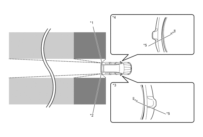
*1 Blind Spot Monitor Sensor LH *2 Blind Spot Monitor Sensor RH *3 Outer Rear View Mirror Assembly RH *4 Outer Rear View Mirror Assembly LH *5 Outer Rear View Mirror Indicator Light - - 
Detection Area (for Vehicle in Blind Spot) 
Detection Area (for Rapidly Approaching Vehicle from Behind) -
If the RCTA function detects a vehicle in the rear side direction while the driver is reversing in a parking lot, the function alerts the driver by sounding the rear cross traffic alert buzzer and flashing the outer rear view mirror indicators light to provide information for the driver, supporting decision making.*
-
*: Models wiht RCTA function
Figure 2. RCTA Function
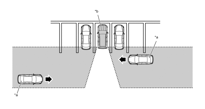
*a Target Vehicle *b This Vehicle Detection Area - - -
-
For except models for Europe, the blind spot monitor system performs 2 functions using the same blind spot monitor sensors: blind spot monitor function and Rear Cross Traffic Alert (RCTA) function*.
-
*: Models wiht RCTA function
-
-
-
PRECAUTIONS
-
Cautions regarding the use of the system
-
The driver is solely responsible for safe driving. Always drive safely, taking care to observe your surroundings.
-
The blind spot monitor function is a supplementary function which alerts the driver that a vehicle is in a blind spot of the outside rear view mirrors or is approaching rapidly from behind into a blind spot. Do not overly rely on the blind spot monitor function. As the function cannot judge if it is safe to change lanes, over reliance could lead to an accident resulting in death or serious injury. As the system may not function correctly under certain conditions, the driver's own visual confirmation of safety is necessary.
-
The RCTA function is only a supplementary function which alerts the driver that a vehicle is approaching from the right or left at the rear of the vehicle. As the RCTA function may not function correctly under certain conditions, the driver's own visual confirmation of safety is necessary. Over reliance on this function may lead to an accident resulting death or serious injury.
-
-
Outside rear view mirror indicator visibility
-
In strong sunlight, the outside rear view mirror indicator may be difficult to see.
-
-
Hearing the RCTA buzzer
-
The RCTA buzzer may be difficult to hear over loud noises such as if the audio system volume is high.
-
-
The blind spot monitor function is not designed to detect the following types of vehicles and/or objects:
-
Small motorcycles, bicycles, pedestrians, etc.*
-
Vehicles traveling in the opposite direction.
-
Guardrails, walls, signs, parked vehicles and similar stationary objects.*
-
Following vehicles that are in the same lane.*
-
Vehicles traveling 2 lanes away from this vehicle.
-
*: Depending on conditions, detection of a vehicle and/or object may occur.
Tech Tips
In this section, the expression "this vehicle" is used to refer to the vehicle equipped with this blind spot monitor system.
-
-
-
The blind spot monitor function may not detect vehicles correctly in the following situations:
-
When the sensor is misaligned due to a strong impact to the sensor or its surrounding area.
-
When mud, snow, ice, a sticker, etc. is covering the sensor or surrounding area on the rear bumper.
-
When driving on a road surface that is wet with standing water during bad weather such as heavy rain, snow, or fog.
-
When multiple vehicles are approaching with only a small gap between each vehicle.
-
When the distance between this vehicle and a following vehicle is short.
-
When there is a significant difference in speed between this vehicle and the vehicle that enters the detection area.
-
When the difference in speed between this vehicle and another vehicle is changing.
-
When a vehicle enters a detection area traveling at about the same speed as this vehicle.
-
As this vehicle starts from a stop, a vehicle remains in the detection area.
-
When driving up and down consecutive steep inclines, such as hills, dips in the road, etc.
-
When driving on roads with sharp bends, consecutive curves, or uneven surfaces.
-
When vehicle lanes are wide, or when driving on the edge of a lane, and the vehicle in an adjacent lane is far away from this vehicle.
-
When a bicycle carrier or other accessory is installed to the rear of the vehicle.
-
When there is a significant difference in height between this vehicle and the vehicle that enters the detection area.
-
Immediately after the blind spot monitor main switch is turned on.
Tech Tips
In this section, the expression "this vehicle" is used to refer to the vehicle equipped with this blind spot monitor system.
-
-
Instances of the blind spot monitor function unnecessarily detecting a vehicle and/or object may increase under the following situations:
-
When the sensor is misaligned due to a strong impact to the sensor or its surrounding area.
-
When the distance between this vehicle and a guardrail, wall, etc. that enters the detection area is short.
-
When driving up and down consecutive steep inclines, such as hills, dips in the road, etc.
-
When vehicle lanes are narrow, or when driving on the edge of a lane, and a vehicle traveling in a lane other than the adjacent lanes enters the detection area.
-
When driving on roads with sharp bends, consecutive curves, or uneven surfaces.
-
When the tires are slipping or spinning.
-
When the distance between this vehicle and a following vehicle is short.
-
When a bicycle carrier or other accessory is installed to the rear of the vehicle.
Tech Tips
In this section, the expression "this vehicle" is used to refer to the vehicle equipped with this blind spot monitor system.
-
-
The RCTA function is not designed to detect the following types of vehicles or objects:
-
Vehicles approaching from directly behind.
-
Vehicles backing up in a parking space next to this vehicle.
-
Vehicles that the sensors cannot detect due to obstructions
-
Guardrails, walls, signs, parked vehicles and similar stationary objects.*
-
Small motorcycles, bicycles, pedestrians, etc.*
-
Vehicles moving away from this vehicle.
-
Vehicles approaching from the parking spaces next to this vehicle.*
-
*: Depending on conditions, detection of a vehicle and/or object may occur.
Tech Tips
In this section, the expression "this vehicle" is used to refer to the vehicle equipped with this blind spot monitor system.
-
-
-
The RCTA function may not detect vehicles correctly in the following situations:
-
When the sensor is misaligned due to a strong impact to the sensor or its surrounding area.
-
When mud, snow, ice, a sticker, etc. is covering the sensor or surrounding area on the rear bumper.
-
When driving on a road surface that is wet with standing water during bad weather such as heavy rain, snow, or fog.
-
When multiple vehicles are approaching with only a small gap between each vehicle.
-
When a vehicle is approaching at high speed.
-
When backing up on a slope with a sharp change in grade.
-
When backing out of a shallow angle parking spot.
-
Immediately after the blind spot monitor main switch is turned on.
-
Immediately after the engine is started with the blind spot monitor main switch on.
-
When the sensors cannot detect a vehicle due to obstructions.
Tech Tips
In this section, the expression "this vehicle" is used to refer to the vehicle equipped with this blind spot monitor system.
-
-
Instances of the RCTA function unnecessarily detecting a vehicle and/or object may increase under the following condition:
-
When a vehicle passes by the side of this vehicle.
-
When the parking space faces a street and vehicles are being driven on the street.
-
When the distance between this vehicle and metal objects, such as a guardrail, wall, sign, or parked vehicle, which may reflect electrical waves toward the rear of the vehicle, is short.
Tech Tips
In this section, the expression "this vehicle" is used to refer to the vehicle equipped with this blind spot monitor system.
-
-
Blind spot monitor sensors are installed inside the left and right side of the vehicle rear bumper respectively. Observe the following to ensure the blind spot monitor system can function correctly.
-
Keep the sensors and the surrounding areas on the rear bumper clean at all times.
-
Do not subject a sensor or its surrounding area on the rear bumper to a strong impact. If a sensor is moved even slightly off position, the system may malfunction and vehicles may not be detected correctly. In the following situations, have this vehicle inspected by your Toyota dealer.
-
A sensor or its surrounding area is subject to a strong impact.
-
If the surrounding area of a sensor is scratched or dented, or part of them has become disconnected.
-
-
Do not disassemble the sensor.
-
Do not attach stickers to the sensor or surrounding area on the rear bumper.
-
Do not modify the sensor or surrounding area on the rear bumper.
-
Do not paint the rear bumper any color other than an official Toyota color.
Tech Tips
In this section, the expression "this vehicle" is used to refer to the vehicle equipped with this blind spot monitor system.
-
-
Under the following condition, the blind spot monitor system may store DTCs C1AC1 and C1AC2 by mistake:
-
The vehicle is driven continuously with the blind spot monitor main switch on when using a drum tester such as a speedometer tester, brake/ speedometer combination tester or chassis dynamometer.
-
When mud, snow, ice, a sticker, etc. is covering the sensor or surrounding area on the rear bumper.
-
-
-
SYSTEM DIAGRAM
-
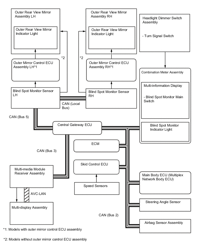
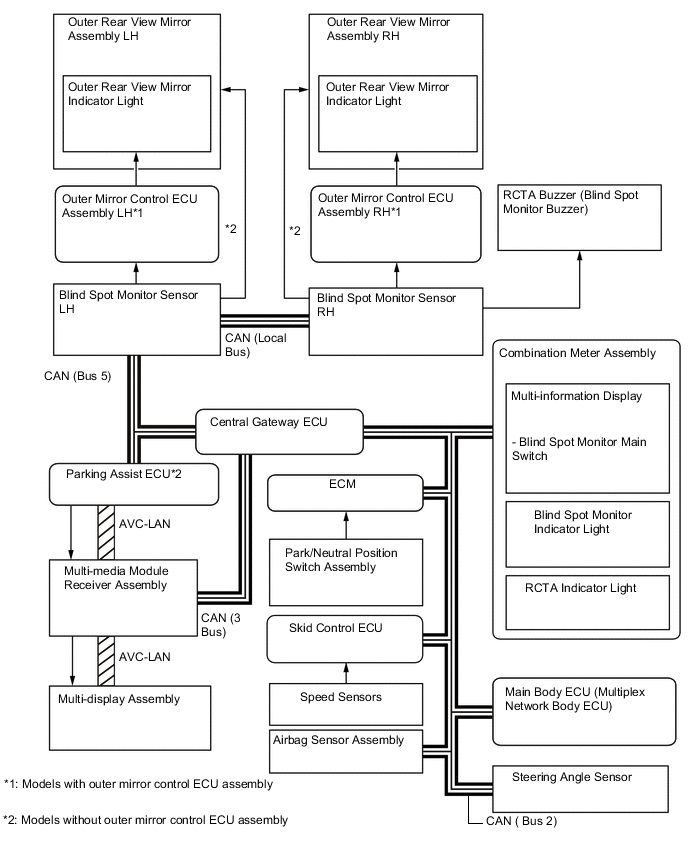
LAYOUT OF MAIN COMPONENTS
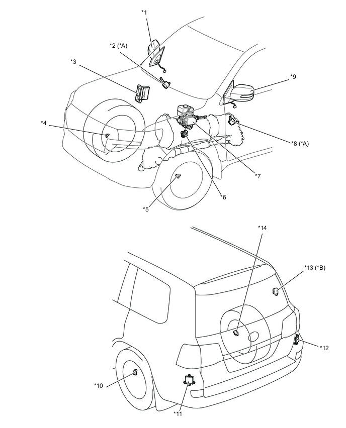
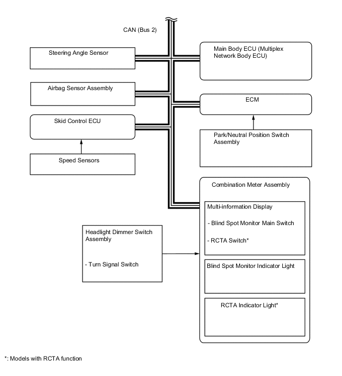
*A Models with outer mirror control ECU assembly *B Models with RCTA function *1 Outer Rear View Mirror Assembly RH *2 Outer Mirror Control ECU Assembly RH *3 ECM *4 Front Speed Sensor RH *5 Front Speed Sensor LH *6 Park/Neutral Position Switch Assembly *7 Skid Control ECU *8 Outer Mirror Control ECU Assembly LH *9 Outer Rear View Mirror Assembly LH *10 Rear Speed Sensor LH *11 Blind Spot Monitor Sensor LH *12 Blind Spot Monitor Sensor RH *13 RCTA Buzzer (Blind Spot Monitor Buzzer) *14 Rear Speed Sensor RH 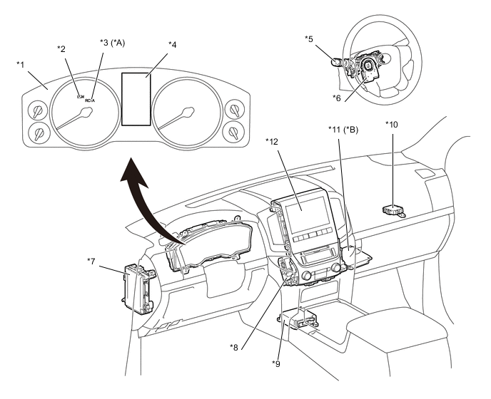
*A Models with RCTA function *B Models with multi-terrain monitor system *1 Combination Meter Assembly *2 Blind Spot Monitor Indicator Light *3 Rear Cross Traffic Alert Indicator Light *4 Multi-information Display *5 Headlight Dimmer Switch Assembly *6 Steering Angle Sensor *7 Main Body ECU (Multiplex Network Body ECU) *8 Multi-media Module Receiver Assembly *9 Airbag Sensor Assembly *10 Central Gateway ECU *11 Parking Assist ECU *12 Multi-display Assembly -
FUNCTION OF MAIN COMPONENTS
Component Function Blind Spot Monitor Sensor LH and RH
-
Outputs millimeter waves from the blind spot monitor sensor to the blind spot sensor detection area, uses the reflected millimeter waves for detecting the presence of a vehicle, the vehicle-to-vehicle distance, and the relative speed, and then transmits this information to the built-in signal processing circuit.
-
The signal processing circuit determines if a vehicle is present, and illuminates or blinks the outer rear view mirror indicator accordingly.
-
Dims the outer rear view mirror indicator light on the outer rear view mirror assembly.
-
Transmits the indicator light signal to the outer mirror control ECU assembly LH/RH.
Outer Rear View Mirror Assembly
-
Outer Rear View Mirror Indicator Light
-
Illuminates when a vehicle is detected in the detection area (blind spot monitor function).
-
Blinks when the turn signal switch is operated while a vehicle is detected in the detection area (blind spot monitor function).
-
Blinks when another vehicle is detected in the alert area while the vehicle is backing up (RCTA function).*1
Outer Mirror Control ECU Assembly (LH and RH)*2 Transmits the indicator light signal to the outer rear view mirror assembly. Headlight Dimmer Switch Assembly
-
Turn Signal Switch
Transmits the turn signal switch signal to the combination meter assembly. Combination Meter Assembly Multi-information Display
-
Blind Spot Monitor Main Switch
-
RCTA Switch
-
Displays "Blind Spot Monitor System Malfunction Visit Your Dealer" when the blind spot monitor system malfunctions and "Blind Spot Monitor Unavailable" when the system cannot be used temporarily to inform the driver.
-
The blind spot monitor main switch turns the blind spot monitor function and RCTA function*1 on or off. The blind spot monitor function and the RCTA function*1 are turned on or off simultaneously.
-
The RCTA switch turns only the RCTA function *1 on or off.*3
Blind Spot Monitor Indicator Light Illuminates when the blind spot monitor system is turned on and goes out when the system is turned off in order to inform the driver of the system status. RCTA Indicator Light*1 Illuminates when the RCTA function is turned on and goes out when the system is turned off in order to inform the driver of the system status. Multi-display Assembly Displays signals from the multi-media module receiver assembly on the screen. Multi-media Module Receiver Assembly Sends information to the multi-display when obstacles are detected. Skid Control ECU Transmits the vehicle speed signal to the blind spot monitor sensors LH and RH. Main Body ECU (Multiplex Network Body ECU) Transmits the destination signal, illumination signal and dimmer signal to the blind spot monitor sensor LH and RH. ECM Transmits the reverse signal to the blind spot monitor sensors LH and RH. RCTA Buzzer (Blind Spot Monitor Buzzer)*1 Sounds when a vehicle is detected in the blind spot monitor sensor detection area while the driver is reversing. Airbag Sensor Assembly Outputs yawrate information to the blind spot monitor sensor LH and RH. Steering Angle Sensor Transmits the steering angle signal to the blind spot monitor sensor LH and RH. Network Gateway ECU Transmits data between the CAN (bus 2), CAN (bus 5) and CAN (bus 3). Speed Sensors Detects the wheel speed of each of the 4 wheels. Parking Assist ECU*4 Outputs the cooperative display video signal for the multi-terrain monitor screen to the multi-media module receiver assembly based on signals from the blind spot monitor sensor LH and RH. Park/Neutral Position Switch Assembly Transmits the shift position signal to the ECM. *1: Models with RCTA function
*2: Models with outer mirror control ECU assembly
*3: The RCTA switch will function when the blind spot monitor main switch is on.
*4: Models with multi-terrain monitor system
-
-
CONSTRUCTION AND OPERATION
-
Blind Spot Monitor Function
-
The blind spot monitor function operates when both of the following conditions are met:
-
The blind spot monitor main switch is on.
-
The shift lever is in a position other than R.
-
The vehicle speed is greater than approximately 16 km/h (10 mph).
-
-
The blind spot monitor function can detect vehicles in its detection areas.
-
The detection areas formed by the blind spot monitor sensors LH and RH are as shown below:
Tech Tips
If another vehicle that is rapidly approaching the vehicle's blind spot is detected, the notification timing is determined by the relative speed of the approaching vehicle. The notification timing for vehicles rapidly approaching the vehicle's blind spot can be customized. For details, refer to the Repair Manual.
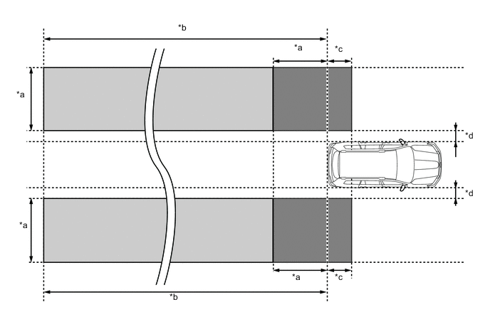
*a 3.0 m (9.8 ft.) *b 60 m (197 ft.) *c 1.0 m (3.3 ft.) *d 0.5 m (1.6 ft.) -
-
Detection Area (for Vehicle in Blind Spot)
-
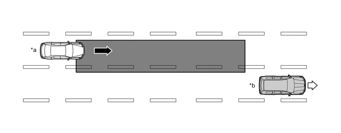
When this vehicle is overtaken by another vehicle in an adjacent lane.
*a Other Vehicle *b This Vehicle 
Vehicle Speed (Fast) 
Vehicle Speed (Slow) Detection Area - - -
When another vehicle enters the detection area of this vehicle due to a lane change.
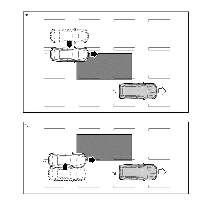
*a The other vehicle enters the detection area during lane change (merge in) (Type 1). *b The other vehicle enters the detection area during lane change (merge in) (Type 2). *c Other Vehicle *d This Vehicle Motion direction of other vehicle Motion direction of this vehicle Detection Area - -
-
-
Detection Area (for Rapidly Approaching Vehicle from Behind)
-
When another vehicle is rapidly approaching from behind.
*a Other Vehicle *b This Vehicle Vehicle Speed (Fast) Vehicle Speed (Slow) Detection Area - - -
When another vehicle enters the detection area of this vehicle due to a lane change and approaches this vehicle.
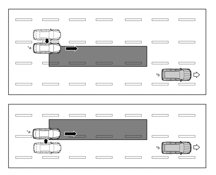
*a Other Vehicle *b This Vehicle Motion direction of other vehicle Motion direction of this vehicle Detection Area - -
-
-
According to operation conditions, the blind spot monitor function promotes safety confirmation by using the outer rear view mirror indicator light to inform the driver that the system detects vehicles that are in or rapidly approaching the vehicle's blind spot.
-
The outer rear view mirror indicator light illuminates when a vehicle is in or rapidly approaching the vehicle's blind spot and the turn light switch is not operated. The indicator light flashes when a vehicle is in or rapidly approaching the vehicle's blind spot and the turn light switch is operated.
-
-
RCTA Function
-
The RCTA function operates when both of the following conditions are met:
-
The blind spot monitor main switch is on.
-
The RCTA switch is on.
-
The Shift lever position is R.
-
The speed of this vehicle is less than approximately 8 km/h (5 mph).
-
Target vehicle's speed is between approximately 8 km/h (5 mph) and 28 km/h (18 mph).
-
-
The RCTA function can detect vehicles in its detection areas.
-
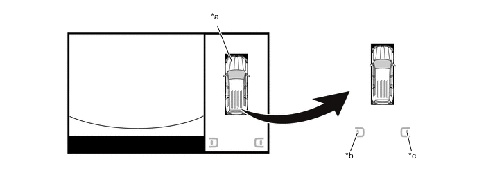
The system continuously measures the relative speed of an approaching vehicle and its distance. If it is determined that the approaching vehicle will cross in the path of this vehicle, the Estimated Crossing Time (ECT) is calculated. When the ECT is 2.5 seconds or less, the system alerts the driver by flashing the outer rear view mirror indicator lights, illuminating the indicator in the multi-display assembly, and sounding the RCTA buzzer (blind spot monitor buzzer).
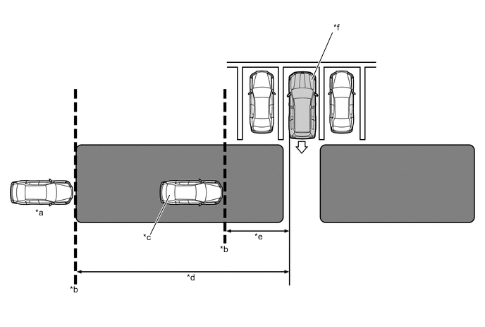
*a Target Vehicle (Approximately 28 km/h (18 mph)) *b Target Detection Line *c Target Vehicle (Approximately 8 km/h (5 mph)) Approximately 20 m (66 ft.) *d Approximately 20 m (66 ft.) *e Approximately 5.5 m (18.0 ft.) *f This Vehicle Alert Area - - -
-
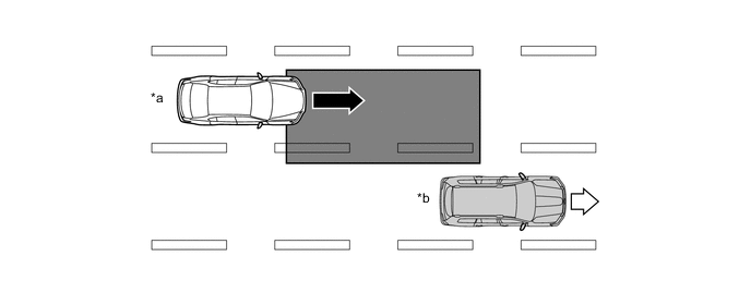
Normal Parking
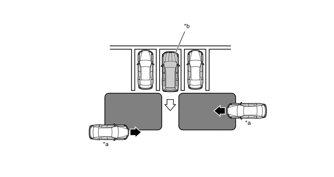
*a Target Vehicle *b This Vehicle Alert Area - - -
According to operation conditions, the RCTA function promotes safety confirmation by using the outer rear view mirror indicator lights and the RCTA buzzer (blind spot monitor buzzer) to inform the driver that another vehicle has entered the blind spot monitor sensor alert area of this vehicle.
-
When this vehicle is reversing, if a vehicle enters the detection area of the blind spot monitor sensors and it is determined the vehicle will cross the path of this vehicle, the system alerts the driver by flashing the outer rear view mirror and multi-display assembly indicator lights and sounding the RCTA buzzer (blind spot monitor buzzer).
-
-
Multi-Display
-
If an approaching vehicle is detected in the detection area when the parking assist monitor system*1 and the multi-terrain monitor system*2 is activated, the direction of the approaching vehicle is displayed on the multi-display assembly.
-
*1: Models with parking assist monitor system
-
*2: Models with multi-terrain monitor system
Figure 3. Wide Rear View, and Side and Rear View (when outer rear view mirror assemblies are retracted)
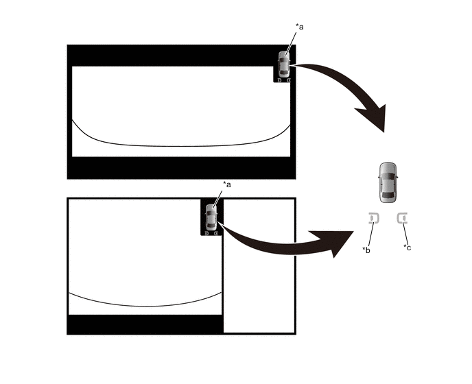
*a Vehicle Icon *b LH Side *c RH Side - - Tech Tips
The illustration shown is an example only. The illustration may differ from the actual vehicle screen.
Figure 4. Wide Rear View and Side Simultaneous View
*a Vehicle Icon *b LH Side *c RH Side - - Tech Tips
The illustration shown is an example only. The illustration may differ from the actual vehicle screen.
Figure 5. Panoramic View
*a Vehicle Icon *b LH Side *c RH Side - - Tech Tips
The illustration shown is an example only. The illustration may differ from the actual vehicle screen.
-
-
The following item displayed on the multi-display is a warning of a system malfunction.

Tech Tips
The illustration shown is an example only. The illustration may differ from the actual vehicle screen.
-
-
Blind Spot Monitor Sensor
-
The blind spot monitor sensor consists of a millimeter wave radar circuit and a signal processing circuit.
-
The millimeter wave radar uses frequencies in the 24 GHz band.
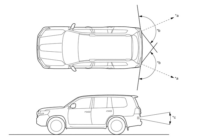
*a Approx. 70 m (230 ft.) *b Approx. 150° *c Approx. 20° - - -
The distance to the object, azimuth and relative speed are calculated from the information that is provided by the reflected millimeter wave radar as described below:
Item Calculation Method Distance Calculated from the length of time that has elapsed from the time the waves of the millimeter wave radar have been emitted, until the reflected waves are received by the millimeter wave radar circuit. The distance is approx. 70 m (230 ft.). Azimuth Calculated from the reception angle of the millimeter wave radar reflections received. The detection angle has a horizontal range of approx. 150° and a vertical range of approx. 20°. Relative Speed Calculated by utilizing the change (Doppler effect*) that occurs in the frequency of the reflected millimeter wave radar waves. Tech Tips
*: The Doppler effect causes the observer to perceive the radio waves emitted by a moving object to be a higher frequency as it approaches, and to be a lower frequency as it recedes. This phenomenon is created because when an object is located far away, the radio waves are perceived at higher frequencies than those of the radio source. An SST is used if radar axis confirmation is needed. For details, refer to the Repair Manual.
-
-