NEW FEATURES
-
DESCRIPTION
-
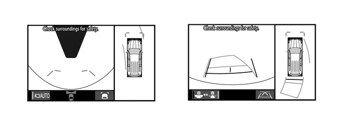
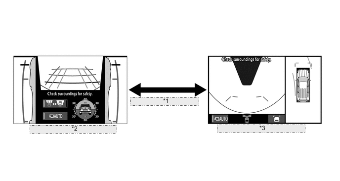
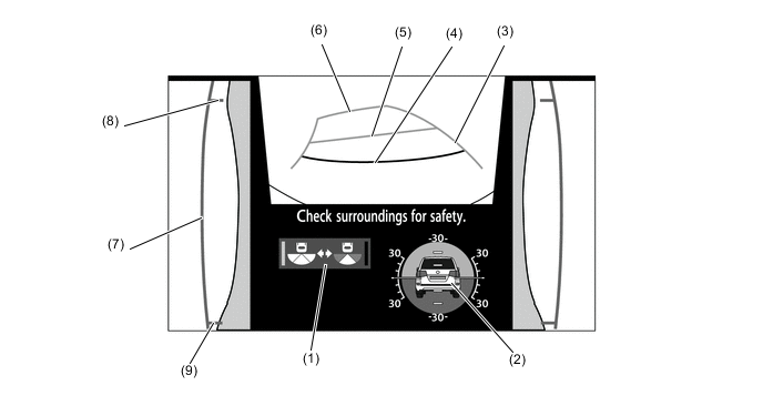
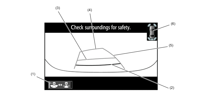
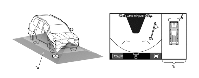
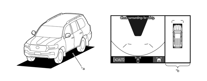
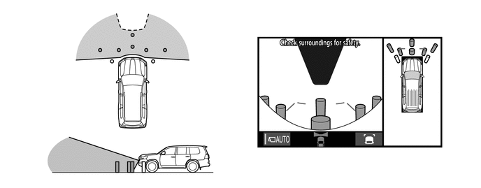
A panoramic view mode is used for the multi-terrain monitor system. As a result, not only driving off-road, but parking on normal roads has become easier.
-
An under vehicle terrain view and side simultaneous view mode are used for the multi-terrain monitor system. With the under vehicle terrain view, the condition of the vehicle underfloor and tire positions, which could not be confirmed before, can be confirmed on the screen.
-
With the front view, underfloor and side simultaneous view mode, a rotating screen function is used to show the front view screen according to the tilt of the vehicle. As a result, the driver can sense the tilt of the vehicle.
-
-
SYSTEM DIAGRAM
-
LAYOUT OF MAIN COMPONENTS
*A Models with Blind Spot Monitor System - - *1 Side Television Camera Assembly RH *2 ECM *3 Front Television Camera Assembly *4 Park/Neutral Position Switch Assembly *5 Side Television Camera Assembly LH *6 Skid Control ECU *7 Blind Spot Monitor Sensor LH - - 
*A Modelswith VGRS System *B Models with Toyota Parking Assist-sensor System *1 Steering Sensor *2 Multi-display Assembly *3 Main Switch Assembly (Camera Switch) *4 Main Body ECU (Multiplex Network Body ECU) *5 Steering Control ECU *6 Outer Mirror Switch Assembly *7 Airbag Sensor Assembly *8 Multi-media Module Receiver Assembly *9 Parking Assist ECU *10 Clearance Warning ECU Assembly *11 4 Wheel Drive Control ECU - - -
FUNCTION OF MAIN COMPONENTS
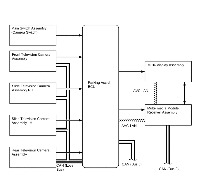
Component Function Multi-display Assembly Receives information from the parking assist ECU and multi-media module receiver assembly and displays various screens on the multi-display assembly. Multi-media Module Receiver Assembly Sends information from the parking assist ECU, etc. to the multi-display assembly. Skid Control ECU Sends vehicle speed information and slip information signals to the parking assist ECU. Television Camera Assemblies Installed on the front grille, outer rear view mirror assembly and back door and send an image signal to the parking assist ECU. Main Body ECU (Multiplex Network Body ECU) Sends door courtesy switch information and mirror contracted state information signals to the parking assist ECU. Parking Assist ECU
-
Receives information from various ECUs and sensors to control the multi-terrain monitor system.
-
Sends information from various ECUs to each television camera assembly.
ECM Outputs a shift position signal to the parking assist ECU. Steering Sensor Detects the angle of the steering wheel and sends the resulting signals to the parking assist ECU. Main Switch Assembly (Camera Switch) Switches the screen displays. 4 Wheel Drive Control ECU Sends the transfer range information to the parking assist ECU. Blind Spot Monitor SensorLH* Sends the detection information to the parking assist ECU. Airbag Sensor Assembly Sends the yaw rate information and G sensor information to the parking assist ECU. *: Models with blind spot monitor system
-
-
CONSTRUCTION AND OPERATION
-
Television Camera Assembly
-
The television camera assemblies consists of a screen input component with a wide-angle lens and avideo signal output component with a small type color Complementary Metal Oxide Semiconductor(CMOS) camera.
*1 Front Television Camera Assembly *2 Side Television Camera Assembly LH *3 Side Television Camera Assembly RH *4 Rear Television Camera Assembly
-
-
-
OPERATION CONDITION
-
The multi-terrain monitor system (manual display mode) will display under the following conditions:
-
Engine switch is on (IG).
-
Vehicle speed is 20 km/h (12.4 mph) or less.
-
Shift lever is moved to P, D or N
-
-
The multi-terrain monitor system (auto display mode) will display under the following conditions:
-
Engine switch is on (IG).
-
Auto mode is on.
-
Shift lever is moved to D or N.
-
Vehicle speed has become 10 km/h (6.2 mph) or less and the shift lever is not in R.
-
-
-
FUNCTION
-
General
-
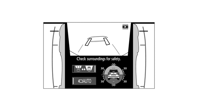
The multi-terrain monitor system screens displayed on the multi display can be switched by pressingthe main switch assembly (camera switch).
-
When the transfer is in L4 mode, the off-road screen is displayed. When in H4 mode, the on-roadscreen is displayed.
-
The off-road screen displays any of the following: the front view and side simultaneous view mode,front view and side simultaneous view (front enlarged) mode, under vehicle terrain view and sidesimultaneous view (front enlarged) mode, rear view and side simultaneous view mode, or wide rear view mode.
-
The on-road screen displays any of the following: the front view and panoramic view mode, sidesimultaneous view mode, rear view and panoramic view mode, wide rear view mode, wide frontview and panoramic mode (when the outside rear view mirrors are retracted), or rear view and sideview mode (when the outside rear view mirrors are retracted).Transfer Range SwitchingScreen Transition
*1 Transfer Range Switching *2 Screen Transition for Off- road Screens (L4 Mode) *3 Screen Transition for On- road Screens (H4 Mode)
-
Panoramic View Monitor Mode Display Range
-
Panoramic View
-
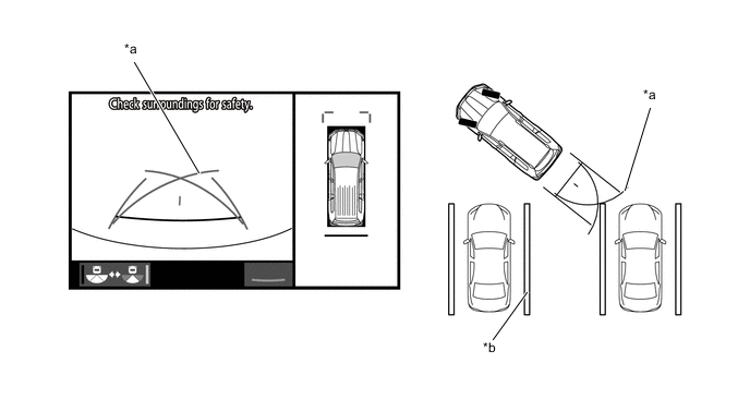
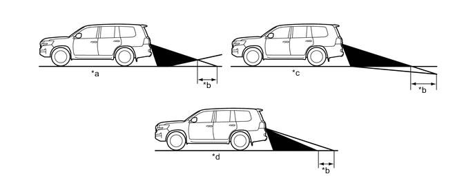
The display range of the panoramic view image is as follows. However, the range differsaccording to the vehicle and road surface conditions.
Note
The panoramic view image display range is limited and objects in the blind spot close to thevehicle or objects taller than the road surface may not be displayed. Also, the clearness at thefour corners may be reduced. Take care when driving.
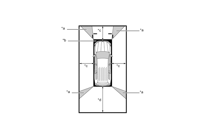
*a Image Combination Processing Area *b Blind Spot *c Approximately 2.0 m (6.6 ft.) *d Approximately 3.0 m (9.8 ft.) -
Wide Front View
-
The wide front view image is an image of the following front television camera assemblyimaging range. However, the range differs according to the vehicle and road surface conditions.
Tech Tips
Since the driver's sense of the distance in front of the vehicle differs from actual conditions,masking (mask area) is used.
Note
The image display range is limited. Also, since objects near either end of the bumper andobjects positioned directly under and near the bumper may not be displayed, take care whendriving.
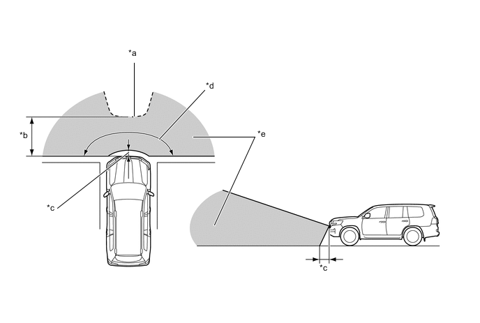
*a Mask Area *b Approximately 5.0 m (16.4 ft.) *c Approximately 0.4 m (1.3 ft.) *d Approximately 180° *e Front Television Camera Assembly Imaging Range - - -
Rear View / Wide Rear View
-
The rear view/wide rear view image is an image of the following rear television cameraassembly imaging range. However, the range differs according to the vehicle and road surfaceconditions.
Note
The image display range is limited. Also, since objects near either end of the bumper andobjects positioned directly under and near the bumper may not be displayed, take care whendriving.
*a Rear Television Camera Assembly Imaging Range (Rear View) *b Rear Television Camera Assembly Imaging Range (Wide Rear View) -
Side Views
-
The side views image is an image of the following side television camera assembly imagingrange. However, the range differs according to the vehicle and road surface conditions.
Note
The image display range is limited, take care when driving.
*a Side Television Camera Assembly Imaging Range - - -
Side View
-
The side view image is an image of the following side television camera assembly imagingrange. However, the range differs according to the vehicle and road surface conditions.
Note
The image display range is limited, take care when driving.
*a Side Television Camera Assembly Imaging Range - -
-
-
Panoramic view Monitor Mode Screen And Operation
-
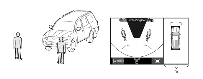
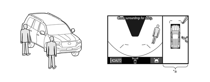
Each screen of the panoramic view displays guide lines, estimated course lines, etc., togetheraccording to the selected screen display mode to inform the driver of the tire positions andtrajectories which cannot be directly seen from the driver seat.
-
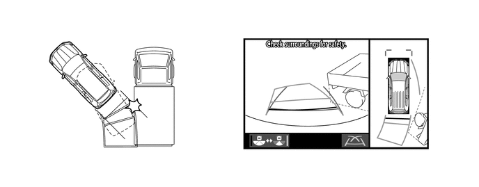
When the Toyota parking assist-sensor system and blind spot monitor system detects an obstacle, obstacle detection information is displayed superimposed on the screen according to each screen display mode.
-
-
Under Vehicle Terrain View Mode Display Range
-
In the under vehicle terrain view mode, a view captured by the front camera when the vehicle wasapproximately 3 m behind its current position is displayed. On top of this image, lines indicating thecurrent vehicle and tire positions are shown.
*a Image Captured Approximately 3 m (9.8 ft.) behind Current Vehicle Position *b Current Vehicle Position *c Vehicle Position when Image Captured - -
-
-
-
DISPLAY TRANSITION
-
The manual display mode of the multi-terrain monitor system undergoes the following screentransitions:
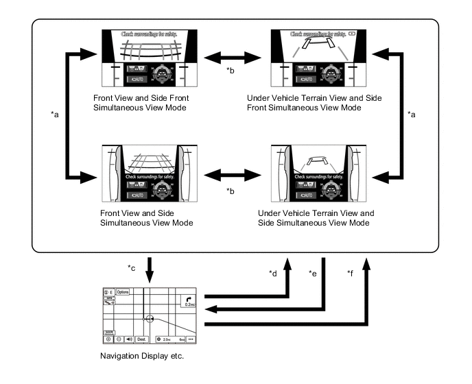
Figure 1. Screen Transition for Off-road Screens (L4 Mode)
*A When Steering Wheel is Turned by 270° or more - - *1 Shift Lever in D or N *2 Zoom Display *3 Normal Condition *4 Shift Lever R Position *5 Front View and Side Front Simultaneous View Mode *6 Under Vehicle Terrain View and Side Front Simultaneous View Mode *7 Rear and Side Views Mode *8 Wide Rear View Mode *9 Navigation Display etc. *10 Front View and Side Simultaneous View Mode *11 Under Vehicle Terrain View and Side Simultaneous View Mode - - Item Transition Condition *a The main switch assembly (camera switch) is operated. *b The main switch assembly (camera switch) is pressed when the shift lever is in D or N. *c The screen selection button is touched. *d The map switch is pressed, or the shift lever is moved to P. *e The shift lever is in a position other than P and R. *f The shift lever is in R. *g The camera angle mode switch button is touched. *h The driver turns the steering wheel less than 90°. *i The driver turns the steering wheel 90° or more. *j The shift lever is moved to P. *k Touch the camera image. Figure 2. Screen Transition for On-road Screens (H4 Mode) 1
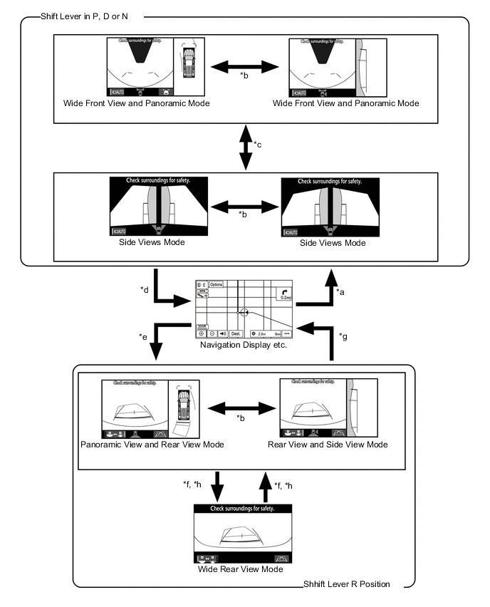
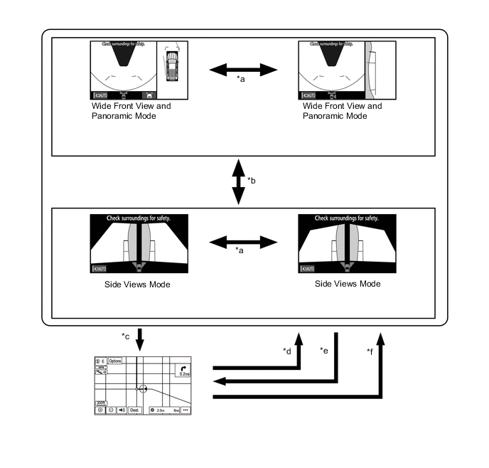
Item Transition Condition *a The main switch assembly (camera switch) is operated. *b The outer mirror switch (open/close) is operated. *c The main switch assembly (camera switch) is pressed when the shift lever is in P, D or N. *d The map switch is pressed, or the shift lever is moved to P. *e The shift lever is in R. *f The camera angle mode switch button is touched. *g The shift lever is moved to P. *h Touch the camera image. Figure 3. Screen Transition for On-road Screens (H4 Mode) 2
*1 Panoramic View and Rear View Mode *2 Wide Rear View Mode *3 Rear and Side Views Mode *4 Wide Front View and Panoramic Mode *5 Estimated Course Line Display Mode *6 Parking Assist Guide Line Mode *7 Distance Guide Line Display Mode - - Item Transition Condition *a The display mode switch button (rear view) is touched. *b The display mode switch button (front view) is touched.
-
The auto display mode of the multi-terrain monitor system undergoes the following screentransitions:
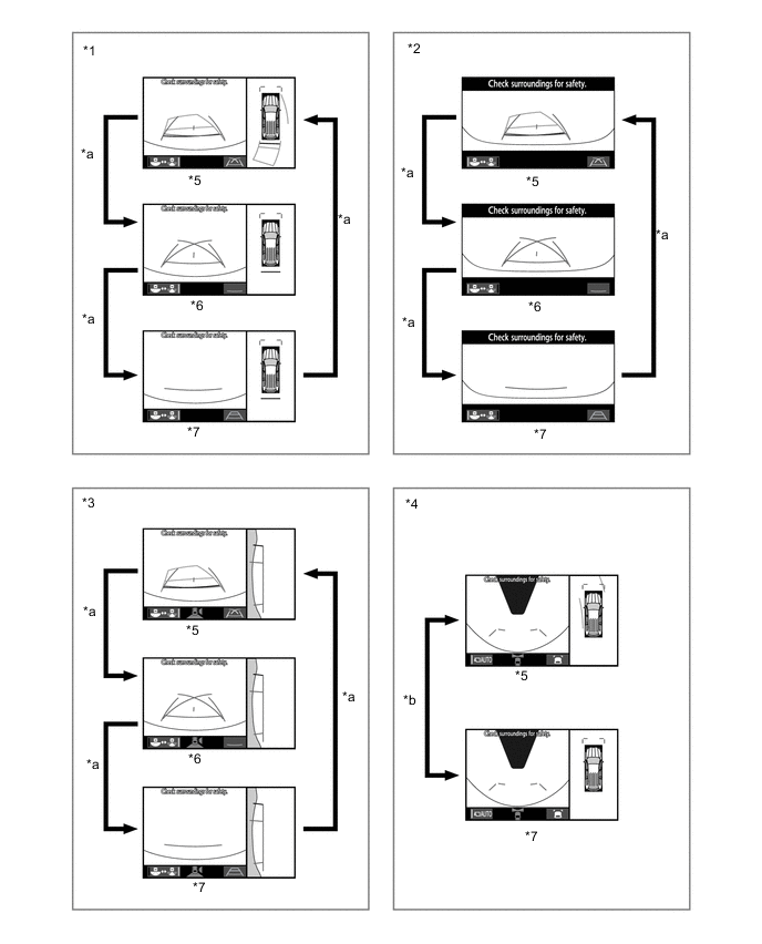
Figure 4. Screen Transition for Off-road Screens (L4 Mode)
Item Transition Condition *a The main switch assembly (camera switch) is operated or display is touched. *b The screen selection button is touched. *c The map switch is pressed when the shift lever is in D or N. *d The vehicle speed has become from more than 10 km/h (6.2 mph) to 10 km/h (6.2 mph) or less. *e The vehicle speed has become from 20 km/h (12.4 mph) or less to more than 20 km/h(12.4 mph). *f The shift lever is moved from P or R to any position other than P and R. Figure 5. Screen Transition for On-road Screens (H4 Mode)
Item Transition Condition *a The outer mirror switch (open/close) is operated. *b The main switch assembly (camera switch) is operated. *c The map switch is pressed when the shift lever is in D or N. *d The vehicle speed has become from more than 10 km/h (6.2 mph) to 10 km/h (6.2 mph) or less. *e The vehicle speed has become from 120 km/h (12.4 mph) or less to more than 20 km/h(12.4 mph). *f The shift lever is moved from P or R to any position other than P and R.
-
Off-Road Screens
-
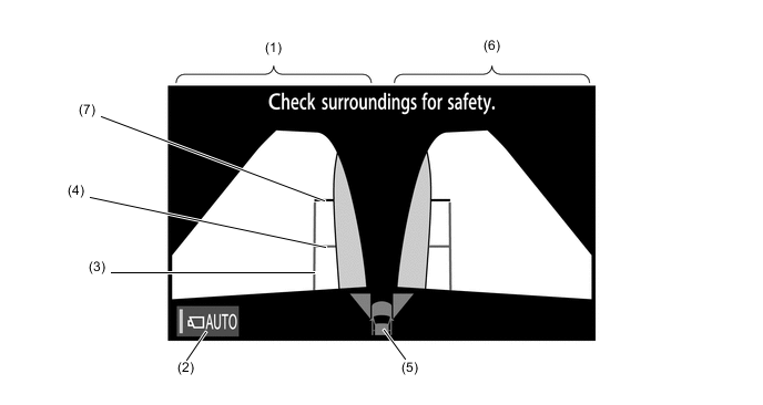
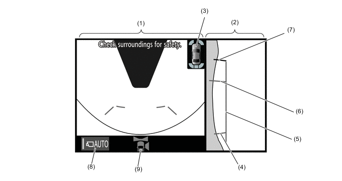
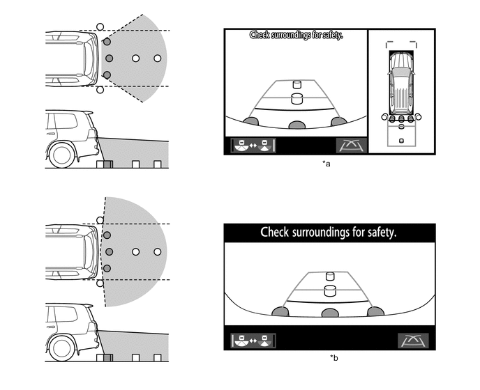
Front View and Side Simultaneous View Mode
-
The front view and side simultaneous view mode displays the front and both sides of thevehicle.
-
A tilt gauge that indicates the vehicle tilt has been added to the screen. Also, when a tire isspinning freely or when the Toyota parking assist-sensor system detects an obstacle, etc.,the tilt gauge is interrupted by another screen.
-
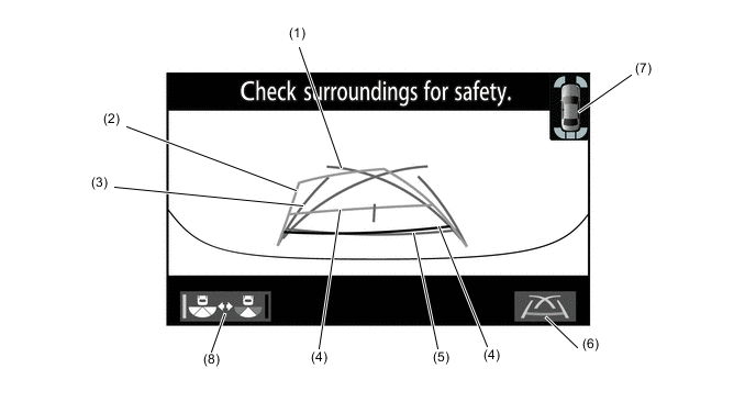
In the front view and side simultaneous view mode, the screen displays as shown in theillustration below:
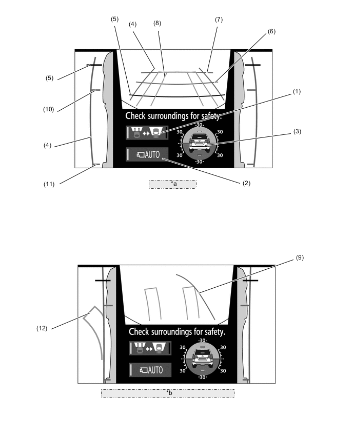
*a Normal Condition *b When Steering Sheel is Turned by 270° or more Item Description (1) Screen Selection Button Switches between the front view and under vehicle terrain view. (2) Automatic Display Mode Selection Button
-
Switches the automatic display mode on/off.
-
When automatic display mode is on, the operation indicator turns on.
(3) Tilt Gauge*1/Interruption Screen*2
-
Displays the vehicle tilt.
-
When a tire is spinning freely or when theToyota parking assist-sensor system*3 detects an obstacle, etc., an interruptionscreen is displayed.
(4) Vehicle Width Parallel Line (Blue) Displays a vehicle width guide line including the outer rear view mirror assemblies. (5) Distance Guide Line (Red) Displays approximately 0.5 m (1.6 ft.) from the front end of the vehicle. (6) Distance Guide Line (Blue) Displays approximately 1.0 m (3.3 ft.) from the front end of the vehicle. (7) Distance Guide Line (Blue) Displays approximately 2.0 m (6.7 ft.) from the front end of the vehicle. (8) Front Wheel Course Lines (Yellow) Displays the projected course of the front tires. (9) Forward Guide Lines (Blue) Displays the course when the vehicle moves forward with the smallest turning radius. (10) Front Wheel Contact Line (Blue) Displays the front wheel positions. (11) Rear Wheel Contact Line (Blue) Displays the rear wheel positions. (12) Rear Wheel Course Lines (Yellow) Displays the projected course of the rear wheels. *1: Models with VSC.
*2: When a tire is spinning freely or when the Toyota parking assist-sensor system detects an obstacle,etc., the tilt gauge is interrupted by another screen.
*3: Models with Toyota parking assist-sensor system
-
-
While the front view and side simultaneous view mode is displayed, the front view can beenlarged by pressing the main switch assembly (camera switch). The enlarged display is shownbelow.
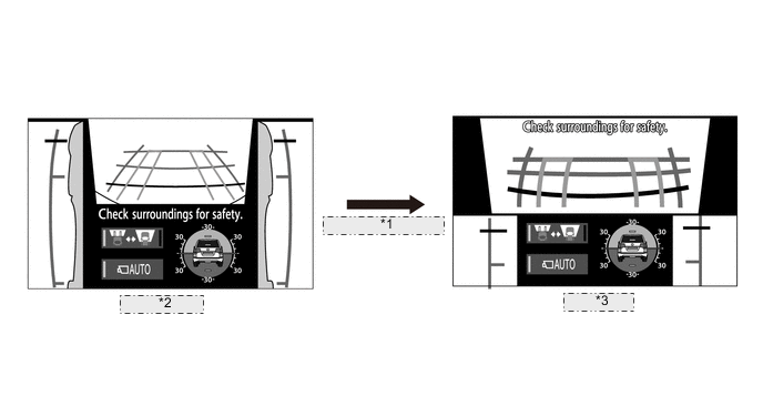
*1 Pressing the main switch assembly (camera switch). *2 Normal screen *3 Zoom Screen -
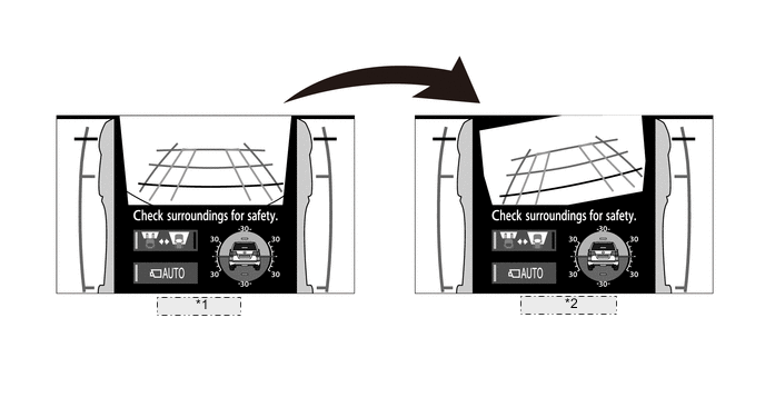
The front view displays a rotating screen that shows the screen according to the tilt of thevehicle.
*1 Normal Screen *2 Rotating Screen -
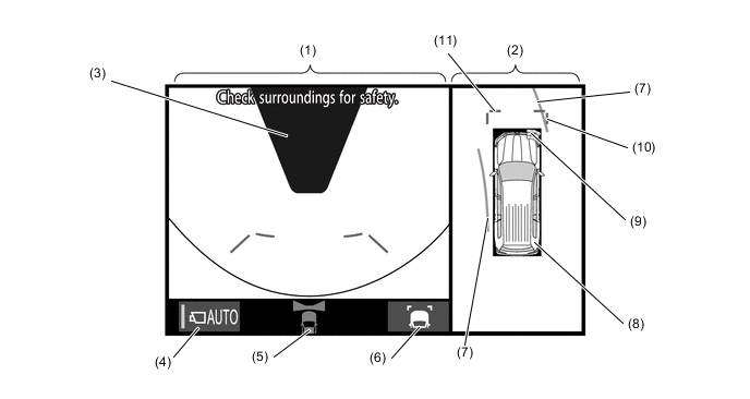
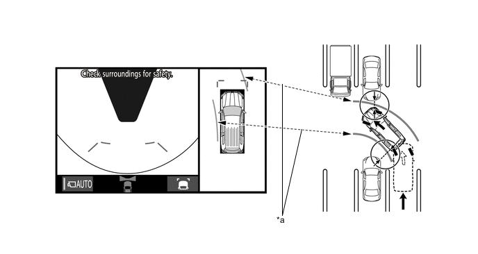
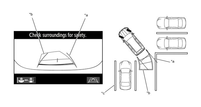
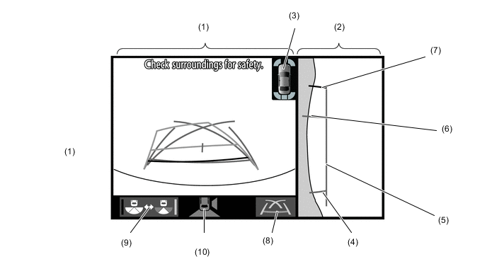
Under Vehicle Terrain View and Side Simultaneous View Mode
-
The under vehicle terrain view and side simultaneous view mode displays the vehicle underfloor(captured image of approximately 3 m (9.8 ft.) behind the current vehicle position) and bothsides of the vehicle.
-
A tilt gauge that indicates the vehicle tilt has been added to the screen. Also, when a tire is spinning freely or when the Toyota parking assist-sensor system detects an obstacle, etc., the tilt gauge is interrupted by another screen.
-
In the under vehicle terrain view and side simultaneous view mode, the screen displays asshown in the illustration below:
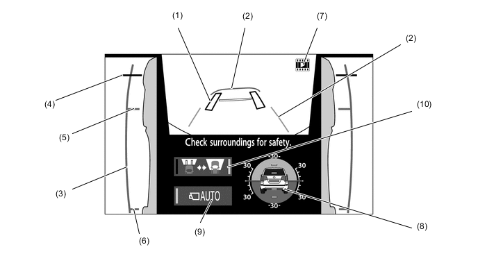
Item Description (1) Tire Position Guide Lines (Black) Displays the current approximate positions of the front wheels. (2) Vehicle Shape Guide Lines (Blue) Displays the current approximate position of the vehicle. (3) Vehicle Width Parallel Line (Blue) Displays a vehicle width guide line including the outer rear view mirror assemblies. (4) Distance Guide Line (Red) Displays approximately 0.5 m (1.6 ft.) from the front end of the vehicle. (5) Front Wheel Contact Line (Blue) Displays the front wheel positions. (6) Rear Wheel Contact Line (Blue) Displays the rear wheel positions. (7) Under Vehicle Terrain View Display Icon An icon indicating that the currently displayed screen is an image captured approximately 3 m (9.8 ft.) behind the current vehicle position. (8) Tilt Gauge*1/InterruptionScreen*2
-
Displays the vehicle tilt.
-
When a tire is spinning freely or when the Toyota parking assist-sensor system*3 detects anobstacle, etc., an interruption screen is displayed.
(9) Automatic Display Mode Selection Button
-
Switches the automatic display mode on/off.
-
When automatic display mode is on, the operation indicator turns on.
(10) Screen Selection Button Switches between the front view and under vehicle terrain view. *1: Models with VSC
*2: When a tire is spinning freely or when the Toyota parking assist-sensor system detects an obstacle,etc., the tilt gauge is interrupted by another screen.
*3: Models with Toyota parking assist-sensor system
-
-
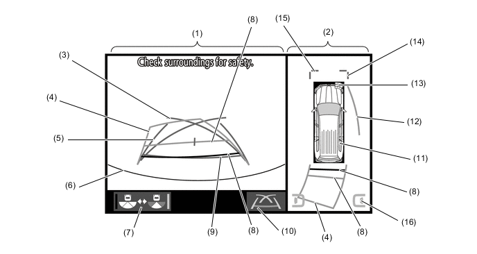
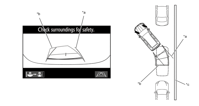
Rear View and Side Simultaneous View Mode
-
The rear view and side simultaneous view mode displays the rear and both sides of the vehicle.
-
A tilt gauge that indicates the vehicle tilt has been added to the screen. Also, when a tire is spinning freely or when the Toyota parking assist-sensor system or RCTA function detects an obstacle, another vehicle, etc., the tilt gauge is interrupted by another screen.
-
The back view and side simultaneous view mode, the screen displays as shown in theillustration below:
Item Description (1) Camera Angle Mode Switch Button Switches between the wide rear view mode and the rear view and side simultaneous view mode. (2) Tilt Gauge*1/InterruptionScreen*2
-
Displays the vehicle tilt.
-
When a tire is spinning freely or when the Toyota parkingassist-sensor system*3 or RCTA function*4 detects anobstacle, another vehicle, etc., the tilt gauge isinterrupted by another screen.
(3) Rear Estimated Course Line (Yellow) Moves in sync with the steering wheel to indicate the estimated reverse course of the vehicle. (4) Distance Guide Line (Red) Displays approximately 0.5 m (1.6 ft.) from the front end of the vehicle. (5) Distance Guide Line (Yellow) Displays approximately 1.0 m (3.3 ft.) from the front end of the vehicle. (6) Distance Guide Line (Yellow) Displays approximately 2.5 m (8.2 ft.) from the front end of the vehicle. (7) Vehicle Width Parallel Line (Blue) Displays a vehicle width guide line including the outer rear view mirror assemblies. (8) Front Wheel Contact Line (Blue) Displays the front wheel positions. (9) Rear Wheel Contact Line (Blue) Displays the rear wheel positions. *1: Models with VSC
*2: When a tire is spinning freely or when the Toyota parking assist-sensor system detects anobstacle, etc., the tilt gauge is interrupted by another screen.
*3: Models with Toyota parking assist-sensor system
*4: Models with blind spot monitor system-
-
-
Wide Rear View Mode
-
The wide rear view mode displays the rear of the vehicle.
-
While the rear view and side simultaneous view mode is displayed, the wide rear view mode isdisplayed by pressing the camera angle mode switch button.
-
In the wide rear view mode, the screen displays as shown in the illustration below:
Item Description (1) Camera Angle Mode Switch Button Switches the Rear view and side simultaneous view mode. (2) Distance Guide Line (Red) Displays approximately 0.5 m (1.6 ft.) from the front end of the vehicle. (3) Distance Guide Line (Yellow) Displays approximately 1.0 m (3.3 ft.) from the front end of the vehicle. (4) Distance Guide Line (Yellow) Displays approximately 2.5 m (8.2 ft.) from the front end of the vehicle. (5) Rear Estimated Course Line (Yellow) Moves in sync with the steering wheel to indicate the estimated reverse course of the vehicle. (6) Interruption Icon*1, *2 Displayed when the Toyota parking assist-sensor system*1 orRCTA function*2 detects an obstacle, another vehicle, etc. *1: Models with Toyota parking assist-sensor system
*2: Models with Blind spot monitor system
-
Tilt Gauge/Interruption Screen
-
A screen that displays the vehicle tilt when the front view and side simultaneous view mode orunder vehicle terrain view and side simultaneous view mode is displayed has been added.
-
The tilt gauge indicates the tilt angle in the longitudinal and lateral directions within 0 ° to 30 °using the vehicle icon and graduations.
-
When a tire is spinning freely, the tilt gauge is interrupted by another screen and the freelyspinning tire is displayed in yellow.
-
When the Toyota parking assist-sensor system or RCTA function detects an obstacle, anothervehicle, etc., the tilt gauge is interrupted by another screen.
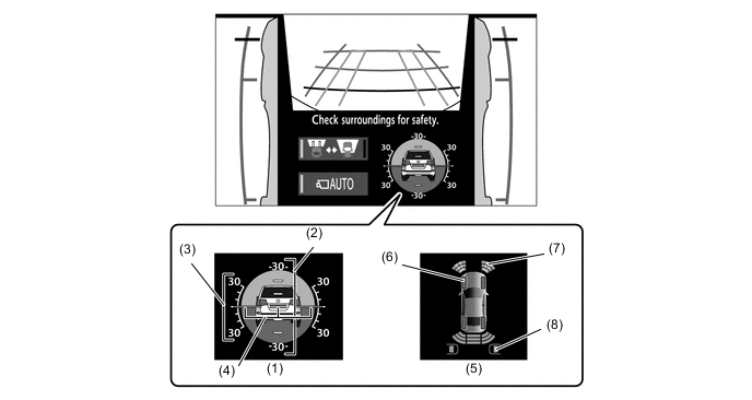
Item Description (1) Tilt Gauge Displays the vehicle state. (2) Longitudinal Tilt Angle Graduations Displays the tilt angle in the longitudinal direction. (3) Lateral Tilt Angle Graduations Displays the tilt angle in the lateral direction. (4) Pointer (Green) Displays the current tilt angle. (5) Interruption Icon When a tire is spinning freely or when the Toyota parking assist-sensor system or RCTA function detects an obstacle, another vehicle, etc., the tilt gauge is interrupted by another screen. (6) Slip Display Shows the freely spinning tires in yellow. (7) Toyota Parking Assist-sensor Display (Models with ToyotaParking Assist-sensorSystem) Indicates when the Toyota parking assist-sensor system detects an obstacle. (8) Blind Spot Monitor Display Indicates when the Rear Cross Traffic Alert (RCTA) function detects an obstacle. Note
-
The tilt angle is shown by the movement of the pointer and the tilt of the vehicleicon.
-
The color of the angle graduations changes depending on the current tilt angle.
-
After the engine switch is turned on (IG), the tilt angle is not indicated until thetilt angle information is verified.
-
The displayed angle may differ from that calculated by other measuring devices.
-
The scale ranges between -35° to +35°, indicating the tilt angle by 5° from thecenter of the vehicle icon
-
-
-
On-Road Screens
-
Side Views Mode
-
The side views mode shows the conditions in the sides of the vehicle.
-
The side views mode, the screen displays as shown in the illustration below:
Item Description (1) Side View (Front Left Side) Screen An image captured by the side television camera assembly LH of the area to the front left side of the vehicle. (2) Automatic Display Mode Selection Button Can be used to turn the automatic display mode on and off. When the automatic display mode is on, an indicator inside the switch illuminates. (3) Vehicle Width Parallel Line (Blue) A vehicle width guide line including the outer rear view mirror assembly. (4) Front Tire Contact Line (Blue) A guide line showing the front tire contact position. (5) Camera Direction Display Vehicle Icon
-
Indicates that the side views screen is displayed.
-
When the Toyota parking assist-sensor system detectsan obstacle, the icon changes to the Toyota parkingassist-sensor system icon.*
(6) Side View (Front Right Side) Screen An image captured by the side television camera assembly RH of the area to the front right side of the vehicle. (7) Front Distance Guide Line (Red) These lines are distance guide lines showing the distance forward from the edge of the front bumper. (Approx. 0.5 m (1.6 ft.)) *: Models with Toyota parking assist-sensor system
-
-
When the outside rear view mirrors are retracted, the following screen is displayed.
Item Description (1) Side View (Front Left Side) Screen An image captured by the side television camera assembly LH of the area to the front left side of the vehicle. (2) Automatic Display Mode Selection Button Can be used to turn the automatic display mode on and off. When the automatic display mode is on, an indicator inside the switch illuminates. (3) Vehicle Width Parallel Line (Blue) A vehicle width guide line including the outer rear view mirror assembly. (4) Front Tire Contact Line (Blue) A guide line showing the front tire contact position. (5) Camera Direction Display Vehicle Icon
-
Indicates that the side views screen is displayed.
-
When the Toyota parking assist-sensor system detectsan obstacle, the icon changes to the Toyota parkingassist-sensor system icon.*
(6) Side View (Front Right Side) Screen An image captured by the side television camera assembly RH of the area to the front right side of the vehicle. (7) Front Distance Guide Line (Red) These lines are distance guide lines showing the distance forward from the edge of the front bumper. (Approx. 0.5 m (1.6 ft.)) *: Models with Toyota parking assist-sensor system
-
-
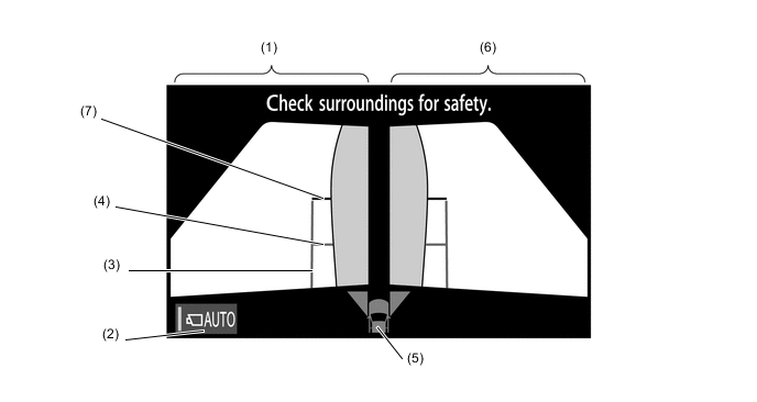
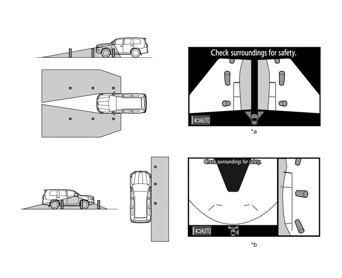
Wide Front View and Panoramic Mode
-
The wide front view and panoramic mode displays the vehicle front and an overhead image ofthe vehicle.
-
In the wide front view and panoramic mode, the screen displays as shown in the illustrationbelow:
Item Description (1) Wide Front View An image captured by the front television camera assembly of the area in front of the vehicle. (2) Panoramic View Displays an overhead image created by combining images from the front, rear, left and right side television camera assemblies. (3) Masking Since the driver's sense of the distance in front of the vehicle differs from actual conditions, masking is used. (4) Automatic Display Mode Selection Button Can be used to turn the automatic display mode on and off. When the automatic display mode is on, an indicator inside the button illuminates. (5) Camera Direction Display Vehicle Icon Indicates that the "wide front view" is displayed on the left side of the screen. (6) Display Mode Switch Button Pressing this button changes the display mode. (7) Forward Estimated Course Line*1 (When more than 90 °)
-
Displays the estimated course calculated from the steering angle.
-
Displays the estimated course ahead of the front of the vehicle on the outside of the steering direction, and the estimated course ahead of the rear of the vehicle on the inside of the steering direction.
(8) Panoramic View Vehicle Icon*2 Displays the vehicle position in the panoramic view. (9) Toyota Parking Assist-sensor System Cooperative Display*3 When the Toyota parking assist-sensor system detects an obstacle, the obstacle detection direction and distance are displayed superimposed on the screen. (10) Front Vehicle Width Extension Line (Blue) These lines are vehicle width extension lines. The lines displayed are wider than the actual vehicle width. (11) Front Distance Guide Line (Blue) These lines are distance guide lines showing the distance forward from the edge of the front bumper. (Approximately 1.0 m (3.3 ft.)) *1: Displayed when the guide line display is set to "Estimated Course Line Display Mode" and the steering angle is not positioned straight ahead.
*2: The color of the panoramic view vehicle icon can be changed. For details refer to the Repair Manual.
*3: Models with Toyota parking assist-sensor system
-
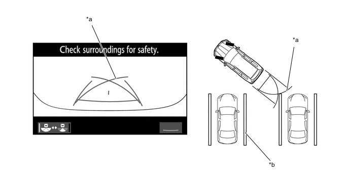
- a. Estimated Course Line Display Mode
-
The forward estimated course lines assist with driving operations performed to avoidobstacles by guiding the steering angle according to the estimated course on theoutside and inside of the steering direction to prevent overlapping of each guide linewith obstacles, etc.
*a Forward Estimated Course Line - - - b. Distance Guide Line Display Mode
-
Forward perpendicular parking operations are assisted by driving forward whilesteering so that the front distance guide lines and front vehicle width extension lines donot overlap the curb and actual white lines, etc.
-
Panoramic View and Rear View Mode
-
The panoramic view and rear view mode displays the vehicle rear and an overhead image of thevehicle.
-
In the panoramic view and rear view mode, the screen displays as shown in the illustrationbelow:
Item Description (1) Rear View An image captured by the rear television camera assembly of the area to the rear of the vehicle. (2) Panoramic View Displays an overhead image created by combining images from the front, rear, left and right side television camera assemblies. (3) Parking Assist Guide Line*1 (Blue) Indicates the path the vehicle will follow when the driver turns the steering wheel fully. (4) Rear Estimated Course Line*2 (Yellow) Moves in sync with the steering wheel to indicate the estimated reverse course of the vehicle. (5) Rear Vehicle Width Extension Line*3 (Blue) Indicates the estimated vehicle width. (6) Edge of Rear Bumper The edge of the rear bumper is displayed on the screen. (7) Camera Angle Mode Switch Button Switches the wide rear view. (8) Rear Distance Guide Line (Yellow/Red)*4 These lines are distance guide lines showing the distance from the edge of the rear bumper. (Approximately 1.0 m (3.3 ft.): yellow, approximately 0.5 m (1.6 ft.): red) (9) Rear Distance Guide Line (Blue)*5 These lines are distance guide lines showing the distance from the edge of the rear bumper. (Approximately 0.5 m (1.6 ft.)) (10) Display Mode Switch Button Pressing this button changes the display mode. (11) Panoramic View Vehicle Icon*6 Displays the vehicle position in the panoramic view. (12) Side Estimated Course Line*4 (Yellow)
-
Displays the estimated course calculated from the steering angle.
Displays the estimated course on the outside of the steering direction.
(13) Parking Assist-sensor SystemCooperative Display*7 When the Toyota parking assist-sensor system detects anobstacle, the obstacle detection direction and distance aredisplayed superimposed on the screen. (14) Front Vehicle Width Extension Line (Blue) These lines are vehicle width extension lines. The lines displayed are wider than the actual vehicle width. (15) Front Distance Guide Line (Blue) These lines are distance guide lines showing the distance forward from the edge of the front bumper. (Approximately 1.0 m (3.3 ft.)) (16) Blind Spot Monitor SystemCooperative Display*8 When the blind spot monitor system detects an obstacle, the direction of the approaching vehicle is displayed on the screen. *1: The side estimated course line or rear estimated course line and the parking assist guide line cannot be displayed simultaneously.
*2: Displayed when the guide line display is set to "Estimated Course Line Display Mode".
*3: Not displayed when the steering angle is approximately straight ahead.
*4: Displayed when the guide line display is set to "Estimated Course Line Display Mode" and the steering angle is not positioned straight ahead.
*5: Turns red in "Parking Assist Guide Line Display Mode" and "Distance Guide Line Display Mode".
*6: The color of the panoramic view vehicle icon can be changed. For details, refer to the Repair Manual.
*7: Models with Toyota parking assist-sensor system
*8: Models with blind spot monitor system
-
- a. Estimated Course Line Display Mode (Perpendicular Parking)
-
The rear vehicle width extension lines can be used to determine whether the vehicle isparked straight in the parking space by confirming whether the parking space lines andrear vehicle width extension lines are crossed or parallel.
*a Rear Vehicle Width Extension Line *b Rear Estimated Course Line *c Parking Space Line *d Side Estimated Course Line - b. Estimated Course Line Display Mode (Parallel Parking)
-
The rear vehicle width extension lines can be used to determine whether the vehicle isparked straight in the desired parking position by confirming the status of the shoulderand parking space lines, etc., and rear vehicle width extension lines.
*a Rear Vehicle Width Extension Line *b Rear Estimated Course Line *c Shoulder and Parking Space Lines, etc. *d Side Estimated Course Line - c. Parking Assist Guide Line Display Mode (Perpendicular Parking)
-
The parking assist guide line can be used to determine whether the vehicle is parkedstraight in the parking space by confirming whether the parking space lines andparking assist guide line are crossed or parallel.
*a Parking Assist Guide Line *b Parking Space Line - d. Parking Assist Guide Line Display Mode (Parallel Parking)
-
The parking assist guide line can be used to determine whether the vehicle is parkedstraight in the desired parking position by confirming the status of the shoulder andparking space lines, etc., and parking assist guide line.
*a Parking Assist Guide Line *b Shoulder and Parking Space Lines, etc. -
Wide Rear View Mode
-
The wide rear view mode displays the rear of the vehicle.
-
The wide rear view mode is displayed when the camera angle mode switch button is pressedduring display of the panoramic view and rear view mode.
-
In the wide rear view mode, the screen displays as shown in the illustration below:
Item Description (1) Parking Assist Guide Line*1 (Blue) Indicates the path the vehicle will follow when the driver turns the steering wheel fully. (2) Rear Estimated Course Line*2 (Yellow) Moves in sync with the steering wheel to indicate the estimated reverse course of the vehicle. (3) Rear Vehicle Width Extension Line*3 (Blue) Indicates the estimated vehicle width. (4) Rear Distance Guide Line (Yellow/Red)*4 These lines are distance guide lines showing the distance from the edge of the rear bumper. (Approximately 1.0 m (3.3 ft.): yellow, approximately 0.5 m (1.6 ft.): red) (5) Rear Distance Guide Line (Blue*5) These lines are distance guide lines showing the distance from the edge of the rear bumper. (Approximately 0.5 m (1.6 ft.)) (6) Display Mode Switch Button Pressing this button changes the display mode. (7) Interruption Icon*6, *7 Displayed when the Toyota parking assist-sensor system*6 or RCTA function*7 detects an obstacle, another vehicle, etc. (8) Camera Angle Mode Switch Button Switches the rear view. *1: The rear estimated course line and the parking assist guide line cannot be displayed simultaneously.
*2: Displayed when the guide line display is set to "Estimated Course Line Display Mode".
*3: Turns red in "Parking Assist Guide Line Display Mode" and "Distance Guide Line Display Mode".
*4: Displayed when the guide line display is set to "Estimated Course Line Display Mode" and the steering angle is not positioned straight ahead.
*5: Not displayed when the steering angle is approximately straight ahead.
*6: Models with Toyota parking assist-sensor system
*7: Models with blind spot monitor system
- a. Estimated Course Line Display Mode (Perpendicular Parking)
-
The rear vehicle width extension lines can be used to determine whether the vehicle isparked straight in the parking space by confirming whether the parking space lines andrear vehicle width extension lines are crossed or parallel.
*a Rear Vehicle Width Extension Line *b Rear Estimated Course Line *c Parking Space Line - - - b. Estimated Course Line Display Mode (Parallel Parking)
-
The rear vehicle width extension lines can be used to determine whether the vehicle isparked straight in the desired parking position by confirming the status of the shoulderand parking space lines, etc., and rear vehicle width extension lines.
*a Rear Vehicle Width Extension Line *b Rear Estimated Course Line *c Shoulder and Parking Space Lines, etc. - - - c. Parking Assist Guide Line Display Mode (Perpendicular Parking)
-
The parking assist guide line can be used to determine whether the vehicle is parkedstraight in the parking space by confirming whether the parking space lines andparking assist guide line are crossed or parallel.
*a Parking Assist Guide Line *b Parking Space Line - d. Parking Assist Guide Line Display Mode (Parallel Parking)
-
The parking assist guide line can be used to determine whether the vehicle is parkedstraight in the desired parking position by confirming the status of the shoulder andparking space lines, etc., and parking assist guide line.
*a Parking Assist Guide Line *b Shoulder and Parking Space Lines, etc. - e. Distance Guide Line Display Mode
-
In this mode, only a distance guide line is displayed when the driver does not needother guide lines.
*a Rear Distance Guide Line *b Parking Space Line -
Side View and Front View Mode
-
When the outside rear view mirrors are retracted, the screen switches from the Wide Front Viewand Panoramic Mode to the side view and front view mode.
-
The side view and front view mode displays the front passenger side and front of the vehicle.
-
In the side view and front view mode, the screen displays as shown in the illustration below
Item Description (1) Wide Front View An image captured by the front television camera assembly of the area in front of the vehicle. (2) Side View (Right Side) An image of the area to the right of the vehicle captured by the side television camera assembly RH. (3) Interruption Icon* When the Toyota parking assist-sensor system detects an obstacle, the obstacle detection direction and distance are displayed superimposed on the screen. (4) Rear Tire Contact Line (Blue) A guide line showing the rear right tire contact position. (5) Vehicle Width Parallel Line (Blue) A vehicle width guide line including the outer rear view mirror assembly. (6) Front Tire Contact Line (Blue) A guide line showing the front right tire contact position. (7) Front Distance Guide Line (Red) This line is distance guide line showing the distance forward from the edge of the front bumper. (Approximately 0.5 m (1.6 ft.)) (8) Automatic Display Mode Selection Button Can be used to turn the automatic display mode on and off. When the automatic display mode is on, an indicator inside the button illuminates. (9) Camera Direction Display Vehicle Icon Indicates that the "wide front view" is displayed on the left side of the screen. *: Models with Toyota parking assist-sensor system
-
Side View and Rear View Mode
-
When the outside rear view mirrors are retracted, the screen switches from the panoramic viewand rear view mode to the side view and rear view mode.
-
The side view and rear view mode displays the front passenger side and rear of the vehicle.
-
In the side view and rear view mode, the screen displays as shown in the illustration below:
Item Description (1) Rear View An image captured by the rear television camera assembly of the area to the rear of the vehicle. (2) Side View (Right Side) An image of the area to the right of the vehicle captured by the side television camera assembly RH. (3) Interruption Icon*1, *2 Displayed when the Toyota parking assist-sensor system*1or RCTA function*2 detects an obstacle, another vehicle,etc. (4) Rear Tire Contact Line (Blue) A guide line showing the rear right tire contact position. (5) Vehicle Width Parallel Line (Blue) A vehicle width guide line including the outer rear view mirror assembly. (6) Front Tire Contact Line (Blue) A guide line showing the front right tire contact position. (7) Front Distance Guide Line (Red) This line is distance guide line showing the distance forward from the edge of the front bumper. (Approximately 0.5 m (1.6 ft.)) (8) Display Mode Switch Button Pressing this button changes the display mode. (9) Camera Angle Mode Switch Button Switches the rear view. (10) Camera Direction DisplayVehicle Icon Indicates that the "rear view" is displayed on the left side ofthe screen. *1: Models with Toyota parking assist-sensor system
*2: Models with blind spot monitor system
-
-
-
-
PRECAUTIONS
-
General Precautions
-
Do not rely solely upon the multi-terrain monitor system. As with unequipped models, drive carefullywhile directly confirming the safety of your surroundings.
-
When driving, directly confirm the safety of your surroundings. Do not drive while only viewing themonitor screen.
-
The image displayed on the monitor screen may differ from actual conditions. Also, since the areacaptured by each television camera is limited, do not drive straight, make left and right turns oroperate the vehicle in reverse while only viewing the monitor screen. Doing so can lead tounforeseen accidents, such as collisions with other vehicles, etc. Always drive carefully while directlyconfirming the safety of your surroundings with the inner rear view mirror assembly, outer rear viewmirror assembly, etc.
-
The position of the guidelines displayed on the monitor screen may differ according to the number ofpassengers and load capacity. Always check the rear and drive while directly confirming the safety ofyour surroundings.
-
Use the multi-terrain monitor system with all the doors closed.
-
When the road surface is slick (frozen or covered with snow), do not use the panoramic viewmonitor system while using snow chains and driving on slopes. Doing so can lead to unforeseenaccidents such as collisions with other vehicles, etc.
-
These are just some of the operation procedures for each mode of the multi-terrain monitor system.The steering wheel timing and amount the steering wheel should be turned differ depending on theroad condition, road surface and vehicle condition when parking. Use the multi-terrain system withfull understanding of the above conditions. Always confirm that there is appropriate space beforeattempting to park the vehicle and operate the system.
-
-
Precautions For Panoramic View Mode Screen Display
-
The panoramic view is an image created by combining images from the front, rear, left and rightside television camera assemblies. Since the possible display area and display contents are limited,use the panoramic view monitor with full understanding of the panoramic view characteristics.
-
Since the vehicle icon displayed in the panoramic view is displayed using computer graphics, thevehicle color, shape and size may differ from the actual vehicle.
-
The clearness of the image at the four corners may be reduced, but this is not a malfunction.
-
The panoramic view may appear lighter or darker according to the lighting intensity near eachtelevision camera assembly.
-
The guidelines shown in the image could be deviated when the vehicle height is other than N(vehicles equipped with a vehicle height adjustment function).
-
The panoramic view does not anything above each television camera assembly installation positionand imaging range.
*a Imaging Range (Reference) *b Panoramic View -
There are blind spots near the vehicle that cannot be displayed on the panoramic view.
*a Blind Spot Area not Displayed on Screen *b Panoramic View -
Objects displayed on the wide front view and rear view may not be displayed on the panoramic view.
*a Panoramic View - - -
The panoramic view may display objects such as people and obstacles in a way that may differ from actual conditions.
*a Panoramic View - - -
If the back door with installed rear television camera assembly and front door with installed sidetelevision camera assembly (built into the outer rear view mirror assembly) are open, the panoramicview may not correctly display.
-
-
Precauttions For Under Vehicle Terrain View Mode Screen Display
-
The tire position guide lines and vehicle shape guide lines may differ from actual vehicle positionsdepending on the number of passengers, cargo weight, road grade, road surface conditions,brightness of the surrounding environment, etc. Always drive while directly confirming the safety ofyour surroundings.
-
The images displayed were previously captured. Therefore, the under vehicle terrain view may differfrom actual conditions in the following situations.
-
Obstacles enter the display range after the image is captured.
-
Sand, snow, etc. is driven through by the vehicle.
-
An obstacle has moved.
-
Water or mud is flowing within the display range.
-
When the vehicle is moved significantly such as slip.
-
The tire position guide lines and vehicle shape guide lines may differ from actual vehicle shape in thefollowing situations.
-
The tires are changed.
-
Optional equipment is installed.
-
-
Precautions For Television Camera Assembly Image
-
Do not subject the television camera assemblies to impacts. The multi-terrain monitor system maystop operating normally.
-
Since each television camera assembly is equipped with a special lens, the distance displayed on themonitor differs from actual conditions.
-
Since the lens of the front television camera assembly is made of glass, the lens can be damaged byflying rocks and other debris in the same way as windshield glass.
-
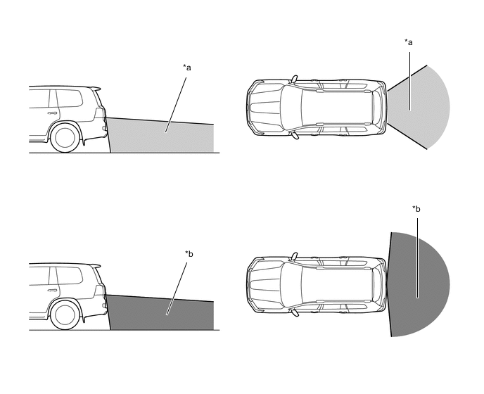
The area covered by the front television camera assembly is limited. The front television cameraassembly does not show objects close to either corner of the bumper or under the bumper.
-
The area covered by the rear television camera assembly is limited. The rear television cameraassembly does not show objects close to either corner of the bumper or under the bumper.
*a Panoramic View and Rear View *b Wide Rear View -
There are limits to the imaging range of the side television camera assemblies.
*a Panoramic View *b Side View and Wide Front View -
When the outside air temperature is low, the screen may become darker or appear faint. Sincemoving objects in particular may become distorted or disappear, always drive carefully while directlyconfirming the safety of your surroundings.
-
When light from the sun or headlights directly strikes the lens, the vehicle is in a dark location (atnight, etc.), or the temperature near the lens is high or low, the screen may become difficult to see,but this is not a malfunction.
-
When washing the vehicle, do not aim a high pressure washer nozzle directly at or around thetelevision camera assemblies. The television camera assembly may malfunction due to the highwater pressure.
-
Do not disassemble or modify the television camera assemblies as they use a waterproofconstruction. Water leakage may occur or the assemblies may operate incorrectly.
-
If the television camera assemblies are subject to sudden temperature changes, the system maystop operating normally.
-
If an organic solvent, wax, oil film remover, glass coating, etc., is present on a television cameraassembly lens, immediately wipe off with a soft cloth and wash with water.
-
If a television camera assembly lens is dirty, the camera cannot capture clear images. If water,snow, dirt or other foreign matter is present, wash with water and wipe with a soft cloth. Also, ifextremely dirty, wash with a mild detergent.
-
Do not strongly rub the television camera assembly lenses. The lens may become damaged andunable to capture clear images.
-
When under halogen, sodium and mercury lights, etc., the lights themselves and areas illuminatedby the lights may appear to fade in and out, resulting in a "flicker effect".
-
-
Road Condition Precautions
-
Depending on the number of occupants, the load conditions, the slope of the road, and bumps in theroad, a disparity may occur between the display indication and the actual distance on the roadsurface. Operate the vehicle carefully.
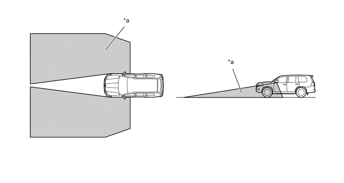
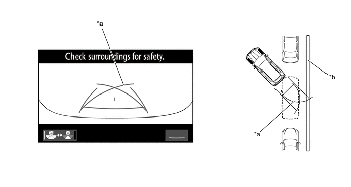
*a Steep Uphill Incline behind Vehicle *b Disparity *c Steep Downhill Incline behind Vehicle *d Vehicle Posture Changed by Passengers and Load -
If a steep uphill incline is behind the vehicle, an obstacle appears to be further away than it actuallyis, as shown in the illustration below.
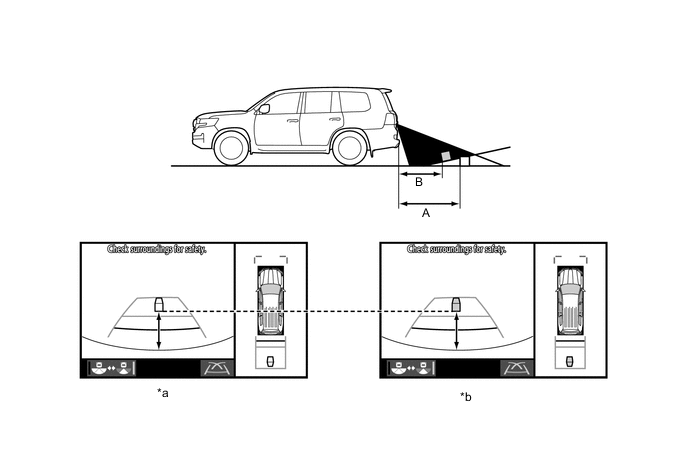
*a Screen Image in Case A *b Screen Image in Case B
-
-
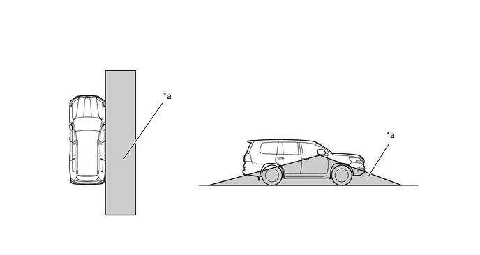
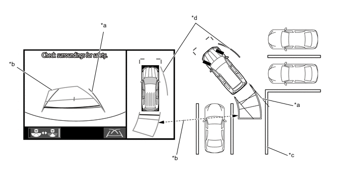
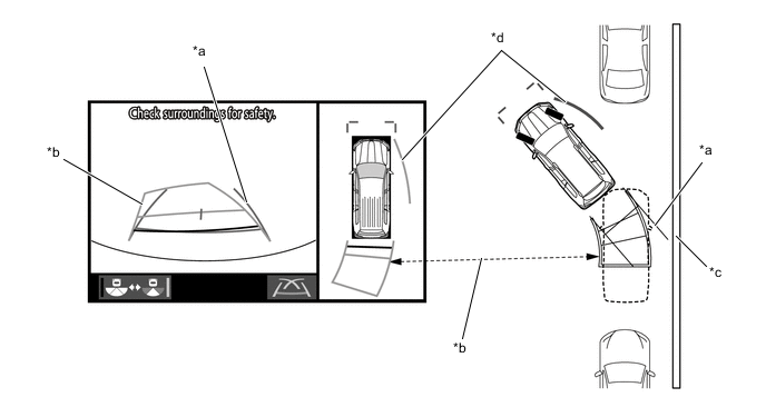
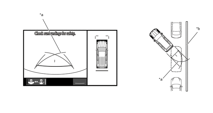
Precautions For 3-Dimensional Obstacles
-
Drive carefully when any 3-dimensional objects such as walls or vehicles are behind the vehicle asthe distance and estimated guide lines are provided based on the road surface.
-
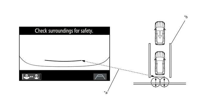
When passing close to a 3-dimensional object, the vehicle may come into contact with the objecteven if the estimated vehicle path seems not to be in contact with it on the screen.
-
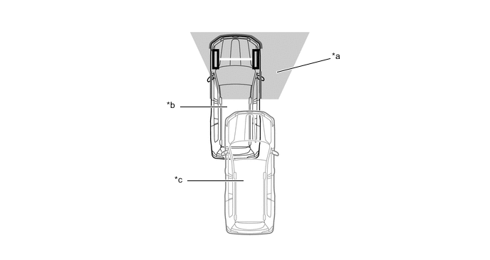
The distance indication as shown on the screen varies between 3-dimensional objects such as avehicle and objects on a flat plane such as the road surface. As shown in the following illustration,points A and B are actually vertically in the same position and point C is a short distance away fromthem: however, the points are displayed in order of distance from the vehicle, B, C and A.Therefore, the vehicle will come into contact with the 3-dimensional object if it is backed up to pointB on the screen.
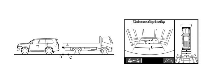
-
On slippery roads such as snowy roads, the estimated vehicle path and actual vehicle path may notmatch.
-
When only one parking line is provided, the vehicle may seem to be parallel to the line on the screeneven if it is not actually parallel.
-
-
-
DIAGNOSIS
-
The multi-terrain monitor system is equipped with a diagnosis function which can display the servicemenus. The method for entering the service menu screen is the same as the method used for themulti display. For details, refer to the Repair Manual.
-