NEW FEATURES
-
DESCRIPTION
-
General
-
The Lane Departure Alert (LDA) system is used depending on models.
-
The LDA system uses a forward recognition camera to detect lane markers on the road surface, assists the driver's steering operation by using the warning buzzer, and activates the lane departure warning when needed.
-
The LDA system also operates on roads with only one lane marker.
-
The LDA system is controlled by the forward recognition camera.
-
This system has a last memory function which memorizes the state of the LDA switch just before the engine switch is turned off and resumes the previous state when the engine switch is turned on (IG) again.
-
-
Precaution of Lane Departure Alert System
-
General Headline Precautions
-
Use the LDA system with clear lane markers.
-
The LDA system uses a forward recognition camera installed on the front of the vehicle to recognize white lines. The LDA system does not operate when white lines cannot be recognized. Also, since unnecessary warning sounds may be produced when white lines are not properly recognized, make sure to drive appropriately using the steering wheel even when using the LDA system.
-
Keep the windshield glass clean around the area where the forward recognition camera is mounted. The performance of forward recognition camera may be affected if dirt, raindrops, condensation, or snow is on the windshield glass.
-
Do not attach stickers or labels, nor affix any ornaments to the windshield glass.
-
Do not touch the lens of the forward recognition camera. Fingerprints left on the lens may cause inaccurate detection or non-detection and lane markers may not be detected accurately.
-
Do not remove the forward recognition camera. Since the angle of the forward recognition camera is precisely adjusted, angle adjustment must be performed after the forward recognition camera is reinstalled, otherwise the forward recognition camera may not recognize lane markers properly.
-
Do not subject the forward recognition camera to strong impacts.
-
When the system detects a malfunction, the buzzer sounds, "Lane Departure Alert Malfunction Visit Your Dealer" appears on the multi-information display, and the LDA system stops operating.
-
Since this does not affect normal driving, keep driving carefully.
-
The LDA system resumes by turning on the LDA main switch or turning from off to on the engine switch while the system is operating normally.
-
Changing tires or changing suspension parts may lead to a decline in performance of the system.
-
Depending on road surface conditions, it may be difficult to hear the warning sound.
-
Do not modify the headlights or attach stickers to the surface of the light.
-
Do not install or place anything on the hood or the grille. Also, do not install a grille guard (bull bars, kangaroo bar etc.).
-
If the windshield is fogged up, use the windshield defogger to remove fog from the windshield. When it is cold, using the heater with air blowing to the feet may cause the upper part of the windshield to fog up. This will have a negative effect on the images.
-
If the windshield needs to be replaced, contact your Toyota dealer or repair, or another duty qualified and equipped professional.
-
When the system detects a fault, the buzzer sounds and a warning message will appear to alert the driver and the system stops operating. However, normal driving can continue. Contact your Toyota dealer if any error alert is output repeatedly after turning the engine switch on (IG) again.
-
When zero point calibration has not been completed on Steering Sensor, LDA system doesn't work.
-
-
Precautions Concerning Road Conditions
-
If the system cannot recognize lane markers under the following conditions, the system will not operate.
-
When driving through an area with no lane markers, such as a tollbooth, a crossing or before a ticket checkpoint
-
When driving on a sharp curve
-
When lane markers are extremely narrow or extremely wide
-
When the vehicle leans to one side an unusual amount due to a heavy load or improper tire inflation pressure
-
When the following distance between your vehicle and the vehicle ahead is extremely short
-
When the lane markers are yellow (These may be more difficult for the system to recognize compared to white markers)
-
When the lane markers are Botts' dots (raised pavement markers), stone or indistinct
-
When the lane markers are on a curb etc.
-
When there are shadows on the road running parallel with lane markers, or if a shadow covers the lane markers
-
When driving on a particularly bright road surface, such as concrete
-
When driving on a road surface that is bright due to reflected light
-
When driving in a location where the light level changes rapidly, such as the entrance to or exit from a tunnel
-
When sunlight or the headlights of oncoming vehicles are shining directly into the camera lens
-
When driving on roads that are branching or merging
-
When driving on a road surface that is wet due to rain, previous rainfall, standing water, etc.
-
When the vehicle experiences strong up-and-down motion such as when driving on an extremely rough road or on a seam in the pavement
-
When headlight brightness at nighttime is reduced due to dirt on the lenses, or when the headlights are misaligned
-
When driving on winding roads or roads that are uneven
-
When driving on rough or unpaved roads
-
If the distance between vehicles is extremely short, lane markers may not be recognized correctly. Maintain an appropriate distance from the vehicle ahead.
-
When the vehicle is parked during hot weather, the system will not operate for a while after the engine switch is turned to on. When the temperature in the cabin reaches the appropriate level at which the forward recognition camera can operate, the system can be resumed.
-
-
-
-
SYSTEM DIAGRAM
-
LAYOUT OF MAIN COMPONENTS
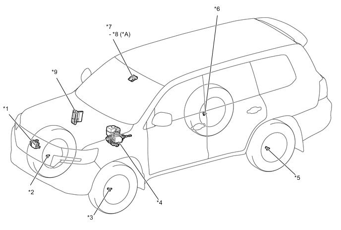
*A Models with Camera Heater (Forward Recognition Hood with Heater Sub-assembly) - - *1 Millimeter Wave Radar Sensor Assembly *2 Front Speed Sensor RH *3 Front Speed Sensor LH *4 Skid Control ECU *5 Rear Speed Sensor LH *6 Rear Speed Sensor RH *7 Forward Recognition Camera (Camera Sensor) *8 Camera Heater (Forward Recognition Hood with Heater Sub-assembly) *9 ECM - - 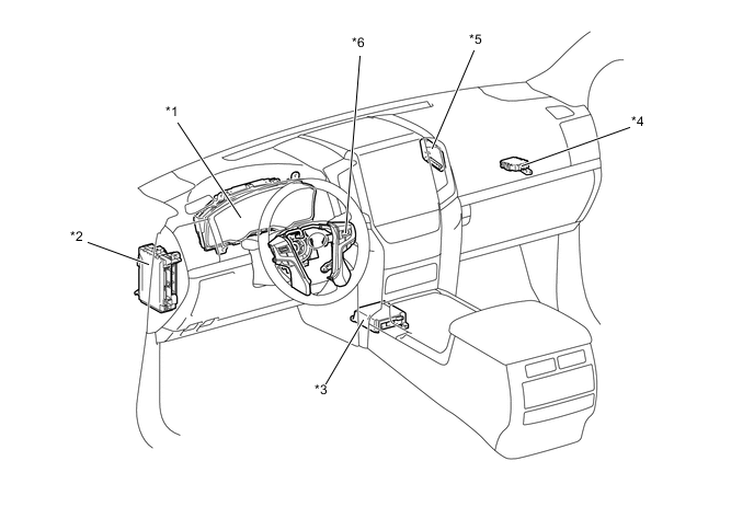
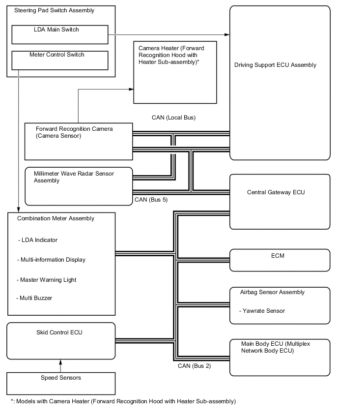
*1 Combination Meter Assembly *2 Main Body ECU (Multiplex Network Body ECU) *3 Airbag Sensor Assembly *4 Central Gateway ECU *5 Driving Support ECU Assembly *6 Steering Pad Switch Assembly -
FUNCTION OF MAIN COMPONENTS
Component Function Combination Meter Assembly LDA Indicator Illuminates or turns off in accordance with signals from the forward recognition camera. Multi-information Display Displays a warning message and white line to inform or warn the driver of the system condition in accordance with signals from the forward recognition camera. Master Warning Light Illuminates to warn the driver in accordance with signals from the forward recognition camera. Multi Buzzer Sounds to warn the driver in accordance with signals from the forward recognition camera. Forward Recognition Camera
-
Captures the road view ahead of the vehicle and detects lane markers on the driving lane, and calculates the radius to the center of the lane, lane width, distance from markers and heading angle deviation.
-
Controls the lane departure alert system.
-
Transmits the indicator illumination request signal, multi-information display indication request signal, and buzzer sound request signal to the combination meter assembly.
-
Receives vehicle information and turn signal light operation signals and sends a steering force signal to the power steering ECU assembly.
Camera Heater (Forward Recognition Hood with Heater Sub-assembly)* Heats the sheet heater in accordance with the signals from the forward recognition camera. Millimeter Wave Radar Sensor Assembly Transmits the forward vehicle information to the forward recognition camera. Driving Support ECU Assembly Transmits the LDA main switch signal to the forward recognition camera. ECM Transmits the reverse signal to the forward recognition camera. Skid Control ECU Sends a vehicle speed signal from the speed sensor to the forward recognition camera. Steering Pad Switch Assembly LDA Main Switch Detects an on/off status of the system and transmits a signal to the forward recognition camera. Meter Control Switch The multi-information display is operated using the meter control switches. Airbag Sensor Assembly Yawrate Sensor Detects yaw rate and transmits a signal to the forward recognition camera. Main Body ECU (Multiplex Network Body ECU) Sends country specification information signals to the forward recognition camera. Tech Tips
*: Models with Camera Heater (Forward Recognition Hood with Heater Sub-assembly)
-
-
CONSTRUCTION AND OPERATION
-
Operating Condition
Operating Conditions of LDA System Operation Condition Operating/Resume The lane departure warning function is activated when all of the following conditions are met:
-
The LDA main switch is on. (When the LDA main switch is pressed to turn on the LDA system, the LDA indicator illuminates.)
-
The vehicle speed is above approximately 50 km/h (32 mph) or more.
-
Lane markers are detected.
-
No turn signal command is detected.
-
System malfunction is not detected.
Suspended The lane departure alert system is suspended when any one of the following conditions is met:
-
The vehicle speed is not below approximately 50 km/h (32 mph) or more.
-
A turn signal command is detected.
-
No lane markers are detected.
-
Immediately after the lane departure warning is activated.
-
The airbag ECU assembly or speed sensors are malfunctioning.
-
A malfunction is detected in the LDA system.
-
The temperature of the forward recognition camera is abnormal.
-
The vehicle crosses halfway or further over a lane marker.
Canceled The lane departure alert system is stopped when any one of the following conditions is met:
-
The LDA main switch is off.
-
The LDA system is malfunctioning.
-
The engine switch is turned off.
The lane departure alert system resumes when the following conditions are met:
-
The conditions to start operation listed above returns to are satisfied.
-
The LDA system condition returns to normal.
-
The engine switch is turned off and on (IG) again to ensure normal operation, after the LDA system has been stopped by a system malfunction.
Operating Conditions of LDA System (Vehicle Sway Warning) Operation Condition Operating/Resume The lane departure warning function is activated when all of the following conditions are met:
-
The vehicle sway warning function has been turned on using the customize setting.
-
The vehicle speed is above approximately 50 km/h (32 mph) or more.
-
Lane markers are detected.
-
System malfunction is not detected.
Suspended The lane departure alert system is suspended when any one of the following conditions is met:
-
The vehicle speed is below approximately 50 km/h (32 mph) or more.
-
A turn signal command is detected.
-
No lane markers are detected.
-
Immediately after the lane departure warning is activated.
Canceled The lane departure alert system is stopped when any one of the following conditions is met:
-
The LDA system is malfunctioning.
-
Engine switch is turned off.
-
The vehicle sway warning function is turned off using the customize setting.
The lane departure alert system resumes when the following conditions are met:
-
The conditions to start operation listed above returns to are satisfied.
-
The LDA system condition returns to normal.
-
The engine switch is turned off and on (IG) again to ensure normal operation, after the LDA system has been stopped by a system malfunction.
-
-
System Control
-
Function Overview (Lane Departure Alert Function)
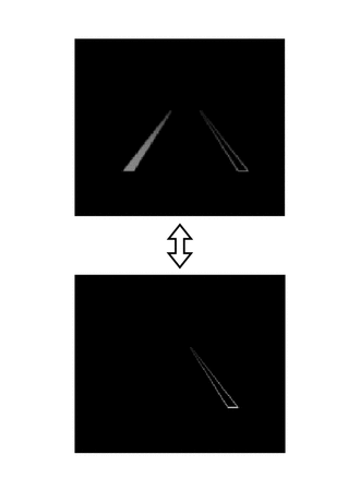
If the system judges that the vehicle may deviate from the lane it is in, the system blinks the lane maker in the multi-information display and sounds a buzzer so that the driver can take action to avoid lane departure.
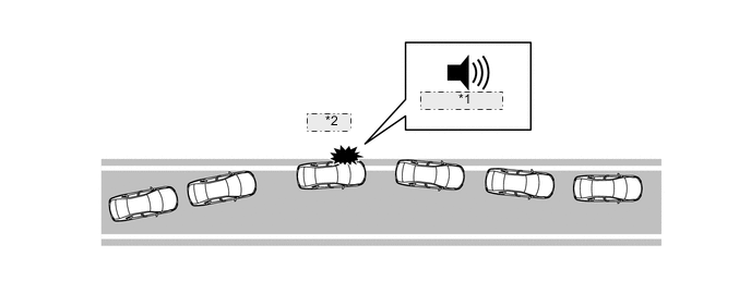
*1 Buzzer Sounds *2 Warning -
Function Overview (Vehicle Sway Warning Function)
The system detects drift of the vehicle within its lane, which is often the result of a driver who is tired, distracted or not looking ahead, based on the position of the vehicle within its lane and the steering inputs of the driver, and alerts the driver before a lane departure or collision occurs.
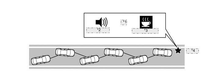
*1 and *2 Buzzer Sounds *3 Warning Display *4 Warning
-
-
Function
-
Steering Pad Switch
Using the meter control switches of the steering pad switch assembly, the steering assist functions and the unsteady driving alert functions can be customized.
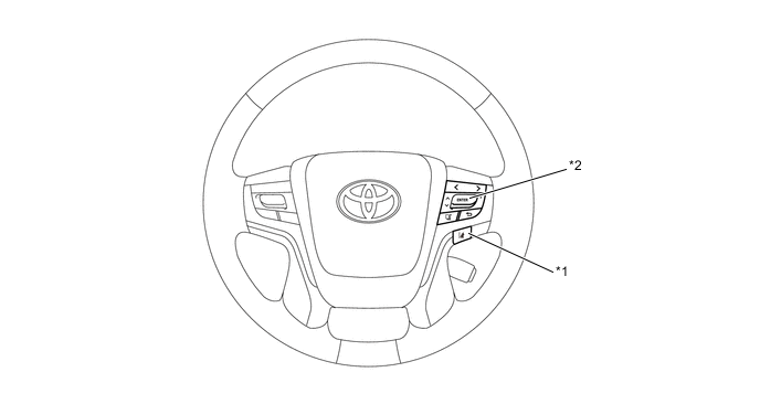
*1 LDA Main Switch *2 Meter Control Switches Customize Lane Departure Alert Functions Item (Select using the up/down button of the meter control switch) Description Setting (Change using the center button of the meter control switch) Warning Sensitivity Timing of lane departure warning
-
Normal
-
High
Customize Vehicle Sway Warning Functions Item (Select using the up/down button of the meter control switch) Description Setting (Change using the center button of the meter control switch) Vehicle Sway Warning Vehicle sway warning function
-
ON
-
OFF
Warning Sensitivity Vehicle Sway Warning sensitivity
-
High
-
Standard
-
Low
-
-
Forward Recognition Camera
-
The forward recognition camera captures the road image up to approximately 50 m (164 ft.) ahead of the forward recognition camera.
-
The forward recognition camera detects lane markers and calculates the radius to the center of the lane, heading angle deviation, lateral deviation from the center of the lane, and the lane width.
Tech Tips
When one of the following operations is conducted, the forward recognition camera angle must be adjusted. For details, refer to the Repair Manual.
-
The forward recognition camera is removed and reinstalled or replaced.
-
Parts relating to the tire or suspension are replaced or adjusted.
-
Strong force is applied onto the forward recognition camera.
-
-
The lane departure alert system does not operate if the vehicle approaches the lane marker (but does not cross it), as long as the vehicle remains parallel with the lane marker.
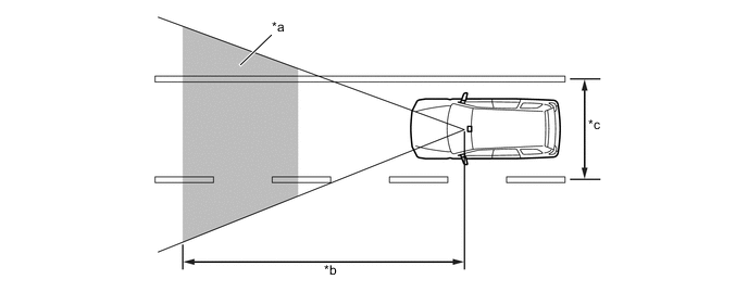
*a Image Processing Range *b Approximately. 50 m (164 ft.) *c Forward Recognition Camera captures the image of approximately 3.0 m (9.8 ft.) or more. - - Figure 1. Forward Recognition Camera Calculation
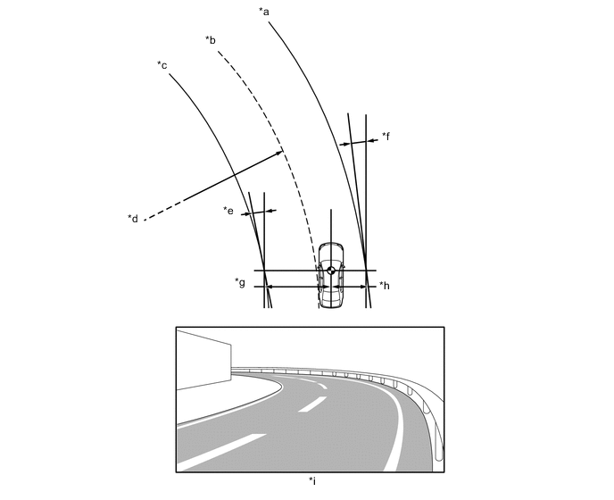
*a Right Lane Marker *b Center of Lane *c Left Lane Marker *d Lane Radius (If only the left line marker or right lane marker is recognized, the radius of the recognized lane marker will be calculated.) *e Angle between the vehicle traveling direction and left lane marker. *f Angle between the vehicle traveling direction and right lane marker. *g Distance from the vehicle to left lane marker. *h Distance from the vehicle to right lane marker. *i Image Captured by Forward Recognition Camera - -
-
-
Millimeter Wave Radar Sensor Assembly
-
The millimeter wave radar sensor assembly consists of a millimeter wave radar circuit, signal processing circuit and CPU.
-
The millimeter wave radar outputs waves when the vehicle speed is above 0 km/h (0 mph), and not when the vehicle speed is at 0 km/h (0 mph).* The millimeter wave radar uses frequencies in the 76 GHz band.
-
The receiving antennas receive the millimeter waves that have been reflected.
-
The signal processing circuit detects the distance, relative speed, and the direction of the object by generating millimeter waves and calculating the signals received by the receiving antennas. Then, it transmits this information to the driving support ECU assembly.
-
*: The setting with which electric waves stop while the vehicle is stopped differs depending on the destinations.
-
-
-
-
OPERATION
-
Combination Meter Assembly
-
The combination meter assembly illuminates the indicator lights or displays an indicator on the multi-information display, and sounds a buzzer (which is built into the combination meter assembly) in accordance with the respective condition.
-
Examples are shown below for the illumination or display of each indicator, warning light or multi-information display.
Lane Departure Alert System ON [Approximately 50 km/h (32 mph) or more] Condition Multi-information Display LDA Indicator Buzzer Lane Markers Detected 
Illuminates - One Lane Marker Detected 
Illuminates - Lane Markers Not Detected 
Illuminates -
-
Lane Markers Detected
-
Lane Departure Alert Operating
Illuminates Sounds The lane marker icons blink (Amber) Warning Message Condition Multi-information Display Master Warning Light Buzzer Windshield Glass is Dirty. Forward Camera
Systems
Unavailable
Clean Windshield
- Sounds System Malfunction Lane Departure
Alert
Malfunction
Visit You Dealer
- Sounds Temperature of Forward Recognition Camera is Abnormal. Forward Camera
System
Unavailable
- Sounds LDA main switch is turned on at approximately 50 km/h (32 mph) or lower Lane Departure
Alert
Unavailable
Below Approx.
32 mph
- - Vehicle decelerates to below operating
-
Displayed once after the engine switch is turned on (IG)
When the millimeter wave radar sensor cannot be used temporarily. Lane Departure Alert Unavailable - Sounds -
-
-
-
Diagnosis
-
If a malfunction is detected in the lane departure alert system the forward recognition camera cancels the lane departure alert system, turns on the LDA indicator umber and illuminates the master warning light, sounds the buzzer in the combination meter assembly, and displays a message on the multi-information display to inform the driver of the malfunction.
-
At the same time, the malfunction is stored in memory as a Diagnostic Trouble Code (DTC). For details, refer to the Repair Manual.
-