NEW FEATURES
-
DESCRIPTION
-
Some of the functions have been changed due to the change in the sensor.
-
The display has been changed due to the change in the combination meter assembly.
-
Some of the clearance sonar icon that are displayed on the interruption screen while each camera image is displayed have changed due to the addition of functions for the multi-terrain monitor system.*
-
*: Models with multi-terrain monitor system
-
-
When a sensor detects an obstacle with the shift lever not in P or R, the buzzer can be temporarily muted using the buzzer mute switch in the multi-display assembly.
-
-
DETECTION AREA
Figure 1. Corner Area
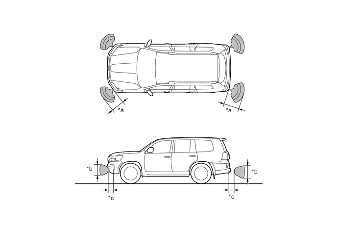
*a Approx. 60 cm (23.6 in.) *b Approx. 40 cm (15.8 in.) *c Approx. 20 cm (7.8 in.) - - Figure 2. Rear Center Area
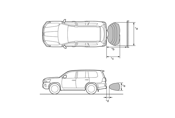
*a Approx.160 cm (63 in.) *b Approx.150 cm (59 in.) *c Approx. 100 cm (39.4 in.) *d Approx. 20 cm (7.8 in.) *e Approx. 50 cm (19.7 in.) - - Note
These detection ranges are applicable when positioning a 60mm (2.4 in.) diameter pole parallel or perpendicular to the ground. The ranges vary depending on the measuring method and type of obstacle.
-
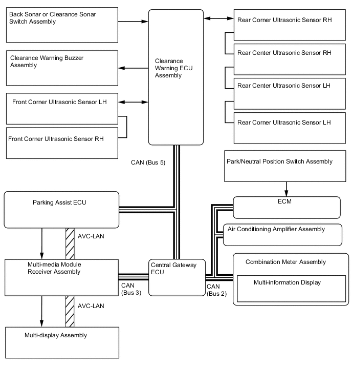
SYSTEM DIAGRAM
-
LAYOUT OF MAIN COMPONENTS
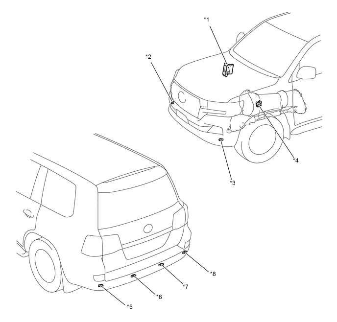
*1 ECM *2 Front Corner Ultrasonic Sensor RH *3 Front Corner Ultrasonic Sensor LH *4 Park/Neutral Position Switch Assembly *5 Rear Corner Ultrasonic Sensor LH *6 Rear Center Ultrasonic Sensor LH *7 Rear Center Ultrasonic Sensor RH *8 Rear Corner Ultrasonic Sensor RH 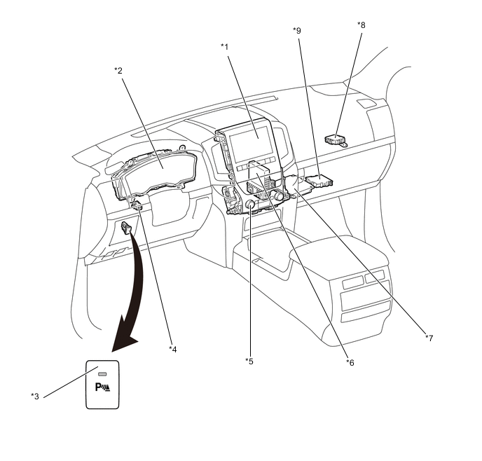
*1 Multi-display Assembly *2 Combination Meter Assembly *3 Back Sonar or Clearance Sonar Switch Assembly *4 Clearance Warning Buzzer Assembly *5 Multi-media Module Receiver Assembly *6 Air Conditioning Amplifier Assembly *7 Parking Assist ECU *8 Central Gateway ECU *9 Clearance Warning ECU Assembly - - -
ULTRASONIC SENSOR
-
The ultrasonic sensor consists of the microphone that transmits and receives ultrasonic wave and circuit portion.
Figure 3. Ultrasonic Sensor (Rear Corner LH and RH and Rear Center LH and RH)
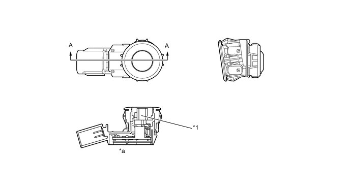
*1 Microphone - - *a A-A Cross Section - - Figure 4. Ultrasonic Sensor (Front Corner LH and RH)
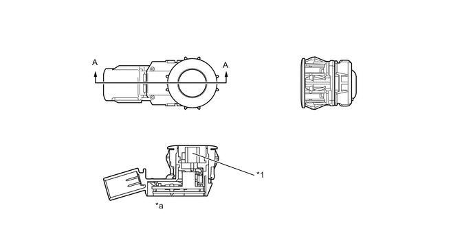
*1 Microphone - - *a A-A Cross Section - -
-
-
CLEARANCE WARNING BUZZER
-
Depending on the detection distance and the detection area, the sound pattern of the clearance warning buzzer will vary.
Detection Area Detection Distance cm (in.) Buzzer Sound Pattern ON/ OFF Time (msec.) Front Corner Long 60 +/- 6 to 45 +/- 5 (23.6 +/- 2.4 to 17.7 +/- 2.0) 200 / 200 Middle 45 +/- 5 to 35 +/- 4 (17.7 +/- 2.0 to 13.8 +/- 1.6) 100 / 100 Short 35 +/- 4 or less (13.8 +/- 1.6 or less) Continuous Sound / 0 Rear Corner Long 60 +/- 6 to 45 +/- 5 (23.6 +/- 2.4 to 17.7 +/- 2.0) 200 / 200 Middle 45 +/- 5 to 35 +/- 4 (17.7 +/- 2.0 to 13.8 +/- 1.6) 100 / 100 Short 35 +/- 4 or less (13.8 +/- 1.6 or less) Continuous Sound / 0 Rear Center Longest 150 +/- 15 to 80 +/- 8 (59.1 +/- 5.9 to 31.5 +/- 3.1) 500 / 200 Long 80 +/- 8 to 65 +/- 7 (31.5 +/- 3.1 to 25.6 +/- 2.8) 200 / 200 Middle 65 +/- 7 to 50 +/- 5 (25.6 +/- 2.8 to 19.7 +/- 2.0) 100 / 100 Short 50 +/- 5 or less (19.7 +/- 2.0 or less) Continuous Sound / 0
-
-
MULTI-INFORMATION DISPLAY
-
The location of an obstacle and the approximate distance between the vehicle and the obstacle are displayed on the multi-information display.
-
The number of lines shown on the display changes based on the actual distance and flashes when the distance is short.
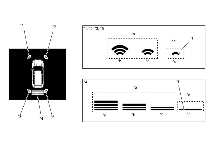
*1 Front Corner LH *2 Front Corner RH *3 Rear Corner LH *4 Rear Center *5 Rear Corner RH - - *a Yellow *b Long *c Middle *d Red *e Short *f Flashes *g Longest - - -
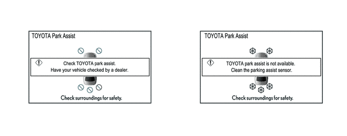
Screens displaying warning messages relating to an ultrasonic sensor malfunction, ultrasonic sensor freezing, or presence of foreign matter on the ultrasonic sensor are displayed on the multi-information display.
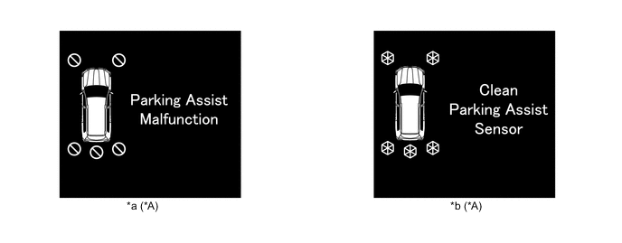
*A All sensor icons illuminate regardless of which sensor detected the malfunction, freezing or dirt. - - *a Malfunction Warning *b Frozen/Dirty Warning
-
-
MULTI DISPLAY
-
If an obstacle is detected when the multi-terrain monitor system is activated, the approximatedistance between the vehicle and the obstacle is displayed on the multi-display assembly.*
-
*: Models with multi-terrain monitor system
-
-
The distance is displayed by color based on the actual distance to the obstacle. When an obstacle is detected at the long or middle distance, the indicator is yellow. The color changes from yellow to red when the distance becomes short.
Figure 5. Side Simultaneous View, Front View and Side View, Wide Rear View
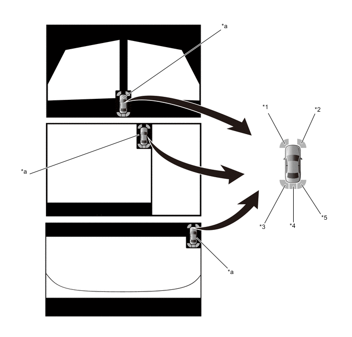
*1 Front Corner LH *2 Front Corner RH *3 Rear Corner LH *4 Rear Center *5 Rear Corner RH - - *a Clearance Sonar Icon - - Note
The illustration shown is an example only. The illustration may differ from the actual vehicle screen.
Figure 6. Wide Front View and Side Simultaneous View, Underfloor View and Side Simultaneous View, Wide Rear View and Side Simultaneous View
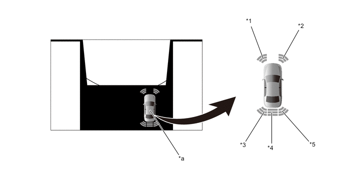
*1 Front Corner LH *2 Front Corner RH *3 Rear Corner LH *4 Rear Center *5 Rear Corner RH - - *a Clearance Sonar Icon - - Note
The illustration shown is an example only. The illustration may differ from the actual vehicle screen.
Figure 7. Panoramic View
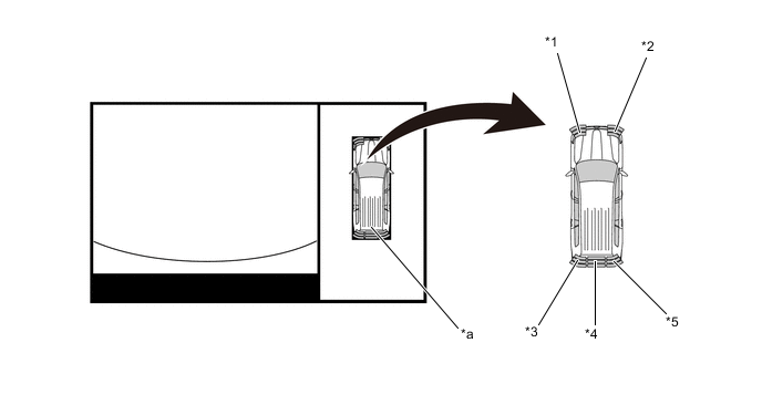
*1 Front Corner LH *2 Front Corner RH *3 Rear Corner LH *4 Rear Center *5 Rear Corner RH - - *a Clearance Sonar Icon - - Note
The illustration shown is an example only. The illustration may differ from the actual vehicle screen.
Figure 8. Warning Message
Note
The illustration shown is an example only. The illustration may differ from the actual vehicle screen.
-
When a sensor detects an obstacle with the shift lever not in P or R, the buzzer can be temporarily muted using the buzzer mute switch in the multi-display assembly.
-
The mute function is canceled if the vehicle speed reaches a certain level.
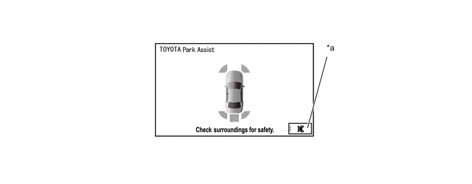
*a Buzzer Mute Switch - - Note
The illustration shown is an example only. The illustration may differ from the actual vehicle screen.
-
The display timing and detection distance on the multi-display can be customized.
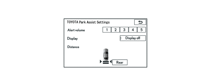
Note
The illustration shown is an example only. The illustration may differ from the actual vehicle screen.
-