NEW FEATURES
-
GENERAL
-
Outline
-
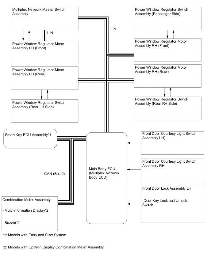
The power window control system controls power window operation using the power window regulator motors.
-
The main controls for this system are the multiplex network master switch assembly and the power window regulator switch assemblies. Operating a window switch results in electrical power being transmitted to the corresponding power window regulator motor.
-
-
Precaution
-
Ignition Switch Expressions
-
The type of ignition switch used on this model differs depending on the specifications of the vehicle. The expressions listed in the table below are used in this section.
Expressions Ignition Switch (Position) Engine Switch (Condition) Ignition Switch off LOCK Off (LOCK) Ignition Switch ACC ACC On (ACC) Ignition Switch ON ON On (IG) Engine Start START On (Start)
-
-
-
-
SYSTEM DIAGRAM
-
PARTS LOCATION
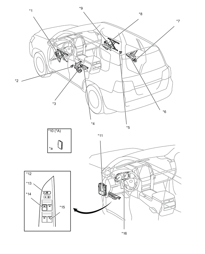
*A Models with Entry and Start System - - *1 Power Window Regulator Motor Assembly LH (Front) *2 Front Door Courtesy Light Switch Assembly LH *3 Power Window Regulator Motor Assembly LH (Rear) *4 Power Window Regulator Switch Assembly (Rear LH Side) *5 Front Door Courtesy Light Switch Assembly RH *6 Power Window Regulator Switch Assembly(Rear RH Side) *7 Power Window Regulator Motor Assembly RH (Rear) *8 Power Window Regulator Motor Assembly RH (Front) *9 Power Window Regulator Switch Assembly (Passenger Side) *10 Smart Key ECU Assembly *11 Main Body ECU (Multiplex Network Body ECU) *12 Multiplex Network Master Switch Assembly *13 Window Lock Switch *14 Power Window Regulator Switch Assembly (Driver) *15 Power Window Regulator Switch Illumination *16 Combination Meter Assembly *a Refer to the Service Bulletin for the installation position of the part. - - -
DETAILS
-
System Control
-
The power window control system has the following functions:
Function Outline Power Up-and-down (All Doors) This function causes the window to open or close while the multiplex network master switch assembly or power window regulator switch assembly is being pulled halfway up or pushed halfway down. The window stops as soon as the switch is released. One-touch AutoUp-and-down (AllDoors or Driver DoorOnly) The one-touch auto up-and-down function enables the window to be fully opened or closed by firmly operating the multiplex network master switch assembly or power window regulator switch assembly. Variable SpeedControl (All Doors orDriver Door Only) This control minimizes the occurrence of noise during the power window open/close operation by changing the operating speed of the power window regulator motor. Jam Protection (All Doors) The jam protection function automatically stops the power window and moves it downward if a foreign object gets jammed in the window during one-touch auto-up operation or power up operation. Catch Protection The catch protection function automatically stops the power window if an object gets caught by the door window glass during one-touch auto-down operation or power down. Remote Control (All Doors) The multiplex network master switch assembly can control the up-and-down operation of the windows. Window Lock
-
Operation of the 3 passenger windows is disabled when the window lock switch is on.
-
Similarly, the illumination of the power window regulator switches, except the one for the driver door, is turned off to inform the occupants that the windows cannot be operated.
Key Off Operation
-
Makes it possible to operate the power windows for approximately 43 seconds after the engine switch is turned off, if either front door is not opened.
-
If the driver door or front passenger door is opened during automatic window operation while the key-off operation function is on, the window will stop operating.
Key-linked Up-and-down When the driver door is locked, and the mechanical key in the driver door isturned and maintained in the lock direction for 1.5 seconds or more, main bodyECU (Multiplex Network Body ECU) activates the power window motors to raiseall door windows while the mechanical key is turned.
Similarly, when the driver door is unlocked, turning and maintaining the driverdoor key cylinder in the unlock direction for 1.5 seconds or more will cause alldoor windows to be lowered.
Transmitter-linked Up-and-down When the smart key ECU assembly*1 or door control transmitter assembly*2receives a lock or unlock signal from the transmitter for longer than 3 seconds, themain body ECU (Multiplex Network Body ECU) controls their power windowmotors in accordance with the signal to close or open the windows. Power Window GlassOpen Warning*3 When the engine switch is turned from on (IG) to off and the driver door is opened with the power window glass open, the buzzer in the combination meter assembly sounds once. Then, a warning message appears on the multi-information display and the master warning light blinks. *1: Models with entry and start system
*2: Models without entry and start system
*3: Models with optitron display combination meter assemblydels without entry and start system
Tech Tips
The ECU built into each power window motor stores the initial position of its door window glass.The initial position is not cleared even if the terminals, fuses or the power window motor connector aredisconnected. However, after removing or reinstalling window components, or replacing the powerwindow regulator switch assembly or power window regulator motor assembly, the stored initialposition data must be cleared and/or initialization must be performed.
For details, refer to the Repair Manual.
-
-
Variable Speed Control
-
Opening Power Window
-
To minimize noise when the power window down function starts operating, the power window regulator motor assembly increases the door window glass opening speed to normal speed when the front door window glass is between the fully closed position and an open position of approximately 80 mm (3.2 in.), and when the rear door window glass is between the fully closed position and an open position of approximately 90 mm (3.5 in.).Also, the assembly reduces the opening speed from normal speed when the front door window glass is between the fully opened position and an open position of approximately 140 mm (5.5 in.), and when the rear door window glass is between the fully opened position and an open position of approximately 135 mm (5.3 in.).
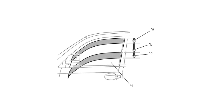
*1 Door Window Glass - - *a Acceleration Approx. 80 mm (3.2 in.) *b Normal Speed *c Deceleration Approx. 140 mm (5.5 in.) - - -
Closing Power Window
-
To minimize noise when the power window up function starts operating, the power window regulator motor assembly increases the door window glass closing speed to normal speed when the front door window glass and rear door window glass are between the fully opened position and an open position of approximately 25 mm (1 in.). Also, the assembly reduces the closing speed from normal speed when the front door window glass is between the fully closed position and an open position of approximately 70 mm (2.8 in.), and when the rear door window glass is between the fully closed position and an open position of approximately 90 mm (3.5 in.).
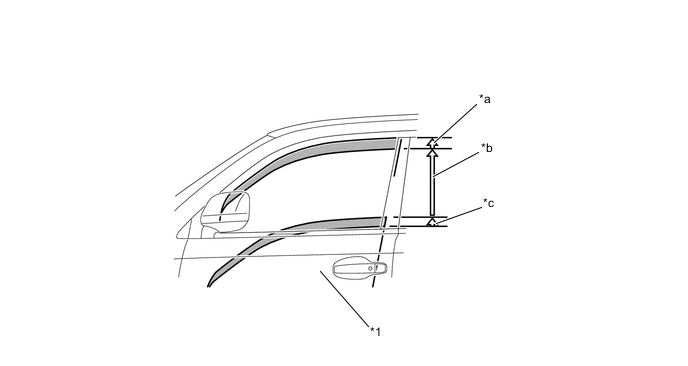
*1 Door Window Glass - - *a Deceleration Approx. 70 mm (2.8 in.) *b Normal Speed *c Acceleration Approx. 25 mm (1.0 in.) - -
-
-
Jam Protection Function
-
The jam protection function automatically stops the power window and moves it downward if an object gets jammed in the door window glass during one-touch auto up operation or power up operation.
-
The operation of the jam protection function is as described below.
Situation Operation During auto up operation Down operation until door window glass downward movement of 125 mm (4.93 in.) is reached, or 5 seconds elapse During manual up operation Down operation until door window glass downward movement of 30 mm (1.18 in.) is reached, or 5 seconds elapse Tech Tips
After the jam protection function has operated when an auto up or manual up operation was performed, the jam protection function will not operate if the manual up operation is performed again within approximately 4 seconds.
-
-
Catch Protection Function
-
A catch protection function automatically stops the power window if an object gets caught bythe door window glass during one-touch auto down operation and power down operation.
Tech Tips
After the catch protection function has operated when an auto down or manual down operation was performed, the catch protection function will not operate if the manual down operation is performed again within approximately 4 seconds.
-
-
Power Window Regulator Motor Assembly
-
The magnet and Hall IC in the power window motor are used in the power window jam protection function and catch protection function.
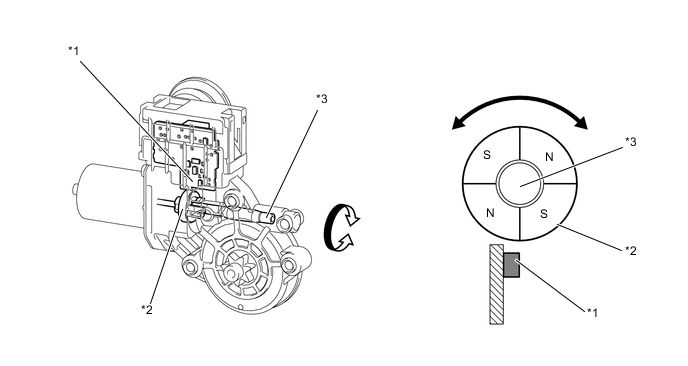
*1 Hall IC *2 Magnet *3 Worm Shaft - - -
The Hall IC converts the changes in magnetic flux that occur through the rotation of the magnetinto pulse signals and outputs them to the ECU built-into the power window motor.
-
To control the jam protection function and catch protection function, the ECU determines theamount of movement and determines if the window glass is jamming based on the pulse signalA from the Hall IC; The direction of the window glass movement is determined based on thephase difference between the pulses of Hall IC signals A and B.
Figure 1. Judgement of Movement and Jamming:
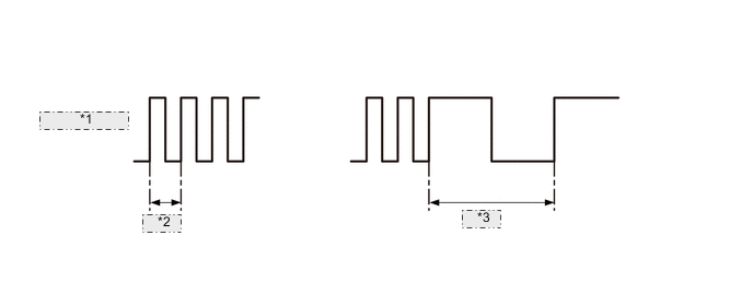
*1 Hall IC Signal *2 Normal *3 Jammed Figure 2. Judgement of Movement Direction:
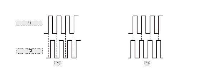
*1 HallIC Signal A *2 HallIC Signal B *3 DOWN *4 UP
-
-
-
Fail-safe
-
If the Hall IC in the power window motor malfunctions, some power window functions will beprohibited for fail-safe mode:
-
The power window operates when the power window switch is fully pushed down or pulled up and held in that position.
-
-
-
Diagnosis
-
If a power window ECU detects a malfunction in the power window control system, a Diagnostic Trouble Code (DTC) is stored in memory.
-
The DTCs can be read using the Global TechStream (GTS). For details, refer to the Repair Manual.
-
-
-