NEW FEATURES
-
COMBINATION METER
-
Description
-
The designs of the optitron display type combination meter assembly and the analog display type combination meter assembly have been changed.
-
A 4.2-inch color TFT type multi-information display has been adopted for the optitron display type combination meter assembly.
-
A pointer indication has been adopted for the speedometer, tachometer, fuel gauge, water temperature meter, voltage meter, and oil pressure meter of the optitron display type combination meter assembly.
-
A welcome performance function that delays the meter illumination has been adopted for the optitron display type combination meter assembly. In addition, dedicated opening animation has been adopted for the TFT type multi-information display.
-
Silver painted, hair-lined speedometer ring and tachometer ring have been adopted for the optitron display type combination meter assembly for sophisticated appearance.
-
A negative indication liquid crystal display has been adopted for the odometer/trip meter of the optitron display type combination meter assembly, providing a higher contrast appearance.
-
A meter ring integrated acrylic design dial has been adopted for the speedometer and tachometer of the optitron display type combination meter assembly, providing a touch of class.
-
An odometer/trip meter, a rheostat, a DPF, and a shift gear indicator have been provided in the liquid crystal odometer/trip meter display in the analog display type combination meter assembly.
-
A BOS indicator light, a parking brake indicator light, and a DPF indicator light have been added in the analog display type combination meter assembly.
-
A new dial plate with a back plate printed in turquoise blue has been adopted for the analog display type combination meter assembly to allow the user to switch the dial color in the night time by turning the illumination on or off (Turned on: Turquoise blue, Turned off: White).
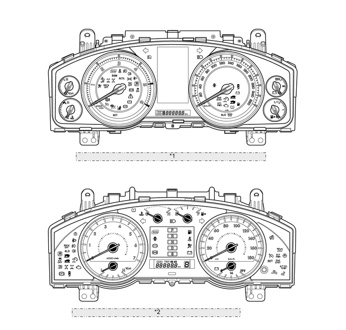
*1 Models with Optitron Display Type Combination Meter Assembly *2 Models with Analog Display Type Combination Meter Assembly
-
PRECAUTION
-
Ignition Switch Expressions
-
The type of ignition switch used on this model differs depending on the specifications of the vehicle. The expressions listed in the table below are used in this section.
Expressions Ignition Switch (Position) Engine Switch (Condition) Ignition Switch off LOCK Off (LOCK) Ignition Switch ACC ACC On (ACC) Ignition Switch ON ON On (IG) Engine Start START On (Start)
-
-
-
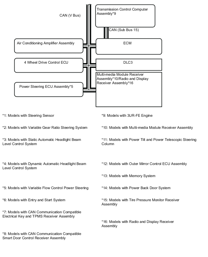
System Diagram
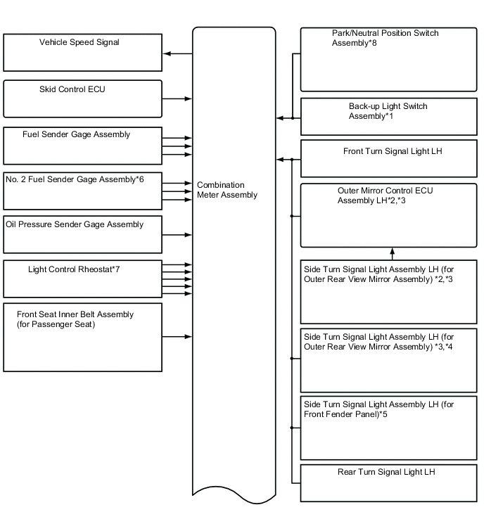
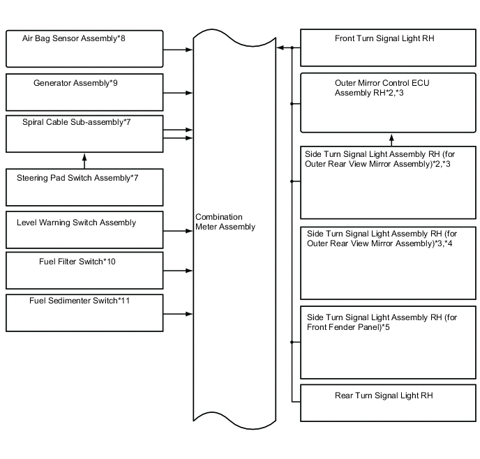
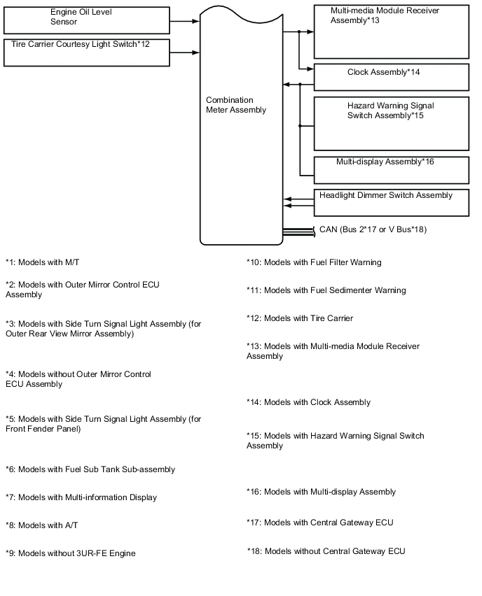
Figure 1. Models with Central Gateway ECU (Representative Example: LHD)
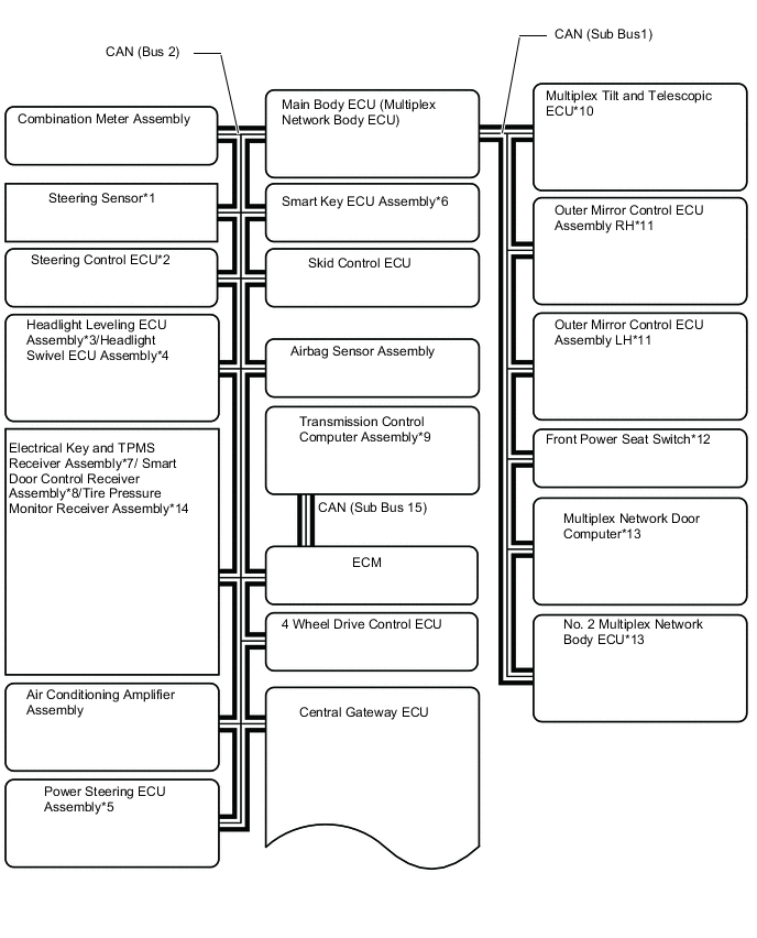
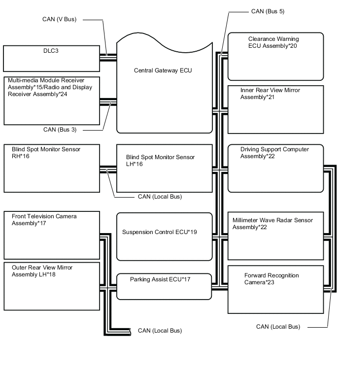
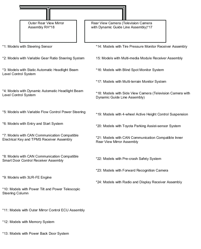
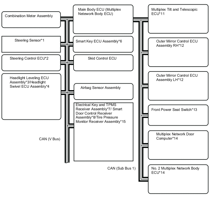
Figure 2. Models without Central Gateway ECU (Representative Example: LHD)
-
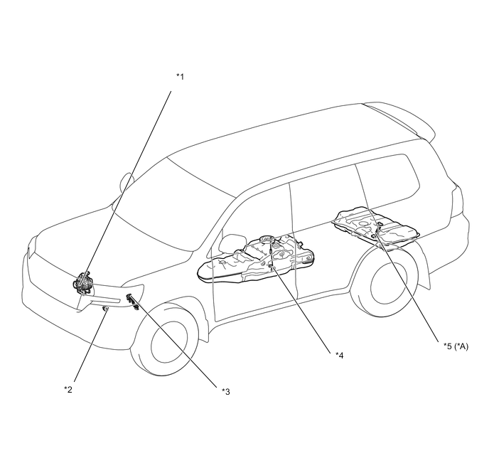
Layout of Main Components
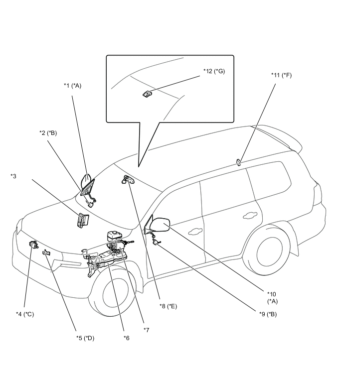
*A Models with Side View Camera (Television Camera with Dynamic Guide Line Assembly) *B Models with Outer Mirror Control ECU Assembly *C Models with Pre-crash Safety System *D Models with Multi-terrain Monitor System *E Models with CAN Communication Compatible Inner Rear View Mirror Assembly *F Models with CAN Communication Compatible Electrical Key and TPMS Receiver Assembly *G Models with Forward Recognition Camera - - *1 Outer Rear View Mirror Assembly RH *2 Outer Mirror Control ECU Assembly RH *3 ECM *4 Millimeter Wave Radar Sensor Assembly *5 Front Television Camera Assembly *6 Level Warning Switch Assembly (Windshield Washer Motor and Pump Assembly) *7 Skid Control ECU *8 Inner Rear View Mirror Assembly *9 Outer Mirror Control ECU Assembly LH *10 Outer Rear View Mirror Assembly LH *11 Electrical Key and TPMS Receiver Assembly *12 Forward Recognition Camera 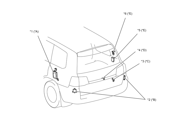
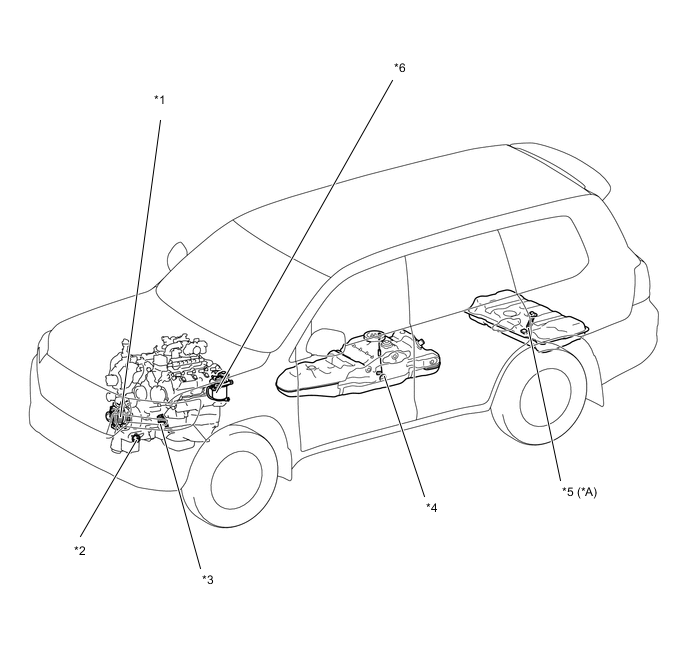
*A Models with 4-wheel Active Height Control Suspension *B Models with Blind Spot Monitor System *C Models with Tire Carrier *D Models with Multi-terrain Monitor System *E Models with Power Back Door System - - *1 Suspension Control ECU *2 Blind Spot Monitor Sensor *3 Tire Carrier Courtesy Light Switch *4 Rear View Camera (Television Camera with Dynamic Guide Line Assembly) *5 No. 2 Multiplex Network Body ECU *6 Multiplex Network Door Computer Figure 3. Models with 1GR-FE Engine
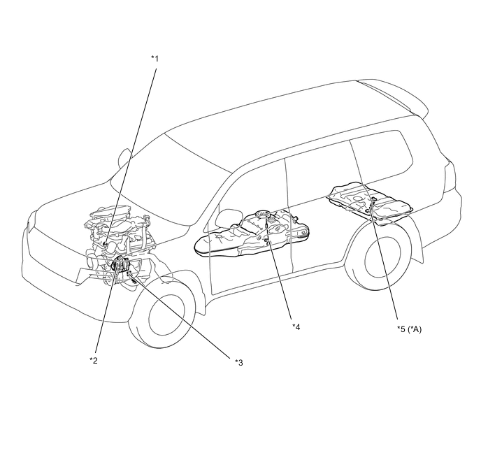
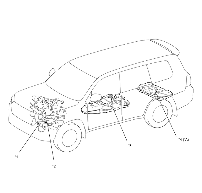
*A Models with Fuel Sub Tank Sub-assembly - - *1 Oil Pressure Sender Gage Assembly *2 Generator Assembly *3 Engine Oil Level Sensor *4 Fuel Sender Gage Assembly *5 No. 2 Fuel Sender Gage Assembly* - - Figure 4. Models with 1UR-FE Engine
*A Models with Fuel Sub Tank Sub-assembly - - *1 Generator Assembly *2 Oil Pressure Sender Gage Assembly *3 Engine Oil Level Sensor *4 Fuel Sender Gage Assembly *5 No. 2 Fuel Sender Gage Assembly - - Figure 5. Models with 1VD-FTV Engine
*A Models with Fuel Sub Tank Sub-assembly - - *1 Generator Assembly *2 Oil Pressure Sender Gage Assembly *3 Engine Oil Level Sensor *4 Fuel Sender Gage Assembly *5 No. 2 Fuel Sender Gage Assembly *6 Fuel Filter Assembly Figure 6. Models with 3UR-FE Engine
*A Models with Fuel Sub Tank Sub-assembly - - *1 Oil Pressure Sender Gage Assembly *2 Engine Oil Level Sensor *3 Fuel Sender Gage Assembly *4 No. 2 Fuel Sender Gage Assembly 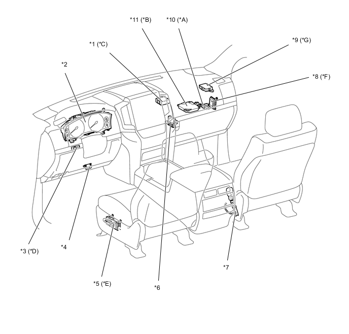
*A Models with Toyota Parking Assist-sensor System *B Models with Multi-terrain Monitor System *C Models with Variable Flow Control Power Steering *D Models with Multi-information Display *E Models with Memory System *F Models with 3UR-FE Engine *G Models with Cenral Gateway ECU - - *1 Power Steering ECU Assembly *2 Combination Meter Assembly *3 Light Control Rheostat *4 DLC3 *5 Front Power Seat Switch LH *6 Air Conditioning Amplifier Assembly *7 Front Seat Inner Belt Assembly RH *8 Transmission Control Computer Assembly *9 Central Gateway ECU *10 Clearance Warning ECU Assembly *11 Parking Assist ECU - - 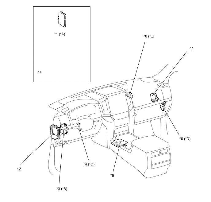
*A Models with Entry and Start System *B Models with Variable Gear Ratio Steering System *C Models with Power Tilt and Power Telescopic Steering Column *D Models with Dynamic Automatic Headlight Beam Level Control System *E Models with Pre-crash Safety System - - *1 Smart Key ECU Assembly *2 Main Body ECU (Multiplex Network Body ECU) *3 Steering Control ECU *4 Multiplex Tilt and Telescopic ECU *5 Airbag Sensor Assembly *6 Headlight Swivel ECU Assembly *7 4 Wheel Drive Control ECU *8 Driving Support Computer Assembly *a Refer to the Service Bulletin for the installation position of the part. - - 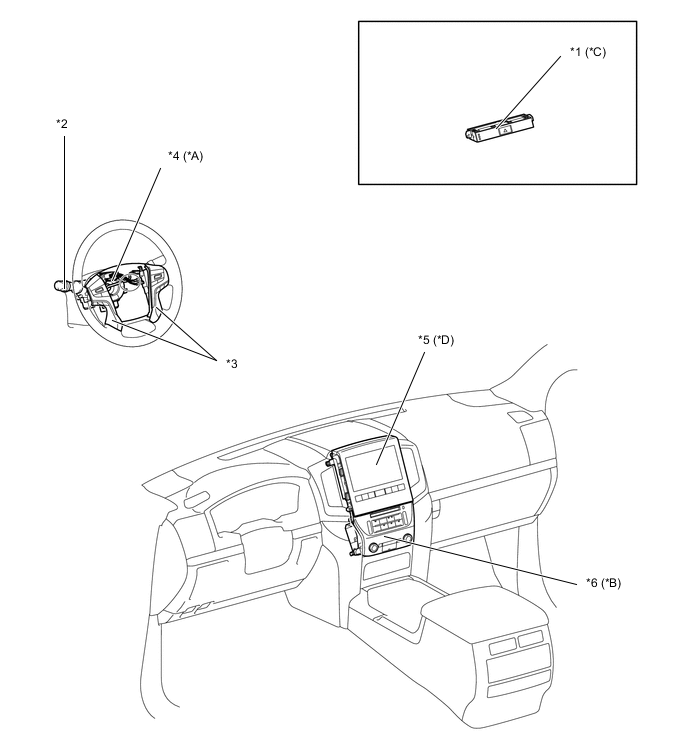
*A Models with Steering Sensor *B Models with Multi-media Module Receiver Assembly *C Models with Clock Assembly *D Models with Multi-display Assembly *1 Clock Assembly *2 Headlight Dimmer Switch Assembly *3 Steering Pad Switch Assembly *4 Spiral Cable Sub-assembly- Steering Sensor *5 Multi-display Assembly *6 Multi-media Module Receiver Assembly -
Function
-
Multi Buzzer
-
The table below shows the warning and reminder functions of the buzzer in the combination meter assembly.
Priority Item 1 Driver Seat Belt Warning (Maximum 5 Times) 2 Entry and Start System Warning 1 (Intermittent) 3 Entry and Start System Warning (Continuous) 4 Driver Seat Belt Warning (Once) 5 Front Passenger Seat Belt Warning (Once) 6 Front Seat Belt Warning (Level 2) 7 Front Seat Belt Warning (Level 1) 8 Key Reminder 9 Brake Control System Power Low Warning 10 Brake Fluid Low Warning 11 Engine Switch Operation while Driving Warning 12 Parking Brake Engaged Warning 13 Lane Departure Alert Drift Break Awakening Buzzer 14 Brake System Temperature Rise Warning/Active Test 15 Hill-start Assist Control (Level 1) Finish 16 Speed Limiter Warning 17 Door Open while Driving Warning 18 Entry and Start System Warning 2 (Intermittent) 19 Hill-start Assist Control (Level 1) Indication 20 Engine Start while Driving Notice 21 Hill-start Assist Control (Level 2) Reset 22 Sport Shift Reject Warning 23 Dynamic Radar Cruise Control Cancelation due to Low Speed without Leading Vehicle Warning 24 Dynamic Radar Cruise Control Cancelation due to Low Speed Warning 25 Lane Departure Alert Warning 26 Engine Coolant High Temperature Warning 27 Check Engine Warning 28 Multi-information Display Warning 29 Sedimenter Warning 30 VSC Side Slip Warning 31 4WD Warning (Intermittent) 32 4WD Warning (3 Times) 33 Brake System Temperature Warning/CRAWL Cancel Warning 34 Hill-start Assist Control (Level 2) Set 35 Light Reminder 36 Slide Roof Warning 37 Road Sign Assist Warning 38 Entry and Start System Warning (Once) 39 Immobiliser Certification Reminder 40 Turn Signal/Hazard Warning Operation Tech Tips
The buzzer differs by vehicle specification.
-
-
Multi-information Display (Optitron Display Type Combination Meter Assembly)
-
Display Function Flow
-
The multi-information display can be switched as shown in the flowchart below:
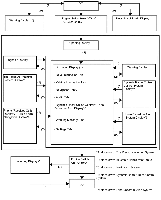
(1) Conditions are not met. (2) Conditions are met. (3) If there are multiple display requests, items will be displayed in sequence. (4) Item or display is selected by operating the steering pad switch assembly switch. (5) After engine switch is turned on (IG). -
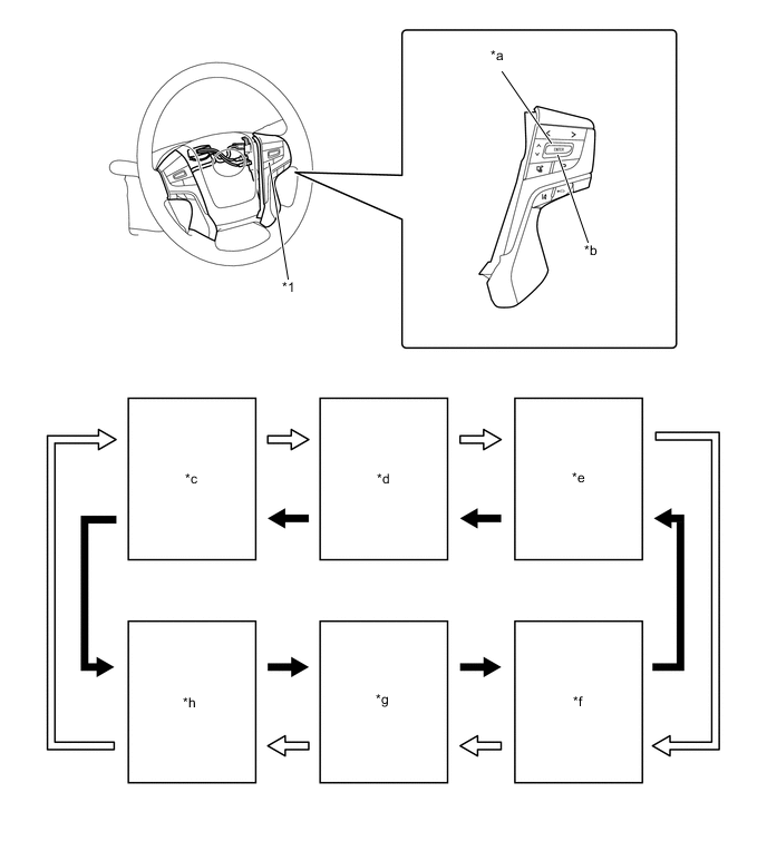
Display Tab Operation
-
The information currently displayed can be switched using the RIGHT/LEFT switch on the steering pad switch assembly.
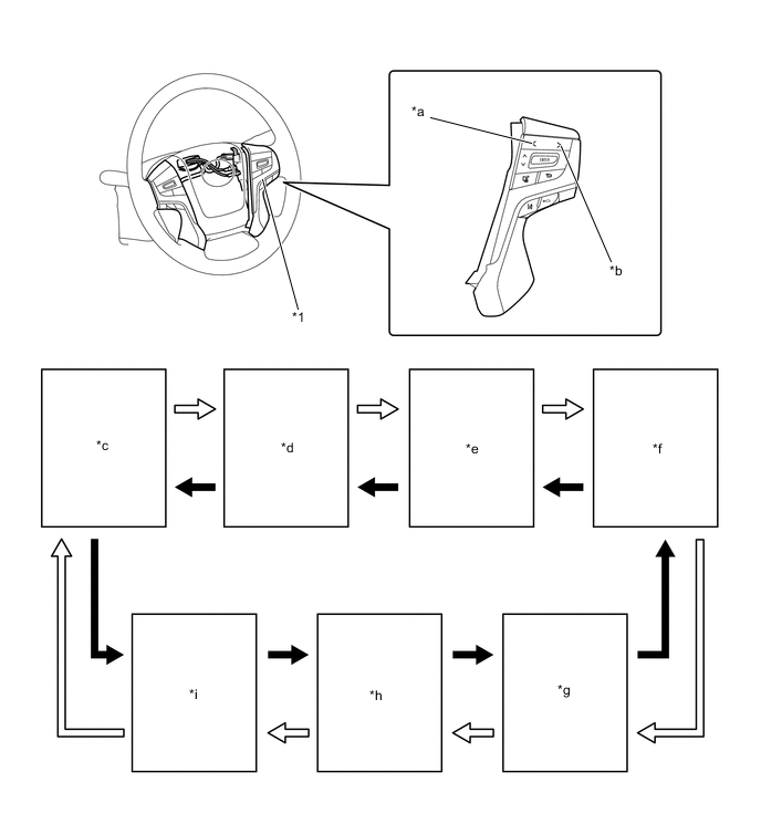
*1 Steering Pad Switch Assembly - - *a LEFT Switch *b RIGHT Switch *c Drive Information *d Vehicle Information *e Navigation Information (Models with Navigation System) *f Audio Information *g Dynamic Radar Cruise Control System/Lane Departure Alert System Information (Models with Dynamic Radar Cruise Control System or Lane Departure Alert System) *h Warning Message *i Settings - - 
RIGHT Switch Operation 
LEFT Switch Operation -
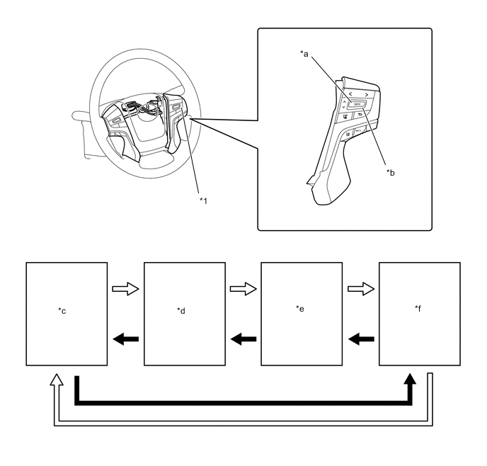
Drive Information
-
Drive information shows vehicle information such as drivable range and fuel consumption.
-
The drive information can be switched using the UP/DOWN switch on the steering pad switch assembly.
*1 Steering Pad Switch Assembly - - *a UP Switch *b DOWN Switch *c Drive Information 1 *d Drive Information 2 *e Eco Driving Indicator Zone Display (Models with Eco Driving Indicator Zone Display) *f Digital Vehicle Speed *g Drift Degree (Models with Lane Departure Alert System) *h Blank DOWN Switch Operation UP Switch Operation -
Vehicle Information
-
Vehicle information shows vehicle information such as door open.
*1 Steering Pad Switch Assembly - - *a UP Switch *b DOWN Switch *c Steering Angle/Door Open/Toyota Parking Assist-sensor System (Models with Toyota Parking Assist-sensor System) *d Tire Pressure (Models with Tire Pressure Warning System) *e DPF Indicator (Models with Diesel Engine) *f Oil Maintenance DOWN Switch UP Switch -
Setting Function
-
The items displayed on the multi-information display can be customized.
-
The items can be selected on the information setting screen.
Item Available Setting Lane Departure Alert System*1 Warning Type The warning type can be changed:
-
Small Vibration
-
Medium Vibration
-
Strong Vibration
-
Sound
Warning Timing The warning timing can be changed:
-
High
-
Normal
Drift Warning The drift warning can be switched:
-
ON
-
OFF
Drift Warning Sensitivity The drift warning sensitivity can be changed:
-
High
-
Normal
-
Low
]Blind Spot Monitor System*2 Blind Spot Monitor System The blind spot monitor system can be switched:
-
ON
-
OFF
Rear Cross Traffic Alert System The rear cross traffic alert system can be switched:
-
ON
-
OFF
Road Sign Assist*3 Road Sign Assist The road sign assist can be switched:
-
ON
-
OFF
Excess Speed Notification Method The excess speed notification method can be changed:
-
No Notification
-
Only Visual
-
Visual and Audible
Excess Speed Notification Level The excess speed notification level can be changed:
-
10 km/h (5 MPH)
-
5 km/h (3 MPH)
-
2 km/h (1 MPH)
Other Notifications Method The other road sign notification method can be changed:
-
No Notification
-
Only Visual
-
Visual and Audible
Oil Maintenance The oil maintenance information memorized in the combination meter assembly can be reset. Meter Setting Language The language used on the multi-information display can be selected:
-
Japanese
-
English (AMERICAN)
-
English (BRITISH)
-
French
-
Spanish
-
Germany
-
Italian
-
Russian
-
Turkish
-
Chinese (SIMPLIFIED)
-
Chinese (TRADITIONAL)
Tech Tips
The selectable languages may differ depending on the model or region
Unit The unit displayed on the multi-information display can be selected:
-
km (km/L)
-
km (L/100 km)
-
miles (MPG)
Tech Tips
The selectable units may differ depending on the model.
Eco Driving Indicator Light*4 The Eco Driving Indicator Light can be switched:
-
ON
-
OFF
TOP Switch Settings The switch setting can be changed. Drive Information 1 2 items can be selected among the following:
-
Current Fuel Consumption (Bar Display/Numerical Display)
-
Average Fuel Consumption (Between Reset Operations/After Engine Start-up/After Refueling Display)
-
Average Vehicle Speed (Between Reset Operations/After Engine Start-up)
-
Elapsed Time (Between Reset Operations/After Engine Start-up) - Driveable Distance
-
Cruising Range After Engine Start-up
Drive Information 2 2 items can be selected among the following:
-
Current Fuel Consumption (Bar Display/Numerical Display)
-
Average Fuel Consumption (Between Reset Operations/After Engine Start-up/After Refueling Display)
-
Average Vehicle Speed (Between Reset Operations/After Engine Start-up)
-
Elapsed Time (Between Reset Operations/After Engine Start-up)
-
Driveable Distance
-
Cruising Range After Engine Start-up
Interruption Display The following displays can be switched to ON or OFF:
-
Turn-by-turn Navigation Display*5
-
Incoming Telephone Display*6
Interruption Display The accent color can be changed:
-
Clear Blue
-
Clear Turquoise
-
Deep Orange
-
Radiant Orange
Initialization The set items can be initialized. *1: Models with lane departure alert system
*2: Models with blind spot monitor system
*3: Models with road sign assist
*4: Models with eco driving indicator light
*5: Models with navigation system
*6: Models with Bluetooth hands-free control
-
-
Warning Mode Function
-
When a warning is necessary, the warning display interrupts the display in the multi-information display.
-
The master warning light may illuminate or blink and the buzzer in the combination meter assembly may sound depending on the item displayed on the multi-information display.
Priority Display Master Warning Light Buzzer 1 4WD
Test Mode
- - VGRS
TEST MODE
- - 4-WHEEL AHC
TEST MODE
- - ADJUSTING
FRONT RADAR BEAM
- - CHECKING PRE-CRASH
BRAKE
- - CHECKING CRUISE CONTROL BRAKE - - Headlight system
Uninitialized
Visit Your Dealer
- - BRAKE! - - Push and Hold
Engine Switch for
Emergency Stop
Blinks Sounds Shift to N
and Press
Engine Switch
to Restart
Blinks Sounds 2 Graphic Display (Dynamic radar cruise control system proximity warning and lane departure alert system warning has been superposed and displayed.) - - CRAWL
Has Been Deactivated
Illuminates - Turn Assist Function
Has Been Deactivated
Illuminates - Shift to P
Before Exiting
Vehicle
Blinks Sounds 3 Graphic Display (Door Open (while driving)) Blinks Sounds Graphic Display (Door Open) - - Graphic Display (Ultra sonic sensor detection states have been superposed and displayed by door open display (while driving) or door open display.) - - Parking Assist
Malfunction
Illuminates - Clean
Parking Assist
Sensor
Illuminates - Parking Assist
Malfunction
Visit Your Dealer
Illuminates Sounds 4 Power Turned
Off to Save
Battery
- - 5 Release
Parking Brake
Blinks Blinks Key Not
Detected
Check Key
Location
Blinks Blinks Release
Accelerator
Blinks Blinks 6 Speed Limit
Exceeded
Blinks Blinks 7 Check Engine
Visit Your Dealer
Illuminates Sounds Check Engine
Reduced Engine
Power
Visit Your Dealer
Illuminates Sounds Reduced Engine
Power
Visit Your Dealer
Illuminates Sounds Engine maintenance required
Visit Your Dealer
Illuminates Sounds Radar Cruise
Control
Unavailable
Clean Sensor
Illuminates Sounds Forward Camera
System
Unavailable
Clean Windshield
- Sounds Radar Cruise
Control
Unavailable
Illuminates Sounds Smart Entry &
Start System
Malfunction
See Owner's Manual
Blinks Sounds Blind Spot
Monitor
Unavailable
Illuminates Sounds Cruise Control
Malfunction
Visit Your Dealer
Illuminates Sounds Lane Departure
Alert
Malfunction
Visit Your Dealer
- Sounds Forward Camera
System
Unavailable
- Sounds Pre-crash Safety
Malfunction
Visit Your Dealer
Illuminates Sounds Blind Spot
Monitor System
Malfunction
Visit Your Dealer
Illuminates Sounds Transmission
Fluid Temp High
See Owner's
Manual
Illuminates Sounds Transmission System
Malfunction
Visit Your Dealer
Illuminates Sounds VGRS System
Malfunction
Visit Your Dealer
Illuminates Sounds 4-WHEEL AHC System
Malfunction
Visit Your Dealer
Illuminates Sounds 8 Lane Departure
Alert
Unavailable
Below Approx.
50km/h
- - Lane Departure
Alert
Unavailable
Below Approx.
32 MPH
- - Graphic Display (Dynamic radar cruise control system and lane departure alert system has been superposed and displayed.)Alert - - Pre-crash Safety
Turned Off
- - Graphic Display (Detection Range Switching (FAR) of Pre-crash Safety System) - - Graphic Display (Detection Range Switching (MID) of Pre-crash Safety System) - - Graphic Display (Detection Range Switching (NEAR) of Pre-crash Safety System) - - Turn Off
Vehicle
Blinks Sounds Key Left
inside Vehicle
Blinks Sounds Turn Lights Off Blinks Sounds Window Open Blinks Sounds Window/
Moon Roof Open
Blinks Sounds Depress Brake and
Then Touch Key to
Engine Switch
Blinks Sounds Depress Brake and
Then Start
Engine
- - Depress Brake and
Then Start
Engine
- Sounds Lane Departure Alert
Unavailable
- Sounds 9 Steering
Wheel Lock
Press Engine
Switch while
Turning Wheel
Blinks Sounds CRAWL Not Available
Select L4
and Shift to
(D) or (R) Position
- - CRAWL Not Available
Check System
Operation Conditions
- - Turn Assist Function
Not Available
Check System
Operation Conditions
- - Turn Assist Function
Not Available
Activate CRAWL Control
- - Drive-Start
Control
Malfunction
Visit Your Dealer
Illuminates Sounds Brake Override
Malfunction
Visit Your Dealer
Illuminates Sounds 10 Key Battery Low Illuminates Sounds DRAIN WATER
FROM FUEL FILTER
Illuminates Sounds Engine Oil
Level Low
Add or Replace
Illuminates Sounds Headlight System
Malfunction
Visit Your Dealer
Illuminates Sounds To Activate Auto
High Beam, Switch
Headlights to
High Beam
Illuminates Sounds Road Sign Assist
System
Malfunction
Visit Your Dealer
Illuminates Sounds DPF full
Engine service
Required
Illuminates - Accelerator and
Brake Pedals
Depressed
Simultaneously
Blinks - Graphic Display (Tire Pressure Monitor) - - 11 Fuel filter
Maintenance
Required
- - Fuel System
Malfunction
Visit Your Dealer
Illuminates Sounds VGRS System
Malfunction
Visit Your Dealer
Illuminates - Windshield
Washer Fluid
Low
- - Fuel Low - - Would You Like to Take Rest? - Sounds Please Take Rest - Sounds Oil Maintenance Required Soon - - Oil Maintenance Required
Visit Your Dealer
High Beam
- - To Activate Auto
High Beam, Switch
Headlights to
- - Depress Brake and
Then Start
Engine
- - VSC Turned Off
Pre-crash Brake
System
Unavailable
- - Pre-crash Safety
Unavailable
- - Forward Camera System
Unavailable
- - Front Camera System
Unavailable
Clean Windshield
- - Pre-crash Safety
Unavailable
Wait a Moment
- - Pre-crash Safety
Unavailable
Clean Radar
- - DPF full
See Owner's
Manual
- - DPF Manual
Regeneration
in process
- - Theft Sensor
Turned Off
- - Theft Sensor
Turned On
- - Tech Tips
The items displayed differ by vehicle specification.
-
-
-