NEW FEATURES
-
CAN
-
The configuration of the CAN communication system has been changed.
-
A central gateway ECU has been adopted and configured into the CAN communication system for collectively controlling the CAN buses.
-
System Diagram
Figure 1. Sub Bus 15 (Models with 3UR-FE Engine)

*1 Transmission Control Computer Assembly *2 to/from Bus 2
-
Models with Central Gateway ECU
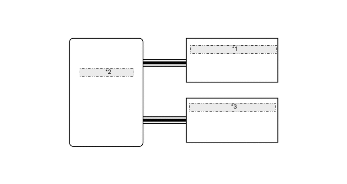
Figure 2. Bus 5

Figure 3. Bus 3
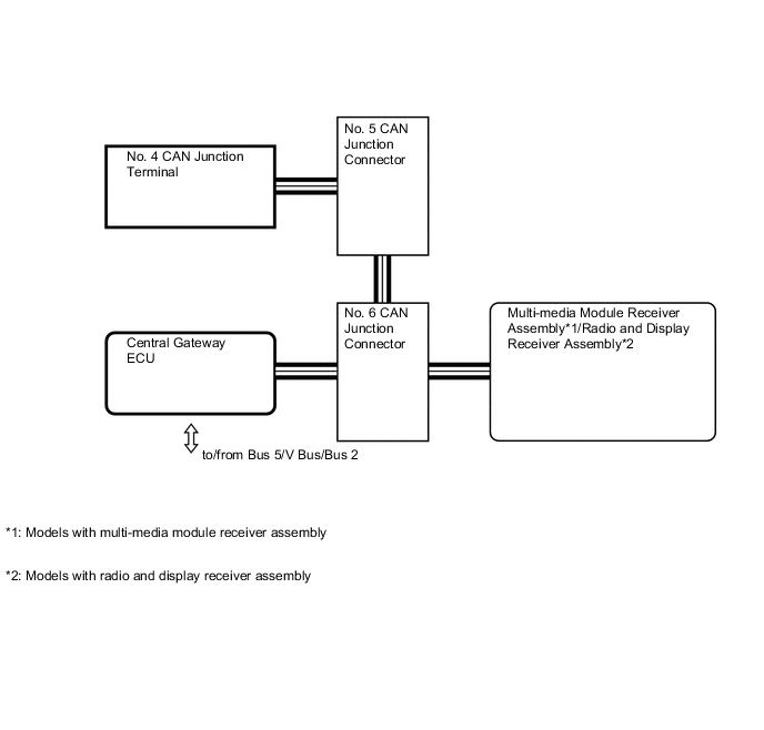
Figure 4. V Bus

*1 Central Gateway ECU *2 to/from Bus 5/Bus 3/Bus 2 Figure 5. V1 Bus for LHD

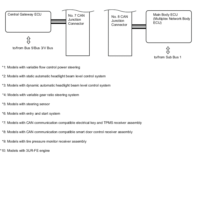
Figure 6. Bus 2 for RHD
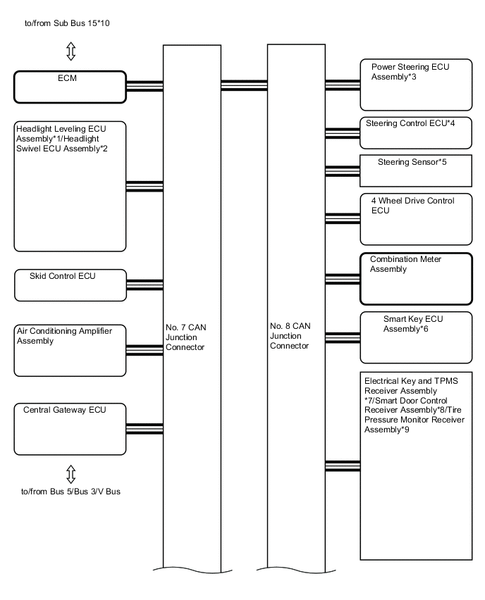

Figure 7. Sub Bus 1 for LHD
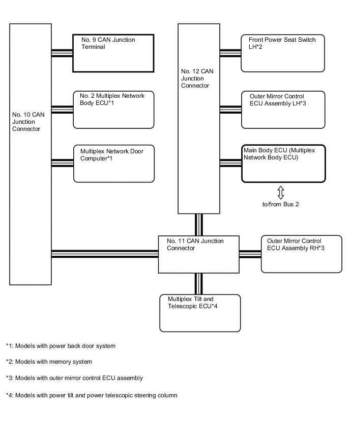
Figure 8. Sub Bus 1 for RHD

Figure 9. Local Bus

Figure 10. Local Bus

Figure 11. Local Bus (Models with Blind Spot Monitor System)

*1 Blind Spot Monitor Sensor LH *2 Blind Spot Monitor Sensor RH -
Models without Central Gateway ECU
Figure 12. V Bus for LHD

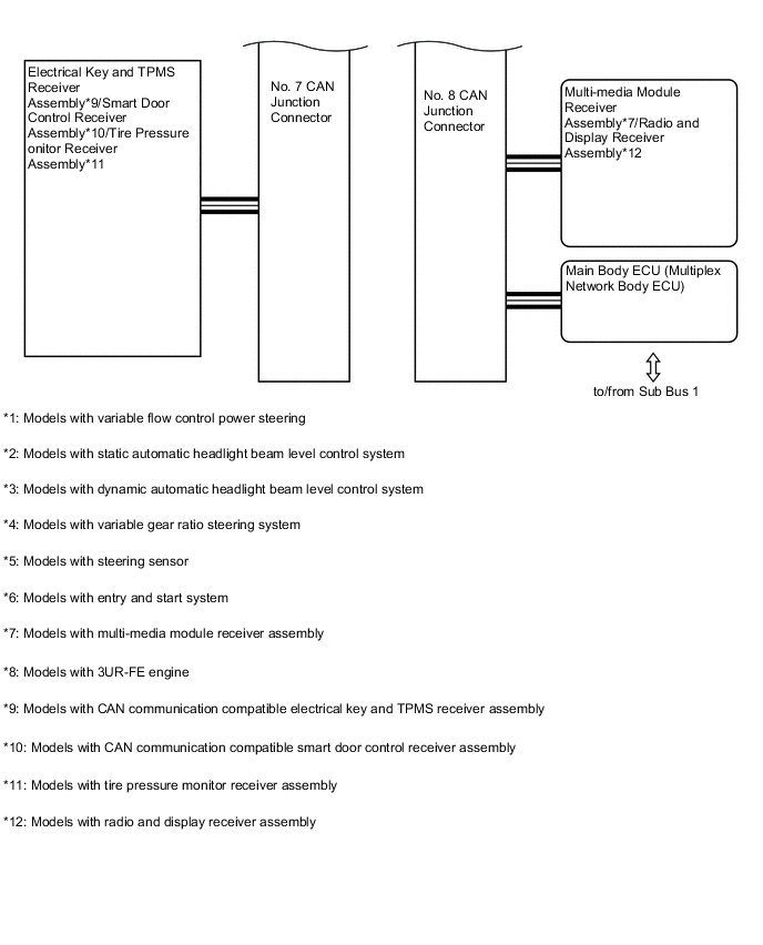
Figure 13. V Bus for RHD


Figure 14. Sub Bus 1 for LHD

Figure 15. Sub Bus 1 for RHD

-
Layout of Main Components

*A Models with Side View Camera (Television Camera with Dynamic Guide Line Assembly) *B Models with Outer Mirror Control ECU Assembly *C Models with Pre-crash Safety System *D Models with Multi-terrain Monitor System *E Models with CAN Communication Compatible Inner Rear View Mirror Assembly *F Models with CAN Communication Compatible Electrical Key and TPMS Receiver Assembly *G Models with Forward Recognition Camera - - *1 Outer Rear View Mirror Assembly RH *2 Outer Mirror Control ECU Assembly RH *3 ECM *4 Millimeter Wave Radar Sensor Assembly *5 Front Television Camera Assembly *6 Skid Control ECU *7 Inner Rear View Mirror Assembly *8 Outer Mirror Control ECU Assembly LH *9 Outer Rear View Mirror Assembly LH *10 Electrical Key and TPMS Receiver Assembly *11 Forward Recognition Camera - - 
*A Models with 4-wheel Active Height Control Suspension *B Models with Blind Spot Monitor System *C Models with Multi-terrain Monitor System *D Models with Power Back Door System *1 Suspension Control ECU *2 Blind Spot Monitor Sensor *3 Rear View Camera (Television Camera with Dynamic Guide Line Assembly) *4 No. 2 Multiplex Network Body ECU *5 Multiplex Network Door Computer - - 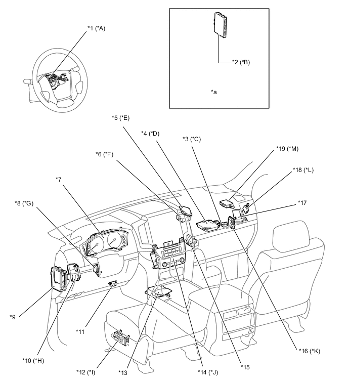
*A Models with Steering Sensor *B Models with Entry and Start System *C Models with Toyota Parking Assist-sensor System *D Models with Multi-terrain Monitor System *E Models with Pre-crash Safety System *F Models with Variable Flow Control Power Steering *G Models with Power Tilt and Power Telescopic Steering Column *H Models with Variable Gear Ratio Steering System *I Models with Memory System *J Models with Multi-media Module Receiver Assembly *K Models with 3UR-FE Engine *L Models with Static Automatic Headlight Beam Level Control System *M Models with Central Gateway ECU - - *1 Steering Sensor *2 Smart Key ECU Assembly *3 Clearance Warning ECU Assembly *4 Parking Assist ECU *5 Driving Support Computer Assembly *6 Power Steering ECU Assembly *7 Combination Meter Assembly *8 Multiplex Tilt and Telescopic ECU *9 Main Body ECU (Multiplex Network Body ECU) *10 Steering Control ECU *11 DLC3 *12 Front Power Seat Switch LH *13 Airbag Sensor Assembly *14 Multi-media Module Receiver Assembly *15 Air Conditioning Amplifier Assembly *16 Transmission Control Computer Assembly *17 4 Wheel Drive Control ECU *18 Headlight Leveling ECU Assembly *19 Central Gateway ECU - - *a Refer to the Service Bulletin for the installation position of the part. - -
-
-
-
LIN
-
Description
-
A LIN communication compatible refreshing seat switch*1, ECM*2, generator assembly*2, headlight swivel ECU assembly*3 and headlight leveling motor*3 have been adopted.
-
The refreshing seat switch*1 has been adopted to the configuration of the LIN communication for air conditioning system.
-
A LIN communication for charging system and dynamic automatic headlight beam level control system has been adopted.
-
A LIN communication for steering lock system and entry and start system has been changed.*4
-
*1: Models with heated or ventilated seat system
-
*2: Models with 3UR-FE engine
-
*3: Models with dynamic automatic headlight beam level control system
-
*4: Models with entry and start system
-
-
-
System Diagram
Figure 16. Air Conditioning System
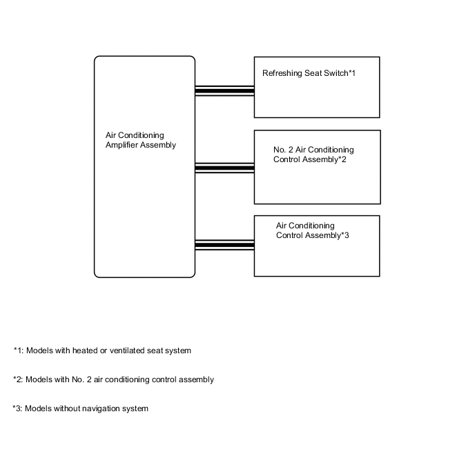
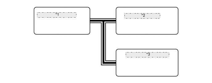
Figure 17. Charging System (Models with 3UR-FE Engine)

*1 Generator Assembly Figure 18. Steering Lock System and Entry and Start System (Models with Entry and Start System)
*1 Smart Key ECU Assembly *2 Immobiliser Code ECU *3 Steering Lock Actuator Assembly Figure 19. Dynamic Automatic Headlight Beam Level Control System (Models with Dynamic Automatic Headlight Beam Level Control System)
*1 Headlight Leveling Motor LH *2 Headlight Swivel ECU Assembly *3 Headlight Leveling Motor RH -
Layout of Main Components

*A Models with Heated or Ventilated Seat System *B Models with No. 2 Air Conditioning Control Assembly *C Models without Navigation System *D Models with Entry and Start System *E Models with Dynamic Automatic Headlight Beam Level Control System - - *1 Refreshing Seat Switch *2 Steering Lock Actuator Assembly *3 No. 2 Air Conditioning Control Assembly *4 Air Conditioning Control Assembly *5 Headlight Swivel ECU Assembly *6 Air Conditioning Amplifier Assembly *7 Smart Key ECU Assembly *8 Immobiliser Code ECU *a Refer to the Service Bulletin for the installation position of the part. - - 
*A Models with 3UR-FE Engine *B Models with Dynamic Automatic Headlight Beam Level Control System *1 Generator Assembly *2 Headlight Leveling Motor *3 ECM - -
-