NEW FEATURES
-
General
-
Outline
-
Since tire pressure decreases over time, regular adjustments are necessary. When the tire pressure warning system detects that the tire inflation pressure has dropped lower than a threshold, it will illuminate the tire pressure warning light to warn the driver.
-
A direct-sensing type tire pressure warning system is used. Also, a tire inflation pressure display function is provided on models with the tire inflation pressure display function.
-
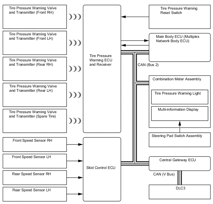
The 5 tire pressure warning valve and transmitters each send tire inflation pressure, temperature and ID code information to the tire pressure warning ECU and receiver.
-
The tire pressure warning ECU and receiver, which consists of an antenna, a receiver and an ECU, monitors the tire pressure warning valve and transmitters to detect low tire pressure in each of the 5 tires.
-
The operation of the tire pressure warning system includes a tire inflation pressure display function, warning function, initial check function, initialization function and diagnosis function.
-
The tire inflation pressure display function is a function that displays the pressure of each tire together with the position of the identified tire on the multi-information display.
-
The transmission cycle with which the information is sent from a tire pressure warning valve and transmitter to the tire pressure warning ECU and receiver is determined as follows based on the travel mode and the acceleration sensor built into each tire pressure warning valve and transmitter. Since the acceleration sensor is used only to determine if the vehicle is being driven, the value of rotational acceleration is not sent to the tire pressure warning ECU and receiver.
Travel Mode Transmission Cycle While stopped*1 1 time / 1.5 min While traveling*2 4 times / 1 min or equivalent *1: When G that is applied to the acceleration sensor is less than 8G.
*2: When G that is applied to the acceleration sensor is 8G or greater.
-
According to the vehicle driving conditions in an initialization, both the warning threshold and cancellation threshold may be higher than the recommended threshold. Therefore, when a decreased tire pressure warning is activated, the warning may not stop even though the tire inflation pressure has been adjusted to the recommended pressure. In this case, perform initialization.*
-
*: Models compliant with ECE-R64 legal regulations
-
-
-
Precaution
-
The system is disabled in the following conditions: (When the condition becomes normal, the system will work properly.)
-
When all of the tires and wheels that have the tire pressure warning valve and transmitters registered with the tire pressure warning ECU and receiver have not been installed.
-
When all of the transmitter ID codes are not registered with the tire pressure warning ECU and receiver.
-
When the tire pressure is 380 kPa (55 psi, 3.9 kgt/cm2) (relative pressure) or more.
-
When the transmitter battery is depleted. (Battery life: approximately 10 years)
-
-
The system may become disabled in the following conditions: (When the condition becomes normal, the system will work properly.)
-
When electric devices or facilities using similar radio frequencies are nearby.
-
When a wireless device or other equipment operating at a similar frequency is in use in the vehicle.
-
When a window tint that affects radio wave signals is installed.
-
When there is a lot of snow or ice on the vehicle, in particular, around the wheels or wheel housings.
-
When non-genuine wheels are used.
-
When tire chains are used.
-
When aftermarket tire repair sealant is used.
-
-
The tire pressure warning system may not function properly if aftermarket tire repair sealant has been used to repair a flat tire. If this type of sealant has been used, the tire pressure warning valve and transmitter should be replaced with a new one after repairing or replacing the tire.
-
The tire pressure warning light may illuminate due to natural pressure loss caused by air passing through the tires or by changes in tire pressure caused by temperature fluctuations. When adjusting tire pressure, please be aware of the driving conditions and temperature conditions. The tire warning light is prone to illuminate especially in late autumn and during winter.
-
-
-
System Diagram
Figure 1. Models without Tire Inflation Pressure Display Function
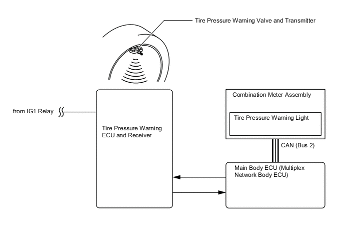
Figure 2. Models with Tire Inflation Pressure Display Function
-
Parts Location
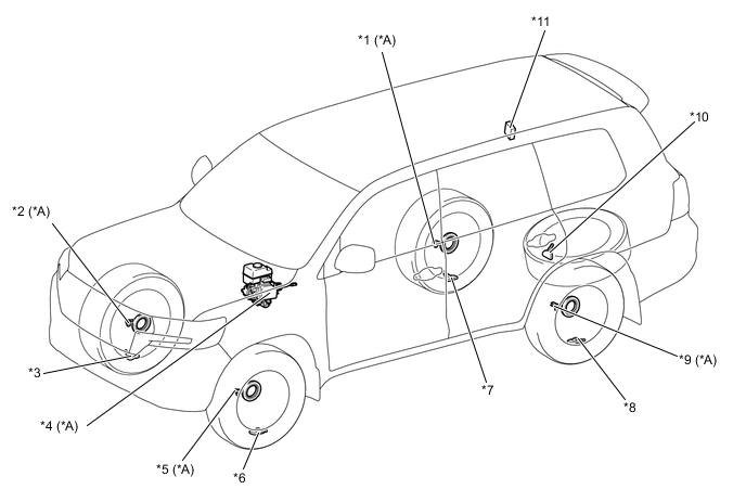
*A Models with Tire Inflation Pressure Display Function - - *1 Rear Speed Sensor RH *2 Front Speed Sensor RH *3 Tire Pressure Warning Valve and Transmitter (Front RH) *4 Skid Control ECU *5 Front Speed Sensor LH *6 Tire Pressure Warning Valve and Transmitter (Front LH) *7 Tire Pressure Warning Valve and Transmitter (Rear RH) *8 Tire Pressure Warning Valve and Transmitter (Rear LH) *9 Rear Speed Sensor LH *10 Tire Pressure Warning Valve and Transmitter (Spare Tire) *11 Tire Pressure Warning ECU and Receiver - - 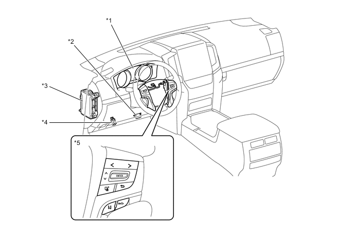
*1 Combination Meter Assembly
-
Tire Pressure Warning Light
-
Multi-information Display
*2 DLC3 *3 Main Body ECU (Multiplex Network Body ECU) *4 Tire Pressure Warning Reset Switch *5 Steering Pad Switch Assembly - - -
-
Details
-
Function of Main Components
Component Function Tire Pressure Warning Valve and Transmitter Detects the tire inflation pressure and temperature of the tire and transmits the measured value and ID code to the tire pressure warning ECU and receiver. Tire Pressure Warning ECU and Receiver
-
Receives the data from each tire pressure warning valve and transmitter and monitors its tire inflation pressure.
-
Outputs the respective signal to the main body ECU (multiplex network body ECU) when a drop in the tire inflation pressure, a system malfunction or the beginning of initialization is detected.
-
Confirms the positions of the tires in accordance with information about the intensity of radio waves for tire position determination from the tire pressure warning valve and transmitter, and sends a signal to display the tire pressure value (based on the measured value) on the multi-information display.
Tire Pressure Warning Reset Switch The current tire pressures are stored in the tire pressure warning system as set pressures when the tire pressure warning reset switch is operated. Main Body ECU (Multiplex Network Body ECU) Receives the signal from the tire pressure warning ECU and receiver and outputs it to the combination meter assembly via CAN communication. Speed Sensors* Detect the wheel speed of each of the 4 wheels and sends the 4 wheel speed signal to skid control ECU. Skid Control ECU* Transmits the 4 wheel speed signal to the tire pressure warning ECU and receiver. Combination Meter Assembly Transmits the vehicle speed signal to the tire pressure warning ECU and receiver. Combination Meter Assembly Tire Pressure Warning Light Warns the driver by illuminating or blinking for one minute in accordance with the signal from the tire pressure warning ECU and receiver. Multi-information Display* Displays the identified tire pressure and position to inform or warn the driver. Steering Pad Switch Assembly* Switches the information on the multi-information display to the tire pressure when pressed. *: Models with tire inflation pressure display function
-
-
Function
-
Tire Inflation Pressure Display Function
-
The multi-information display shows the following to inform or warn the driver of the tire pressure:
Tech Tips
This illustration is an example.
-
Tire pressure is normal.

-
Tire pressure is below the warning threshold.

-
There is a system malfunction, or tire position has not yet been completed.

-
Identification of the tire position is carried out when the engine switch is turned on (IG) or when initialization is performed. However, under certain conditions, the tire position may not be displayed. In that case, radio wave conditions may be restored by continuously driving, thereby enabling tire position determination.
-
After initialized, the tire positions will be identified by driving at least 10 minutes at a vehicle speed of at least 40 km/h.*
Tech Tips
*: When driving straightforward. Slight left and right turns are allowed. Do not drive in reverse. It may take 30 minutes to 60 minutes when driving on a rough road or in reverse.
-
-
Warning Function
-
When any of the following conditions are met, the tire pressure warning system illuminates the tire pressure warning light to warn the driver.
Warning Condition (Models Compliant with FMVSS138 Legal Regulations)
-
When the tire pressure decreases to approximately 75% or less of the default tire pressure set during system initialization.
Warning Condition (Models Compliant with ECE-R64 Legal Regulations)
-
When the tire pressure decreases to approximately 80% or less of the default tire pressure set during system initialization.
-
When the tire pressure decreases approximately 80% or less of the tire pressure when warm.
-
-
The tire pressure warning system has 2 warning methods that are used, depending on the condition detected.
-
The table below shows the warning methods for the tire pressure warning light in the combination meter assembly and the multi-information display.
Detection Condition Tire Pressure Warning Light Multi-information Display*1,*2 The tire pressure warning system has detected that the tire pressure has become lower than the warning threshold. Illuminates*3 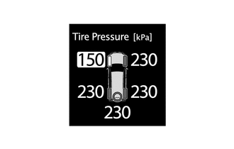
The tire pressure warning system has detected a malfunction in the system. Stays on after blinking for 1 minute*4 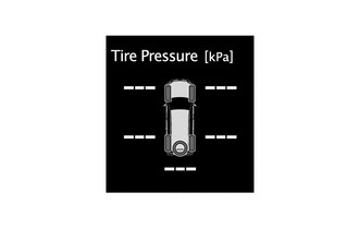
Tech Tips
*1: Models with tire inflation pressure display function
*2: This illustration is an example.
*3: If the tire pressure warning light illuminates, adjust the tire pressure.
*4: If the tire pressure warning light stays on after blinking for 1 minute, the system is malfunctioning and must be repaired in order to turn off the light. For details, refer to the Repair Manual.
-
-
Initial Check Function
-
After the ignition switch is tuned to ON, the tire pressure warning ECU and receiver illuminates the tire pressure warning light for 3 seconds to check the warning light circuits.
-
-
Initialization Function
-
The warning threshold is calculated from the tire inflation pressure valve at the time of initialization and memorized in the tire pressure warning ECU and receiver. Therefore, the tire pressure warning ECU and receiver should be initialized after:
-
The recommended tire inflation pressure changes due to changes in vehicle weight, speed conditions or tire size.
-
Replacement of the tire pressure warning ECU and receiver or a tire pressure warning valve and transmitter.
-
The tires are rotated on a vehicle with different recommended tire inflation pressures for the front and rear tires.
-
The tire pressure is adjusted.*
-
*: Models compliant with FMVSS138 legal regulations
-
Initialization starts after the tire pressure warning reset switch is pressed and held (with the engine switch on (IG) and with the vehicle stopped) and the tire pressure warning light blinks slowly 3 times.
-
Before performing initialization, adjust the tire inflation pressure to the recommended pressure when the tires are cold. For details, refer to the Repair Manual.
-
The tire pressure warning reset switch is not used to cancel the warning. Do not press the tire pressure warning reset switch to turn off the tire pressure warning light.*
-
*: Models compliant with ECE-R64 legal regulations
-
-
-
Construction
-
Tire Pressure Warning Valve and Transmitter
-
The tire pressure warning valve and transmitters are integrated in the tire valves. Each transmitter consist of a lithium battery, sensor and transmitter.
-
Make sure not to damage the urethane covered backside of the transmitter (the surface opposite to the side with the ID code) with anything sharp.
-
The transmitter directly measures tire pressure, temperature, and centrifugal acceleration.
-
The transmitter transmits the measured tire inflation pressure and temperature values to the tire pressure warning ECU and receiver on a frequency of 315 MHz*1 or 433 MHz*2.
-
*1: Models compliant with FMVSS138 legal regulations
-
*2: Models compliant with ECE-R64 legal regulations
-
Depending on the timing of the data transmission, it may take several minutes to receive the data from the tire pressure warning valve and transmitter.
-
The ID code is written on the tire pressure warning valve and transmitter.
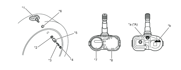
*A Models with Tire Inflation Pressure Display Function - - *1 Tire Pressure Warning Valve and Transmitter *2 Washer *3 Tire Valve Core *4 Cap *5 Nut *6 Grommet *7 Lithium Battery *8 Sensor and Transmitter *a Identification Marking *b ID Code (Hexadecimal 7 Digits)
Tech Tips
-
The lithium batteries of the tire pressure warning valve and transmitters are non-replaceable. If a battery is depleted, the tire pressure warning valve and transmitter must be replaced. (Battery life: approximately 10 years)
-
When replacing a tire pressure warning valve and transmitter, each of the tire pressure warning valve and transmitter ID codes must be registered. If even one of the transmitters is replaced, the ID codes of all tire pressure warning valves and transmitters must be registered again. Record all the existing ID codes before beginning the process to enter new ID codes.
-
To register an ID code, use the Global TechStream (GTS) to enter the ID code that is indicated on the tire pressure warning valve and transmitter.
-
Be careful not to damage the tire pressure warning valve and transmitters when removing and reinstalling them.
-
Replace the grommet, valve core, washer and nut with new ones when tire pressure warning valve and transmitter is being replaced or being removed and reinstalled. This is necessary to ensure sealing performance.
-
When replacing a valve cap, use only the specified cap. If an unspecified cap is used, it may seize to the tire pressure warning valve and transmitter.
-
For details, refer to the Repair Manual.
-
-
-
Diagnosis
-
To inform the driver when the tire pressure warning ECU and receiver detects a malfunction in the system, the tire pressure warning ECU and receiver will blink the tire pressure warning light for 1 minute, after which the light will illuminate. The tire pressure warning ECU and receiver will also store Diagnostic Trouble Codes (DTCs) in memory.
-
5-digit DTCs can be read by connecting the Global TechStream (GTS) to the DLC3. For details, refer to the Repair Manual.
-
-