NEW FEATURES
-
VARIABLE GEAR RATIO STEERING (VGRS) SYSTEM
-
General
-
An optimal power steering has been adopted through the newly adopted drive mode select, allowing the driver to switch the mode between normal and sport to improve a sense of togetherness with the vehicle through the steering responses clearly transmitted to the driver.
-
-
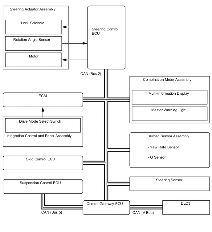
System Diagram
-
Layout of Main Components
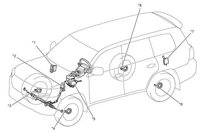
*1 ECM *2 Steering Actuator Assembly *3 Front Speed Sensor RH *4 Front Speed Sensor LH *5 Skid Control ECU *6 Rear Speed Sensor LH *7 Suspension Control ECU *8 Rear Speed Sensor RH 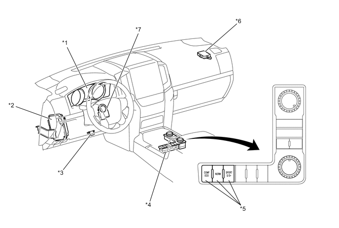
*1 Combination Meter Assembly *2 Steering Control ECU *3 DLC3 *4 Integration Control and Panel Assembly *5 Drive Mode Select Switch *6 Central Gateway ECU *7 Steering Sensor - - -
Function of Main Components
Components Function Steering Control ECU Operates the motor by calculating the operating angle of the steering actuator based on the signals from the steering angle sensor and vehicle speed sensor. Steering Actuator Assembly Motor Rotates to create the operating angle of the steering actuator upon receiving the signals from the steering control ECU. Rotational Angle Sensor Outputs the rotational angle of the motor to the steering control ECU. Lock Solenoid Locks the motor shaft so that the motor will not rotate in case of a system malfunction. Steering Sensor Detects the steering angle of the steering wheel and transmits them to the steering control ECU. Skid Control ECU
-
Transmits the vehicle speed signal to the steering control ECU.
-
Transmits the power steering cooperative control signal to the steering control ECU.
Speed Sensors Detects the wheel speed and outputs it to the skid control ECU. Combination Meter Multi-information Display Indicates "VGRS Malfunction" to inform the driver of a malfunction in the system. Master Warning Light Illuminates to warn the driver of a malfunction in the system. Buzzer Sounds to warn the driver of a malfunction in the system. Suspension Control ECU Outputs the damping force control condition. ECM
-
Outputs the engine speed.
-
Outputs the drive mode select switch signal.
Integration Control and Panel Assembly Drive Mode Select Switch Switches the drive mode (ECO, COMFORT, NORMAL, SPORT S or SPORT S+). -
-
System Control
Components Outline SPORT Mode Control The assist characteristics are switched to achieve a suitable steering feeling for SPORT S+ mode.
-