NEW FEATURES
-
OUTLINE
-
An AE80F 8-speed automatic transmission (8 Super ECT) is used.
-
A gate type shift lever is used.
-
A multi-mode automatic transmission is used.
-
A shift pattern select switch is used.*1
-
A combination switch assembly (drive mode select switch and ECT 2nd start mode switch) which can be used to select the drive modes (ECO/COMFORT, NORMAL, SPORT S, SPORT S+ or ECT 2ND START) is provided.*2
-
A water cooled oil cooler and air cooled oil cooler (oil cooler with hose assembly) are used in the ATF cooling system.
-
*1: Models with ECT POWER mode switch
-
*2: Models with drive mode select switch
-
-
-
SPECIFICATION
Automatic Transmission Assembly Gear Ratio 1st 4.795 2nd 2.811 3rd 1.844 4th 1.429 5th 1.213 6th 1.000 7th 0.817 8th 0.672 Reverse 3.785 ATF Cooling System Water Cooled Oil Cooler and Air Cooled Oil Cooler (Oil Cooler with Hose Assembly) Fluid Type Toyota Genuine ATF WS Fluid Capacity Liters (US qts, Imp. qts) 10.1 (10.7, 8.9) Weight (Reference)* kg (lb) 110 (242.7) *: Weight shows the figure with the fluid fully filled.
Planetary Gears Front Planetary Gear Unit No. of Sun Gear Teeth 38 No. of Inner Pinion Gear Teeth 16 No. of Outer Pinion Gear Teeth 19 No. of Ring Gear Teeth 83 Rear Planetary Gear Unit No. of Middle Sun Gear Teeth 38 No. of Rear Sun Gear Teeth 30 No. of Long Pinion Gear Teeth 20 No. of Short Pinion Gear Teeth 17 No. of Ring Gear Teeth 78 Friction Engagement Components and 1-way Clutch No. 1 Clutch (C1) No. of Discs 7 No. 2 Clutch (C2) 7 No. 3 Clutch (C3) 6 No. 4 Clutch (C4) 6 No. 1 Brake (B1) No. of Discs 6 No. 2 Brake (B2) 6 No. 1 1-way Clutch (F1) No. of Sprags 41 Torque Converter Assembly Torque Converter Type 3-element, 1-step, 2-phase Stall Torque Ratio 1.80 -
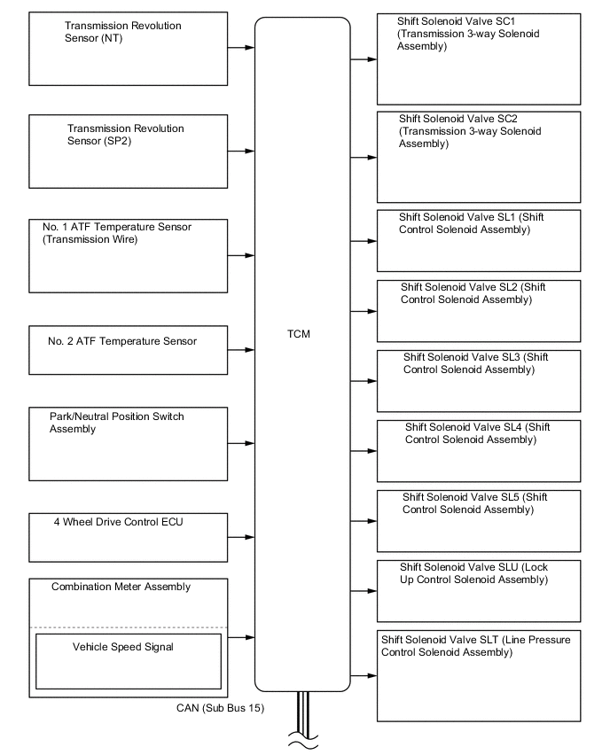
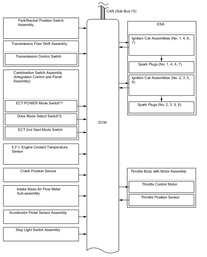
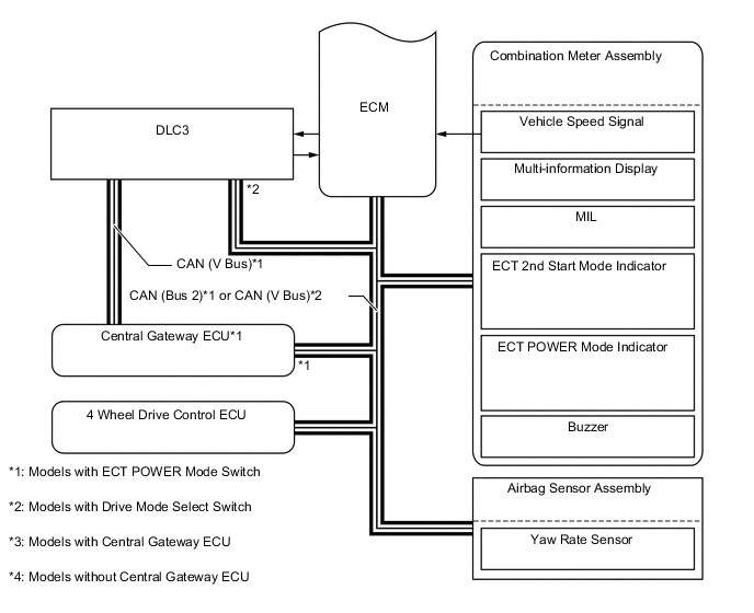
SYSTEM DIAGRAM
-
PARTS LOCATION
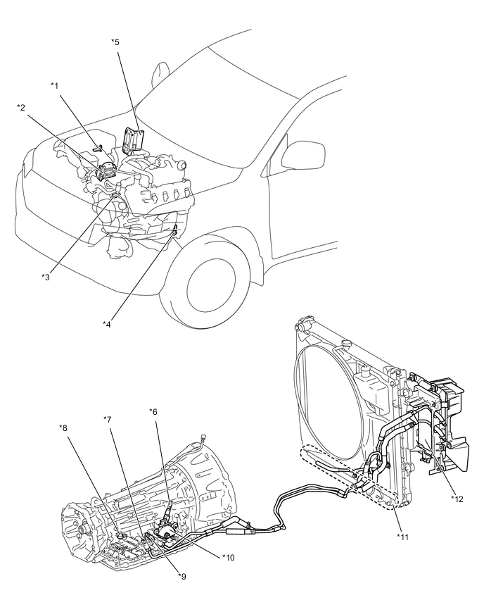
*1 Intake Mass Air Flow Meter Sub-Assembly *2 Throttle Body with Motor Assembly
-
Throttle Position Sensor
-
Throttle Control Motor
*3 E.F.I. Engine Coolant Temperature Sensor *4 Crank Position Sensor *5 ECM *6 Transmission Revolution Sensor (NT) *7 No. 1 ATF Temperature Sensor (Transmission Wire) *8 Transmission Revolution Sensor (SP2) *9 No. 2 ATF Temperature Sensor *10 Park/Neutral Position Switch Assembly *11 Water Cooled Oil Cooler (Built-In Radiator) *12 Air Cooled Oil Cooler (Oil Cooler with Hose Assembly) 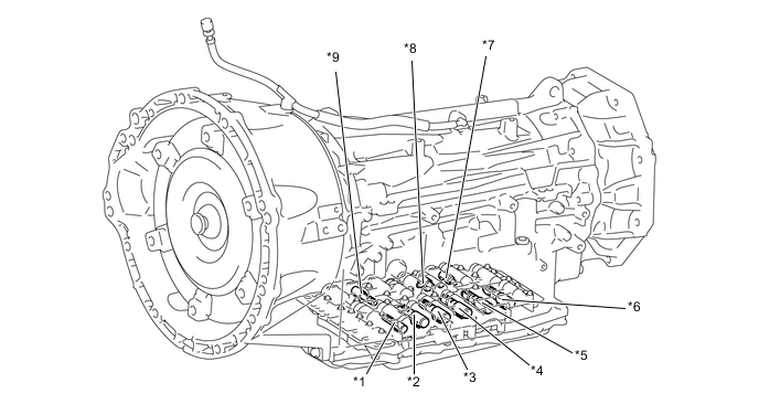
*1 Shift Solenoid Valve SLT (Line Pressure Control Solenoid Assembly) *2 Shift Solenoid Valve SL1 (Shift Control Solenoid Assembly) *3 Shift Solenoid Valve SL4 (Shift Control Solenoid Assembly) *4 Shift Solenoid Valve SL2 (Shift Control Solenoid Assembly) *5 Shift Solenoid Valve SL5 (Shift Control Solenoid Assembly) *6 Shift Solenoid Valve SL3 (Shift Control Solenoid Assembly) *7 Shift Solenoid Valve SC1 (Transmission 3-way Solenoid Assembly) *8 Shift Solenoid Valve SC2 (Transmission 3-way Solenoid Assembly) *9 Shift Solenoid Valve SLU (Lock Up Control Solenoid Assembly) - - 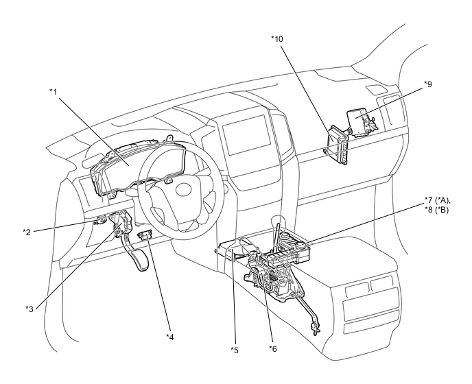
*A Models with ECT POWER Mode Switch *B Models with Drive Mode Select Switch *1 Combination Meter Assembly
-
ECT POWER Mode Indicator Light
-
ECT 2nd Start Mode Indicator Light
-
MIL
-
Multi-Information Display
-
Buzzer
*2 Stop Light Switch Assembly *3 Accelerator Pedal Sensor Assembly *4 DLC3 *5 Airbag Sensor Assembly
-
Yaw Rate Sensor
*6 Transmission Floor Shift Assembly
-
Transmission Control Switch
*7 Combination Switch Assembly (Integration Control and Panel Assembly)
-
ECT 2nd Start Mode Switch
-
ECT POWER Mode Switch
*8 Combination Switch Assembly (Integration Control and Panel Assembly)
-
ECT 2nd Start Mode Switch
-
Drive Mode Select Switch
*9 4 Wheel Drive Control ECU *10 TCM -
-
FUNCTION OF MAIN COMPONENTS
Component Function Torque Converter Assembly
-
Transmits the engine power to the transmission.
-
Increases engine torque.
Oil Pump Assembly Provides oil pressure necessary for the transmission operation. No. 1 Clutch (C1) Connects the front planetary ring gear and rear sun gear. No. 2 Clutch (C2) Connects the intermediate shaft and rear planetary carrier. No. 3 Clutch (C3) Connects the front planetary ring gear and middle sun gear. No. 4 Clutch (C4) Connects the front planetary carrier and middle sun gear. No. 1 Brake (B1) Prevents the middle sun gear from turning either clockwise or counterclockwise. No. 2 Brake (B2) Prevents the rear planetary carrier from turning either clockwise or counterclockwise. No. 1 1-way Clutch (F1) Prevents the rear planetary carrier from turning counterclockwise. Planetary Gears Change the power transmission route in accordance with clutch and brake operation, and increase or decrease output shaft revolution accordingly. Shift Solenoid Valve SL1 (Shift Control Solenoid Assembly) Controls No. 1 clutch (C1) pressure. Shift Solenoid Valve SL2 (Shift Control Solenoid Assembly)
-
Controls No. 2 clutch (C2) pressure.
-
Controls No. 2 brake (B2) pressure.
Shift Solenoid Valve SL3 (Shift Control Solenoid Assembly) Controls No. 3 clutch (C3) pressure. Shift Solenoid Valve SL4 (Shift Control Solenoid Assembly) Controls No. 4 clutch (C4) pressure. Shift Solenoid Valve SL5 (Shift Control Solenoid Assembly) Controls No. 1 brake (B1) pressure. Shift Solenoid Valve SLU (Lock Up Control Solenoid Assembly) Controls lock-up clutch pressure. Shift Solenoid Valve SLT (Line Pressure Control Solenoid Assembly) Controls line pressure. Shift Solenoid Valve SC1 (Transmission 3-way Solenoid Assembly)
-
Switches the clutch apply relay valve.
-
Switches the reverse control valve.
Shift Solenoid Valve SC2 (Transmission 3-way Solenoid Assembly) Switches the B2 relay valve. No. 1 ATF Temperature Sensor (Transmission Wire) Detects the ATF temperature. No. 2 ATF Temperature Sensor Measures the temperature of the ATF to the oil cooler. Transmission Revolution Sensor (NT) Detects the input speed of the transmission. Transmission Revolution Sensor (SP2) Detects the output speed of the transmission. Yaw Rate Sensor (Airbag Sensor Assembly)
-
Detects the vehicle's longitudinal and lateral acceleration.
-
Detects the vehicle's yaw rate.
Park/Neutral Position Switch Assembly Detects the shift lever position (P, R, N, D). Transmission Floor Shift Assembly Transmission Control Switch
-
Detects when the shift lever is in S.
-
Detects the driver's upshift and downshift operations when the shift lever is in S.
Stop Light Switch Assembly Detects when the brake pedal is depressed. Combination Switch Assembly (Integration Control and Panel Assembly) ECT POWER Mode Switch*1 Switches the ECT POWER mode. Drive Mode Select Switch*2 Switches the drive mode (ECO, COMFORT, NORMAL, SPORT S or SPORT S+). ECT 2nd Start Mode Switch Switches the ECT 2nd start mode. Combination Meter Assembly Transmits the vehicle speed signal to the ECM. Combination Meter Assembly MIL Illuminates to inform the driver when the ECM detects a malfunction. Multi-information Display
-
Displays the shift range.
-
Displays the drive mode.
-
Displays the message when the ATF is at a high temperature.
ECT POWER Mode Indicator Light Illuminates when the combination switch assembly (ECT POWER mode switch) is pressed. ECT 2nd Start Mode Indicator Light Illuminates when the combination switch assembly (ECT 2nd start mode switch) is pressed. Buzzer Sounds when downshift operation is rejected in S mode. TCM Controls each shift solenoid valve in response to a signal from each sensor and switch. ECM Controls engine output in response to signals from the TCM. *1: Models with ECT POWER mode switch
*2: Models with drive mode select switch
-
-
SYSTEM CONTROL
Electronic Control of Automatic Transmission Control Function Powertrain Cooperative Control Controls both the shift control and engine output control in an integrated way, achieving excellent shift characteristics and drivability. Shift Timing Control The TCM sends current to each shift solenoid valves based on signals from various sensors in order to shift the gears. Line Pressure Control Actuates the shift solenoid valve SLT (line pressure control solenoid assembly) to control the line pressure in accordance with information from the TCM and the operating conditions of the transmission. Clutch Pressure Optimal Control The shift solenoid valves SL1, SL2, SL3, SL4, SL5 (Shift Control Solenoid Assembly), SLT (line pressure control solenoid assembly) and SLU (lock up control solenoid assembly) precisely control the clutch pressure in accordance with the engine output and driving conditions of the transmission. Clutch to Clutch Pressure Control Controls the pressure that is applied directly to B1 brake and each clutch by actuating the shift solenoid valves SL1, SL2, SL3, SL4 and SL5 (Shift Control Solenoid Assembly) in accordance with the TCM signals. Coast Downshift Control To prevent engine speed from decreasing and thereby maintain fuel cut, the TCM performs downshifts before fuel cut ends. Lock-up Timing Control The TCM sends current to the shift solenoid valve SLU (lock up control solenoid assembly) based on signals from various sensors and engages or disengages the lock-up clutch. Flex Lock-up Clutch Control Controls the shift solenoid valve SLU (lock up control solenoid assembly), provides an intermediate mode for when the lock-up clutch is between on and off, and increases the operating range of the lock-up clutch to improve fuel economy. Multi-mode Transmission The TCM appropriately controls the automatic transmission in accordance with the shift range position selected while the shift lever is in the S mode position. Artificial Intelligence Shift Control (AI shift Control) Based on the signals from various sensors, the TCM determines the road conditions and the intention of the driver. Thus, an appropriate shift pattern is automatically determined, thus improving driveability. ECT 2nd Start Control Enabling the vehicle to take off in the 2nd gear and thus make it easy to take off snowy, sandy or muddy terrain. Differential Protection Control When there is a large rotation difference between the left and right wheels, shifting will be prevented to protect the differential. ATF High Temperature Control When the ATF is at a high temperature, normal shifting characteristics will be changed to shifting characteristics which actively utilize the low gear range to prevent the oil temperature from rising further. Engine Stall Avoidance Control Engine stall avoidance control is engaged when the engine is started again after an engine stall.
-
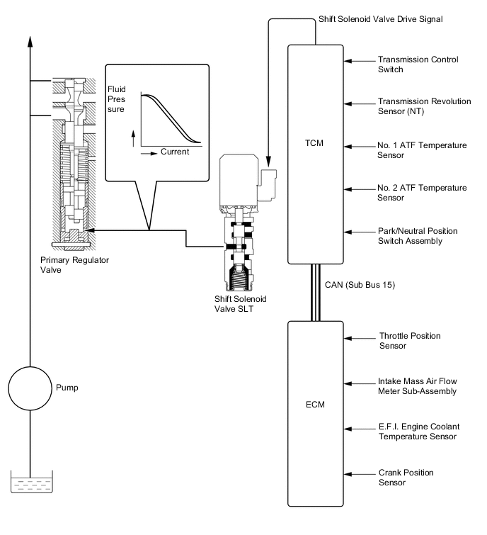
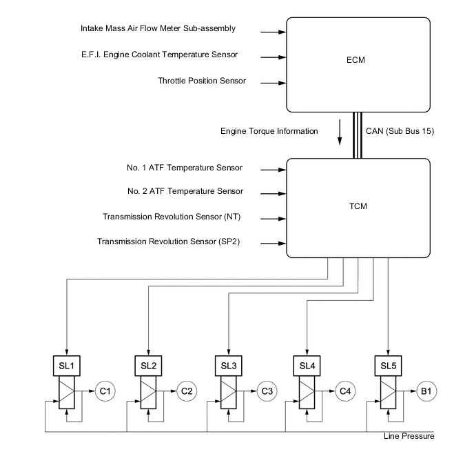
Line Pressure Control
-
The line pressure is controlled by using the shift solenoid valve SLT (line pressure control solenoid assembly). Through the use of the shift solenoid valve SLT (line pressure control solenoid assembly), the line pressure is optimally controlled in accordance with the engine torque information, as well as with the internal operating conditions of the torque converter and the transmission. Accordingly, the line pressure can be accurately controlled in accordance with the engine output, traveling condition, and ATF temperature, thus realizing smooth shift characteristics and optimizing the workload of the oil pump.
-
-
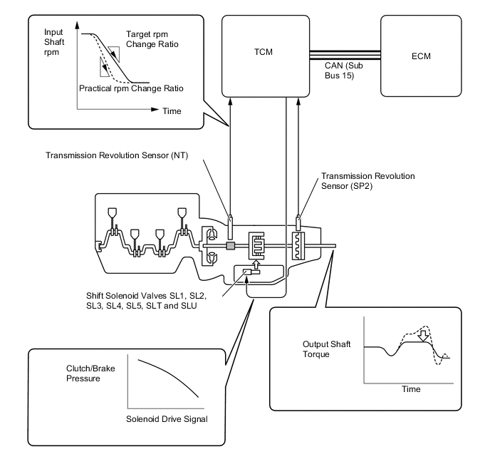
Clutch Pressure Optimal Control
-
The TCM monitors the signals from various types of sensors, such as the transmission revolution sensor (NT), allowing the shift solenoid valve SL1, SL2, SL3, SL4, SL5 (Shift Control Solenoid Assembly), SLT (line pressure control solenoid assembly) and shift solenoid valve SLU (lock up control solenoid assembly) to minutely control the clutch pressure in accordance with engine output and driving conditions. As a result, smooth shift characteristics are achieved.
-
-
Clutch to Clutch Pressure Control
-
Clutch to clutch pressure control is used for shift control. As a result, shift control in the 2nd gear or above is possible without using the 1-way clutch, and the automatic transmission has been made lightweight and compact.
-
Using the fluid pressure circuit, which enables the clutches and brakes (C1, C2, C3, C4 and B1) to be controlled independently, and the high flow SL1, SL2, SL3, SL4 and SL5 shift solenoid valves, which directly control the line pressure, the TCM controls each clutch and brake accordingly with the optimum fluid pressures and timings in accordance with the information transmitted by the sensors, and then shifts the gears. As a result, highly responsive and excellent shift characteristics have been achieved.
-
-
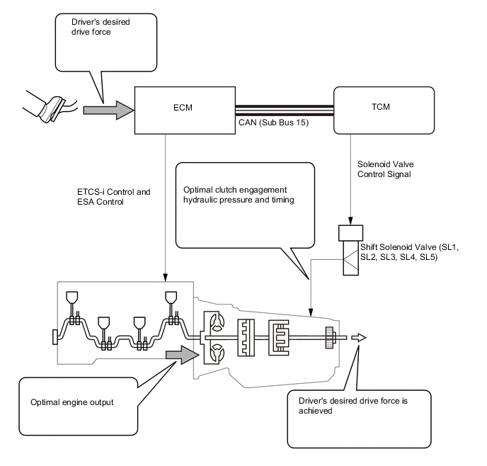
Powertrain Cooperative Control
-
Through cooperative control with ETCS-i (Electronic Throttle Control System-intelligent) and ESA (Electronic Spark Advance), and electronic control of the engagement and release speed of the clutch and brake hydraulic pressures, excellent response and shift shock reduction have been achieved.
-
-
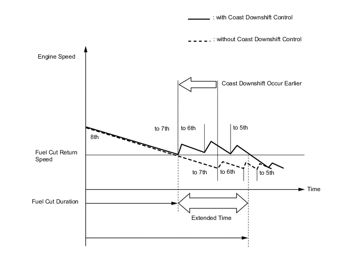
Coast Downshift Control
-
The TCM performs downshift control to prevent the engine speed from decreasing, thus keeping fuel cut control operating for as long as possible. In this way, the fuel economy is improved.
-
In this control, the transmission downshifts from 8th to 7th, 7th to 6th and then 6th to 5th before fuel cut control ends when the vehicle is decelerated in the 8th gear, so that fuel cut control continues operating. In addition, the TCM performs downshifting when the vehicle is decelerated both in the 6th and 7th gears.
-
-
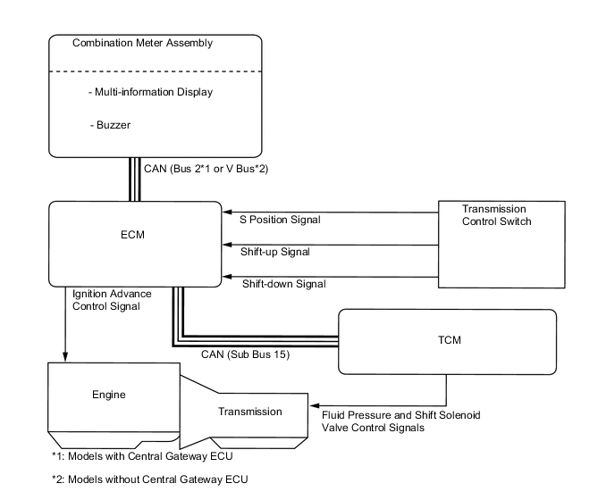
Multi-mode Transmission
-
The driver can select the desired gear range by moving the shift lever to "+" (forward) or "-" (backward) while the shift lever is in S.
-
When the vehicle is being driven at a prescribed speed or higher, any attempt to shift to a lower range by operating the shift lever will not be executed, in order to protect the automatic transmission. In this case, the ECM sounds the buzzer in the combination meter assembly twice to alert the driver.
-
-
Lock-up Timing Control
-
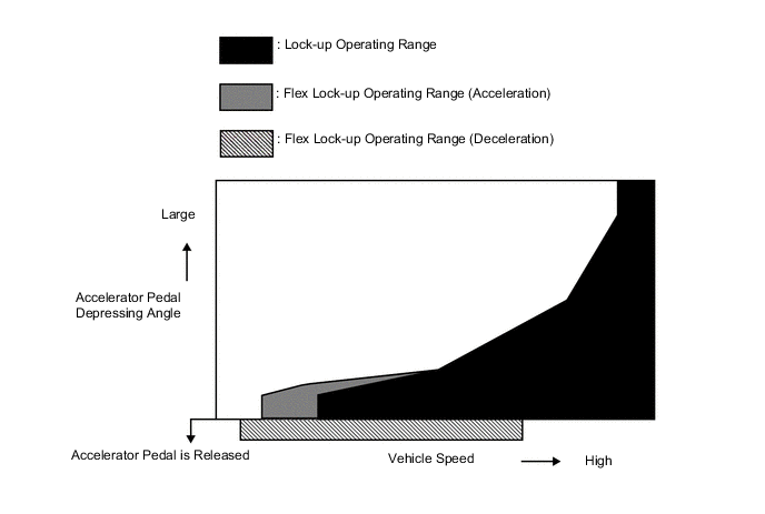
The TCM operates lock-up timing control in order to improve fuel economy performance.
Figure 1. Lock-up Operating Range:
Lock-up Timing Control Operation Gear Shift Position and Shift Range D, S8 S7 S6 S5 1st X X X X 2nd X X X X 3rd X X X X 4th X X X X 5th ○ ○ ○ ○ 6th ○ ○ ○ - 7th ○ ○ - - 8th ○ - - - ○: Operates
X: Does not operate
-: Not applicable
-
-
Flex Lock-up Clutch Control
-
During acceleration, partial control of the power transmission between the lock-up clutch and torque converter greatly boosts transmission efficiency in accordance with the driving conditions, improving fuel economy.
-
Even when the vehicle is decelerating (the accelerator pedal is released), flex lock-up clutch control operates. As a result, the fuel-cut area is expanded and fuel economy is improved.
-
By allowing flex lock-up clutch control to continue operating during gearshifts, smooth torque transmission is obtained. As a result, fuel economy and drivability are improved.
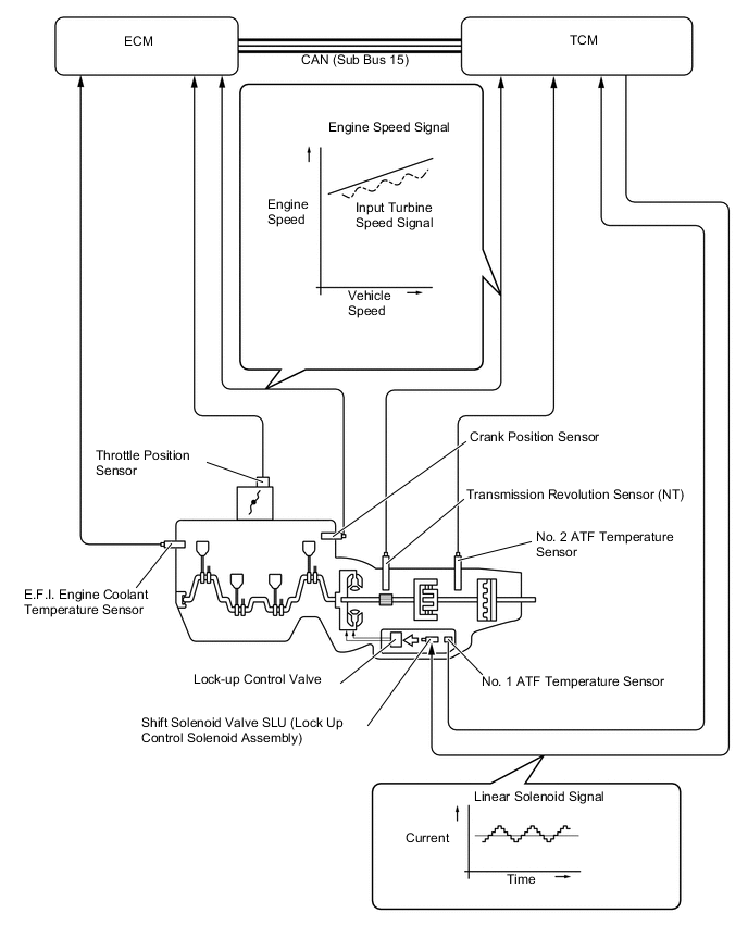
Figure 2. Flex Lock-up Operating Range:
Flex Lock-up Timing Control Operation Gear Shift Position and Shift Range (Fixed Shift Range Mode) D, S8 S7 S6 S5 1st X X X X 2nd X X X X 3rd X X X X 4th X X X X 5th ○ ○ ○ ○ 6th ○ ○ ○ - 7th ○ ○ - - 8th ○ - - - Tech Tips
○: Flex lock-up clutch control operates.
X: Flex lock-up clutch control does not operate.
-: Not applicable gear
-
-
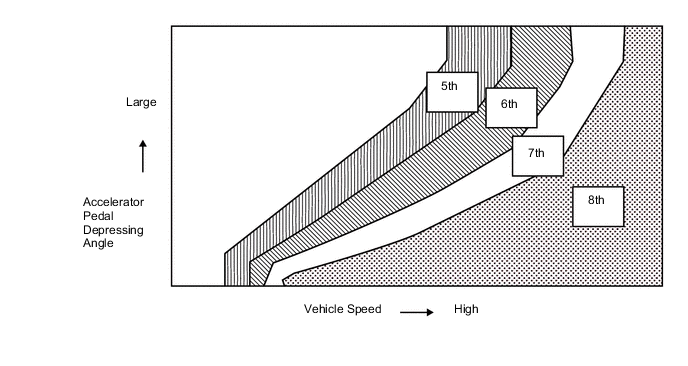
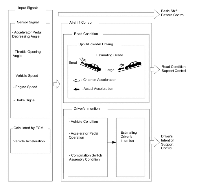
Artificial Intelligence Shift Control (AI-shift Control)
-
AI-shift control determines optimal transmission control based on input signals and automatically changes the shift pattern. As a result, a high caliber of transmission operation is achieved.
-
AI-shift control includes road condition support control and a driver's intention support.
-
AI-shift control is performed with the shift lever in D, based on the accelerator pedal and brake operation data. AI-shift control will be canceled when the shift lever is moved to a position other than D.
-
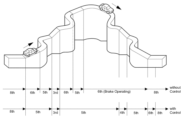
Road Condition Support Control
-
The TCM identifies the throttle valve opening angle, accelerator pedal opening angle and vehicle speed to determine whether the vehicle is being driven uphill or downhill. Unnecessary upshift is restrained to automatically achieve optimal drive force at all times while driving uphill. Downshift is automatically conducted to achieve optimal engine brake force, while driving downhill.
-
-
Driver's Intention Support Control
-
Driver's intention support control is estimated based on the accelerator pedal operation, vehicle condition and a shift pattern that is well-suited to the driver is selected without operating the switch.
-
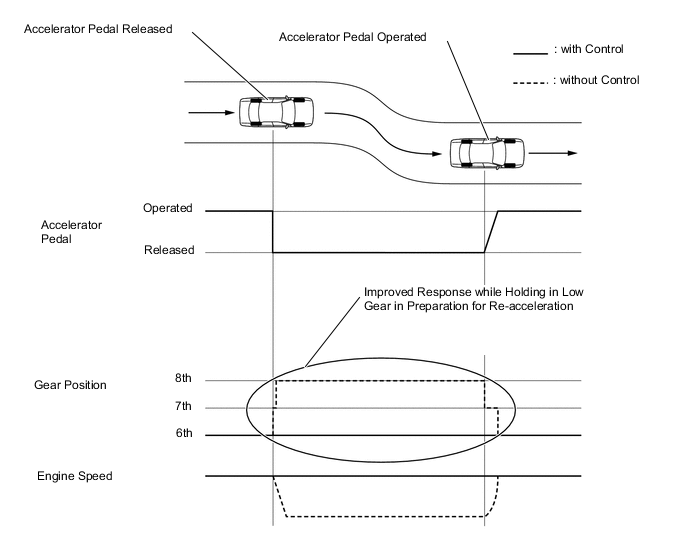
Sudden Accelerator Pedal Release Control
-
When the accelerator pedal is released suddenly, the transmission is kept in gear as long as possible, which improves engine braking force.
-
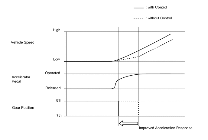
Sudden Accelerator Pedal Depress Control
-
When the accelerator pedal is depressed suddenly, downshifting occurs earlier ensuring improved acceleration response.
-
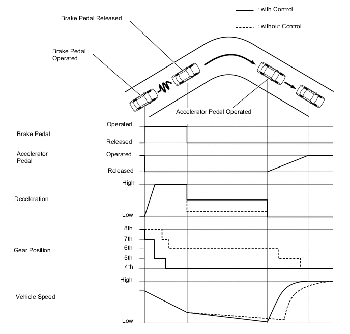
Downshifting Control During Hard Braking
-
High engine braking force and good re-acceleration response have been achieved by actively downshifting during deceleration when hard braking is made.
-
-
-
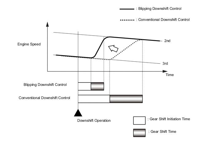
Blipping Downshift Control
-
The blipping downshift control regulates each clutch and brake using the clutch to clutch pressure control, allowing them to be engaged smoothly and disengaged quickly. In addition, fuel injection volume is increased and engine speed is boosted by the powertrain cooperative control, thus ensuring engine brake force. In this way, a smooth and quick downshift is achieved. In addition, further quick down-shifting has been available by directly controlling clutch pressure.
Tech Tips
When the ATF and engine coolant temperature is low, blipping down shift control will not be performed.
-
-
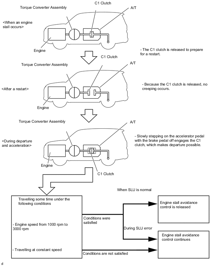
Engine Stall Avoidance Control
-
When an engine stall has occurred, the TCM suspects an ON malfunction of the linear solenoid valve SLU (lock-up control solenoid assembly), and engine stall avoidance control may be engaged by release of the C1 clutch or C3 clutch when the engine is started again. While engine stall avoidance control is engaged, creeping does not occur after the engine is restarted, even when in the D, S, or R shift position.
-
Slowly stepping on the accelerator pedal until the vehicle starts to move with the brake off engages the clutch, which makes departure possible.
-
When the linear solenoid valve SLU (lock-up control solenoid assembly) is normal, running at a constant speed for a short while with the engine speed from 1000 rpm to 3000 rpm releases engine stall avoidance control. The control can also be released by using Techstream and implementing the diagnosis code deletion procedure for the TCM. Furthermore, it is possible to carry out the deletion procedure even without the diagnosis code being entered.
-
When the vehicle departs, and then the linear solenoid valve SLU (lock-up control solenoid assembly) malfunctions or the vehicle stops before the above-mentioned conditions are reached, engine stall avoidance control is not released, so again creeping does not occur.
-
-
-
FUNCTION
-
Drive Mode Select Function
-
The drive mode can be selected by operating the combination switch assembly (Integration Control and Panel Assembly) (ECT POWER mode switch*1, drive mode select switch*2 or ECT 2nd start mode switch).
-
*1: Models with ECT POWER mode switch
-
*2: Models with drive mode select switch
Characteristics of Drive Mode (Models with ECT POWER Mode Switch) Drive Mode Outline NORMAL Mode Best for easy driving. ECT POWER Mode Optimal for sporty driving through the improved acceleration and responsiveness by changing the shifting points of the transmission from those of the NORMAL mode and controlling the throttle positions. ECT 2nd Start Mode Allows the vehicle to start in the 2nd gear for providing an enough traction force at slippery road surfaces such as sands and snow. Characteristics of Drive Mode (Models with Drive Mode Select Switch) Drive Mode Outline NORMAL Mode Best for easy driving. COMFORT Mode ECO Mode Controls the driving force for superior fuel economy property, compared to NORMAL mode, making it possible low fuel consumption drive. SPORT S Mode Optimal for sporty driving through the improved acceleration and responsiveness by changing the shifting points of the transmission from those of the NORMAL mode and controlling the throttle positions. SPORT S+ Mode ECT 2nd Start Mode Allows the vehicle to start in the 2nd gear for providing an enough traction force at slippery road surfaces such as sands and snow. 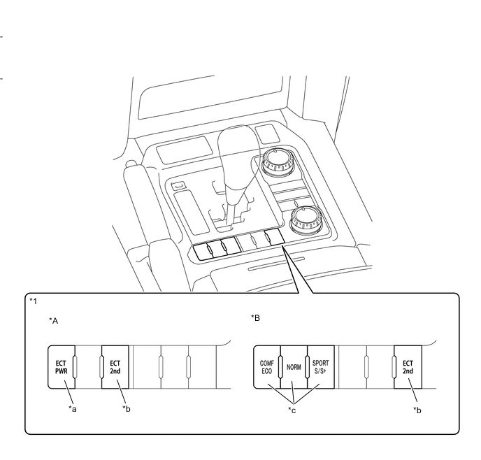
*A Models with ECT POWER Mode Switch *B Models with Drive Mode Select Switch *1 Combination Switch Assembly (Integration Control and Panel Assembly) - - *a ECT POWER Mode Switch *b ECT 2nd Start Mode Switch *c Drive Mode Select Switch - - 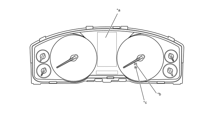
*a Multi-information Display *b ECT POWER Mode Indicator Light *c ECT 2nd Start Mode Indicator Light - - -
-
-
-
CONSTRUCTION
-
ATF Cooler
-
The water cooled oil cooler cools down the ATF using the engine coolant, and is fitted on the lower of the radiator.
-
The air cooled oil cooler cools down the ATF using the cooling fins which are provided on the cooler itself, and is fitted inside the radiator grille so that it can be exposed to the air directly while the vehicle is running.
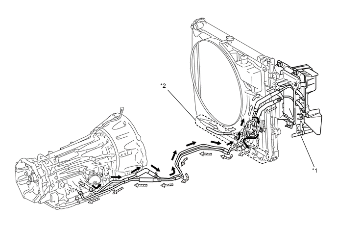
*1 Air Cooled Oil Cooler (Oil Cooler with Hose Assembly) *2 Water Cooled Oil Cooler (Built-in Radiator) 
ATF Flow (to Water Cooled Oil Cooler (Built-in Radiator)) 
ATF Flow (to Air Cooled Oil Cooler (Oil Cooler with Hose Assembly)) 
ATF Flow (from Air Cooled Oil Cooler (Oil Cooler with Hose Assembly)) - -
-
-
Torque Converter
-
A compact, lightweight and high-capacity torque converter assembly is used. The torque converter supports lock-up clutch control, thus improving fuel economy.
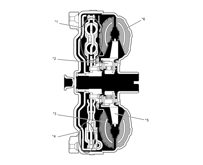
*1 Lock-up Damper *2 1-way Clutch *3 Turbine Runner *4 Lock-up Clutch *5 Stator *6 Pump Impeller
-
-
Oil Pump
-
The oil pump is operated by the torque converter. It lubricates the planetary gear units and supplies operating fluid pressure for hydraulic control. The oil pump drive gear is continually driven by the engine via the pump impeller. The pump has sufficient capacity to supply the necessary fluid pressure throughout all speed ranges, as well as in reverse.
-
The pump cover is made of aluminum to reduce weight.
-
A pump cover with an integrated piston cylinder for the No. 1 brake (B1) is used.
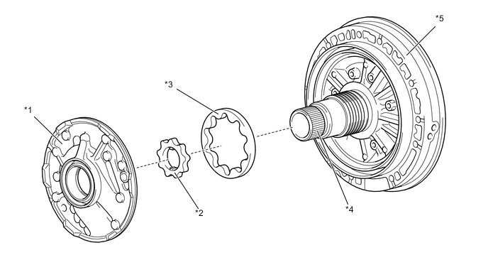
*1 Pump Body *2 Drive Gear *3 Driven Gear *4 Stator Shaft *5 Pump Cover - -
-
-
ATF Filling Procedure
-
An ATF filling procedure is used in order to improve the accuracy of the ATF level when the transmission is being repaired or replaced. As a result, the oil filler tube and the oil level gauge used in a conventional automatic transmission have been discontinued, eliminating the need to inspect the fluid level as a part of routine maintenance. For details about the ATF filling procedures, refer to the Repair Manual.
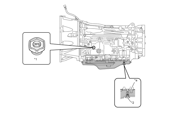
*1 Refill Plug *2 Overflow Plug *a Oil Level - -
-
-
Planetary Gear
-
The gear train consists of 4 multi-plate clutches, 2 multi-plate brakes, a 1-way clutch, and 2 sets of planetary gears each consisting of a sun gear, a pinion gear and a ring gear.
-
Gear noise has been reduced through the optimized gears including the number of teeth, arrangements, and contact surfaces.
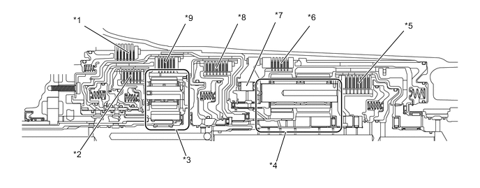
*1 No. 1 Brake (B1) *2 No. 4 Clutch (C4) *3 Front Planetary Gear Unit *4 Rear Planetary Gear Unit *5 No. 2 Clutch (C2) *6 No. 2 Brake (B2) *7 No. 1 1-way Clutch (F1) *8 No. 1 Clutch (C1) *9 No. 3 Clutch (C3) - - 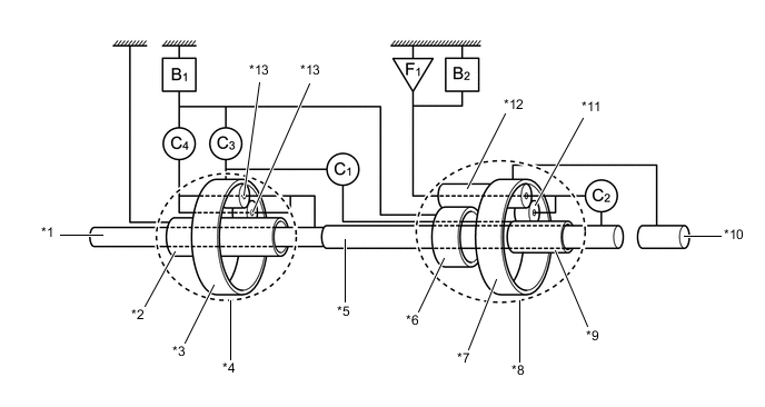
*1 Input Shaft *2 Front Planetary Sun Gear *3 Front Planetary Ring Gear *4 Front Planetary Gear Unit *5 Intermediate Shaft *6 Rear Planetary Middle Sun Gear *7 Rear Planetary Ring Gear *8 Rear Planetary Gear Unit *9 Rear Planetary Rear Sun Gear *10 Output Shaft *11 Rear Planetary Short Pinion Gear *12 Rear Planetary Long Pinion Gear *13 Front Planetary Pinion Gear - - C1
No. 1 Clutch C2
No. 2 Clutch C3
No. 3 Clutch C4
No. 4 Clutch B1
No. 1 Brake B2
No. 2 Brake F1
No. 1 1-way Clutch - -
-
-
Centrifugal Fluid Pressure Canceling Mechanism
-
The clutch engagement force during shift transmission is affected by the centrifugal fluid pressure that acts on the fluid inside the piston fluid pressure chamber (referred to as "chamber A"), in addition to the original clutch pressure regulated by the valve body. In order to eliminate the influence caused by the centrifugal fluid pressure, the canceling fluid pressure chamber (referred to as "chambers") is provided on the opposite side of chamber A to cancel out the centrifugal fluid pressure. As a result, the centrifugal fluid pressure canceling mechanism provides responsive, smooth shift transmission.
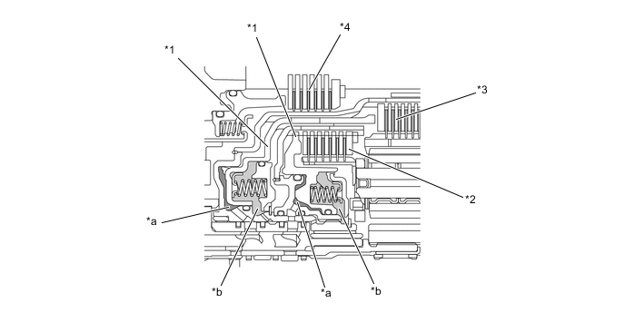
*1 Piston *2 No. 4 Clutch (C4) *3 No. 3 Clutch (C3) *4 No. 1 Brake (B1) *a Chamber A *b Chamber B -
Chamber B is filled by fluid supplied to the shaft for lubrication. As a result of filling chamber B, the same amount of fluid pressure is present on both sides of the piston due to centrifugal force. This cancels the effects of fluid pressure on the piston caused by centrifugal force. Accordingly, it is not necessary to discharge the fluid through the use of a check ball, and highly responsive and smooth shifting characteristics are achieved.
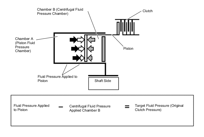
Target fluid pressure Centrifugal fluid pressure applied to chamber A Centrifugal fluid pressure applied to chamber B - -
-
-
Transmission Valve Body
-
The transmission valve body assembly consists of the upper and lower valve bodies and 9 shift solenoid valves.
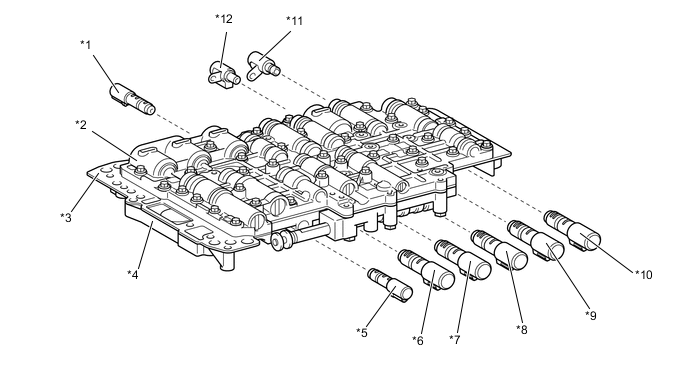
*1 Shift Solenoid Valve SLU (Lock Up Control Solenoid Assembly) *2 Upper Valve Body *3 Plate *4 Lower Valve Body *5 Shift Solenoid Valve SLT (Line Pressure Control Solenoid Assembly) *6 Shift Solenoid Valve SL1 (Shift Control Solenoid Assembly) *7 Shift Solenoid Valve SL4 (Shift Control Solenoid Assembly) *8 Shift Solenoid Valve SL2 (Shift Control Solenoid Assembly) *9 Shift Solenoid Valve SL5 (Shift Control Solenoid Assembly) *10 Shift Solenoid Valve SL3 (Shift Control Solenoid Assembly) *11 Shift Solenoid Valve SC1 (Transmission 3-way Solenoid Assembly) *12 Shift Solenoid Valve SC2 (Transmission 3-way Solenoid Assembly)
-
-
Shift Solenoid Valves SL1, SL2, SL3, SL4 ,SL5 (Shift Control Solenoid Assembly), SLT (Line Pressure Control Solenoid Assembly) and SLU (Lock Up Control Solenoid Assembly)
-
In order to provide a hydraulic pressure that is proportional to the current that flows to the solenoid coil, shift solenoid valves SL1, SL2, SL3, SL4, SL5, SLU and SLT linearly control the line pressure and clutch and brake engagement pressure based on the signals from the TCM.
-
The shift solenoid valves SL1, SL2, SL3, SL4 and SL5 are large flow linear solenoid valves that can supply more pressure than conventional ones. These shift solenoid valves control engagement elements by directly regulating the line pressure without using the pressure regulation valve or the pressure reduction valve. Thus, the number of valves and the length of the valve body fluid passage have been reduced, the shifting response has been improved and the shift shock has been minimized.
Figure 3. Shift Solenoid Valve SL1, SL4 and SL5 (Shift Control Solenoid Assembly)
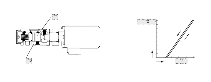
*1 Spool Valve *2 Hydraulic Pressure *3 Sleeve *4 Current Figure 4. Shift Solenoid Valve SL2 and SL3 (Shift Control Solenoid Assembly)
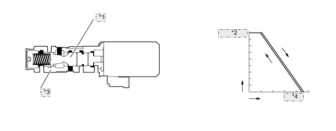
*1 Spool Valve *2 Hydraulic Pressure *3 Sleeve *4 Current Figure 5. Shift Solenoid Valve SLU (Lock Up Control Solenoid Assembly)
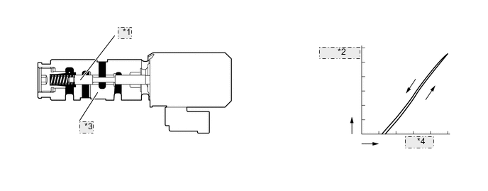
*1 Spool Valve *2 Hydraulic Pressure *3 Sleeve *4 Current Figure 6. Shift Solenoid Valve SLT (Line Pressure Control Solenoid Assembly)
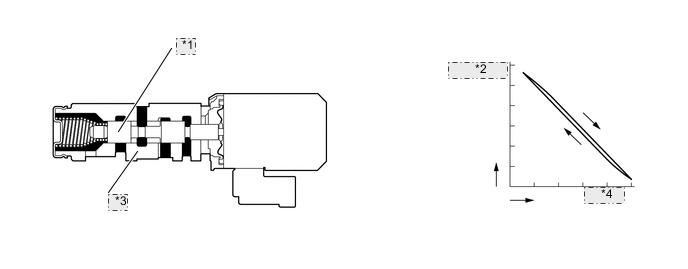
*1 Spool Valve *2 Hydraulic Pressure *3 Sleeve *4 Current
-
-
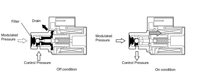
Shift Solenoid Valves SC1 and SC2
-
A 3-way solenoid valve is used for the shift solenoid valves SC1 and SC2.
-
A filter is provided at the tip of the shift solenoid valves to further improve operational reliability.
Figure 7. Shift Solenoid Valve SC1 (Transmission 3-way Solenoid Assembly)
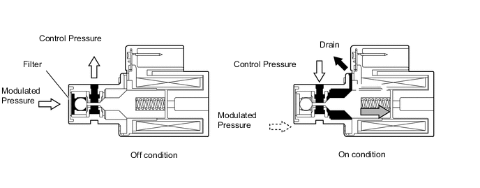
Figure 8. Shift Solenoid Valve SC2 (Transmission 3-way Solenoid Assembly)
-
-
Transmission Revolution Sensor
-
This automatic transmission uses the transmission revolution sensor (NT) and Transmission Revolution Sensor (SP2). Thus, the TCM can detect the timing of the shifting of the gears and appropriately control the engine torque and hydraulic pressure in response to various conditions. These transmission revolution sensors are Hall type.
-
The transmission revolution sensor (NT) detects the input speed of the transmission. The input shaft is used as the timing rotor for this sensor.
-
The Transmission Revolution Sensor (SP2) detects the speed of the output shaft. The rear planetary ring gear is used as the timing rotor for this sensor.
-
The Hall type transmission revolution sensor consists of a magnet and Hall IC. The Hall IC converts the changes in the magnetic flux density that occur through the rotation of the timing rotor into an electric signal, and outputs the signal to the TCM.
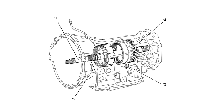
*1 Input Shaft *2 Transmission Revolution Sensor (NT) *3 Transmission Revolution Sensor (SP2) *4 Rear Planetary Ring Gear
-
-
ATF Temperature Sensor
-
The No. 1 ATF temperature sensor is installed in the transmission valve body assembly for direct detection of the fluid temperature.
-
The No. 1 ATF temperature sensor is used for the revision of clutch and brake pressures to maintain a smooth shift quality every time.
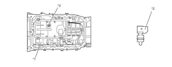
*1 Transmission Valve Body Assembly *2 No. 1 ATF Temperature Sensor -
The No. 2 ATF temperature sensor is measures the temperature of the ATF to the oil cooler.
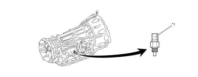
*1 No. 2 ATF Temperature sensor - -
-
-
Park/Neutral Position Switch and Transmission Control Switch
-
The park/neutral position switch assembly sends the C and NSW signals to the ECM.
-
The park/neutral position switch assembly sends the PA, A, B and C signals to the TCM.
-
The transmission control switch is installed inside the transmission floor shift assembly to detect the S mode position and to inform the ECM.
-
The transmission control switch detects whether the shift lever is in D or S, and detects the operating conditions of the shift lever "+" (forward) or "-" (backward) when the shift lever is in S, and sends signals to the ECM.

-
-
-
OPERATION
-
Transmission Power Flow
Operating Condition of Shift Solenoid Valves Shift Position, Shift Range and Gear Range Shift Solenoid Valve SL1 SL2 SL3 SL4 SL5 P X ○ ○ X X R X ○ X X X N X ○ ○ X X D, S8 1st ○ ○ ○ X X 2nd ○ ○ ○ X ○ 3rd ○ ○ X X X 4th ○ ○ ○ ○ X 5th ○ X ○ X X 6th X X ○ ○ X 7th X X X X X 8th X X ○ X ○ S7 1st ○ ○ ○ X X 2nd ○ ○ ○ X ○ 3rd ○ ○ X X X 4th ○ ○ ○ ○ X 5th ○ X ○ X X 6th X X ○ ○ X 7th X X X X X S6 1st ○ ○ ○ X X 2nd ○ ○ ○ X ○ 3rd ○ ○ X X X 4th ○ ○ ○ ○ X 5th ○ X ○ X X 6th X X ○ ○ X S5 1st ○ ○ ○ X X 2nd ○ ○ ○ X ○ 3rd ○ ○ X X X 4th ○ ○ ○ ○ X 5th ○ X ○ X X S4 1st ○ ○ ○ X X 2nd ○ ○ ○ X ○ 3rd ○ ○ X X X 4th ○ ○ ○ ○ X S3 1st ○ ○ ○ X X 2nd ○ ○ ○ X ○ 3rd ○ ○ X X X S2 1st ○ ○ ○ X X 2nd ○ ○ ○ X ○ S1 1st ○ X ○ X X ○: On
●: In Accordance with Flex Lock-up
X: Off
Operating Condition of Shift Solenoid Valves Shift Position, Shift Range and Gear Range Shift Solenoid Valve SC1 SC2 SLU P ○ X X R ○ X X N ○ X X D, S8 1st ○ X X 2nd ○ X X 3rd ○ X ● 4th ○ X ● 5th ○ X ● 6th ○ X ● 7th ○ X ● 8th ○ X ● S7 1st ○ X X 2nd ○ X X 3rd ○ X ● 4th ○ X ● 5th ○ X ● 6th ○ X ● 7th ○ X ● S6 1st ○ X X 2nd ○ X X 3rd ○ X ● 4th ○ X ● 5th ○ X ● 6th ○ X ● S5 1st ○ X X 2nd ○ X X 3rd ○ X ● 4th ○ X ● 5th ○ X ● S4 1st ○ X X 2nd ○ X X 3rd ○ X ● 4th ○ X ● S3 1st ○ X X 2nd ○ X X 3rd ○ X ● S2 1st ○ X X 2nd ○ X X S1 1st X ○ X ○: On
●: In Accordance with Flex Lock-up
X: Off
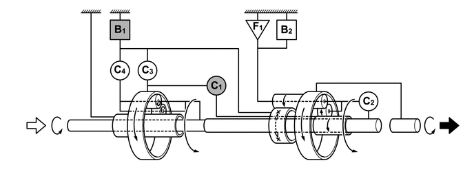
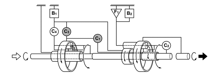
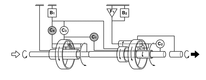
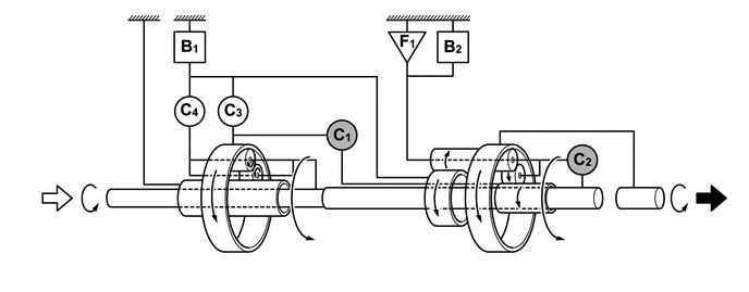
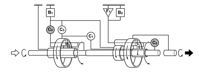
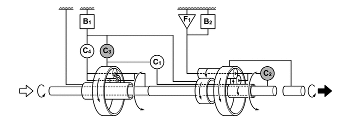
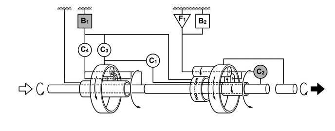
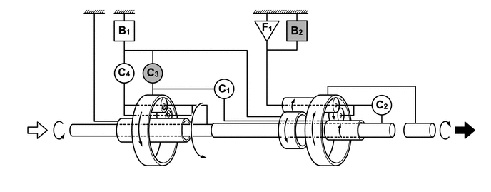
Operating Condition of Friction Engagement Components and 1-way Clutch Shift Position, Shift Range and Gear Range Clutch Brake 1-way Clutch C1 C2 C3 C4 B1 B2 F1 P - - - - - - - R - - ○ - - ○ - N - - - - - - - D, S8 1st ○ - - - - - ○ 2nd ○ - - - ○ - - 3rd ○ - ○ - - - - 4th ○ - - ○ - - - 5th ○ ○ - - - - - 6th - ○ - ○ - - - 7th - ○ ○ - - - - 8th - ○ - - ○ - - S7 1st ○ - - - - - ○ 2nd ○ - - - ○ - - 3rd ○ - ○ - - - - 4th ○ - - ○ - - - 5th ○ ○ - - - - - 6th - ○ - ○ - - - 7th - ○ ○ - - - - S6 1st ○ - - - - - ○ 2nd ○ - - - ○ - - 3rd ○ - ○ - - - - 4th ○ - - ○ - - - 5th ○ ○ - - - - - 6th - ○ - ○ - - - S5 1st ○ - - - - - ○ 2nd ○ - - - ○ - - 3rd ○ - ○ - - - - 4th ○ - - ○ - - - 5th ○ ○ - - - - - S4 1st ○ - - - - - ○ 2nd ○ - - - ○ - - 3rd ○ - ○ - - - - 4th ○ - - ○ - - - S3 1st ○ - - - - - ○ 2nd ○ - - - ○ - - 3rd ○ - ○ - - - - S2 1st ○ - - - - - ○ 2nd ○ - - - ○ - - S1 1st ○ - - - - ○ ○ ○: Operates
-: Does not Operate
Figure 9. 1st Gear (S1)
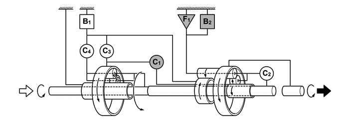
Output Input 
Operates - - Figure 10. 1st Gear (D, S2 to S8)
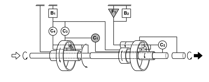
Output Input Operates - - Figure 11. 2nd Gear (D, S)
Output Input Operates - - Figure 12. 3rd Gear (D, S)
Output Input Operates - - Figure 13. 4th Gear (D, S)
Output Input Operates - - Figure 14. 5th Gear (D, S)
Output Input Operates - - Figure 15. 6th Gear (D, S)
Output Input Operates - - Figure 16. 7th Gear (D, S)
Output Input Operates - - Figure 17. 8th Gear (D, S)
Output Input Operates - - Figure 18. Reverse Gear
Output Input Operates - -
-
-
FAIL-SAFE
-
This function minimizes the loss of operability when an abnormality occurs in a sensor or solenoid. For details, refer to the Repair Manual.
-
-
DIAGNOSIS
-
When the TCM detects a malfunction, it stores information related to the malfunction. Furthermore, the TCM illuminates the MIL in the combination meter assembly to inform the driver.
-
The TCM will also store the Diagnostic Trouble Codes (DTCs) of the malfunctions.
-
The DTCs can be read by connecting a Global TechStream (GTS) to the DLC3.
-
For details, refer to the Repair Manual.
-
-
SHIFT CONTROL MECHANISM
-
General
-
A gate type shift lever that uses a transmission control rod is used.
-
The shift control mechanism consists of a transmission floor shift assembly and a floor shift gear shifting rod sub-assembly.
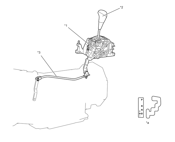
*1 Transmission Floor Shift Assembly *2 Shift Lever Knob Sub-assembly *3 Floor Shift Gear Shifting Rod Sub-assembly - - *a Shift Pattern - -
-
-
SHIFT LOCK SYSTEM
-
The shift lock system prevents the shift lever from being moved to any position other than P, unless the engine switch is turned on (IG) and the brake pedal is depressed. This prevents the vehicle from starting off suddenly.
-
The shift lock system is controlled by the shift lock control ECU, and it has a shift lock function.
-
The shift lock control ECU has a built-in P detection switch to detect the shift lever position, and receives input signals from the stop light switch assembly and engine switch. Upon receiving these signals, the shift lock control ECU turns on the shift lock solenoid assembly in order to release the shift lock.
Figure 19. System Diagram
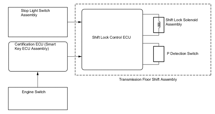
Figure 20. Parts Location
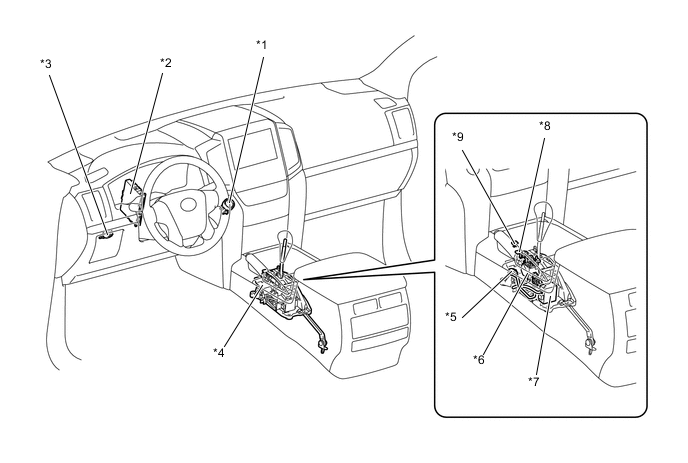
*1 Engine Switch *2 Certification ECU (Smart Key ECU Assembly) *3 Stop Light Switch Assembly *4 Transmission Floor Shift Assembly *5 P Detection Switch *6 Shift Lock Solenoid Assembly *7 Shift Lock Control ECU *8 Shift Lock Release Button *9 Shift Lock Release Button Cap - -
-
-
SHIFT LOCK CONTROL
Function of Main Components Component Function Transmission Floor Shift Assembly Shift Lock Solenoid Assembly Locks the shift lever in P. P Detection Switch Detects when the shift lever is in P. Shift Lock Control ECU Controls the Shift Lock Solenoid assembly and the key interlock solenoid based on signals from each switch. Stop Light Switch Assembly Detects when the brake pedal is depressed. -
SYSTEM CONTROL
-
The shift lock control ECU uses the P detection switch to detect the shift lever position, and receives input signals from the stop light switch assembly and engine switch. Upon receiving these signals, the shift lock control ECU turns on the shift lock solenoid assembly in order to release shift lock.
-
-
FUNCTION
-
Shift Lock Mechanism
-
The shift lock mechanism prevents the shift lever from being moved to any position other than P, unless the engine switch is on (IG), and the brake pedal is depressed. This mechanism helps to prevent unintentional acceleration.
-
A shift lock release button, which manually overrides the shift lock mechanism, is provided.
-
-
-