NEW FEATURES
-
DESCRIPTION
-
General
-
The exterior lights design has been changed.
-
On models with automatic high beam system, the components of the system have been changed.
-
The Light Emitting Diode (LED) is used to the light source for interior lights depending on models.
-
Depending on models, the door trim illumination is newly provided.
-
The lighting system includes the following equipment:
Item Equipment Headlight (LED*1 or Halogen) Standard Front Fog Light (LED*1) Standard/Option or Not Equipped Daytime Running Light System Standard or Not Equipped Illuminated Entry System Standard Automatic Light Control System Standard/Option or Not Equipped Light Turn-OFF System (With Delay Function*2) Standard Automatic or Manual Headlight Beam Level Control System Standard or Not Equipped Automatic High Beam System Standard/Option or Not Equipped Headlight Cleaner System Standard/Option or Not Equipped *1: Light Emitting Diode
*2: Models for Europe
-
-
Front Exterior Light
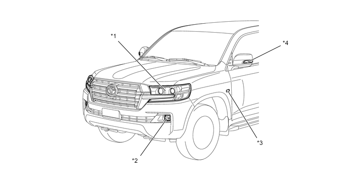
*1 Headlight Assembly *2 Front Fog Light (Models with Front Fog Light) *3 Side Turn Signal Light (on Front Fender Type) *4 Side Turn Signal Light (on Outer Rear View Mirror Type)
-
Halogen Headlight Light Assembly
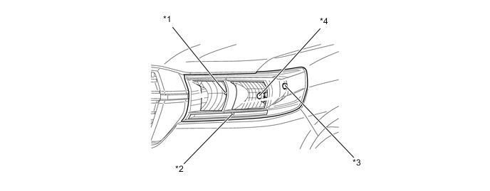
*1 High Beam Headlight *2 Clearance Light *3 Front Turn Signal Light *4 Low Beam Headlight Specifications Light Type Headlight Assembly High Beam Headlight 60 W: HB3 Type Low Beam Headlight 51 W: HB4 Type Front Turn Signal Light Wedge Base Bulb (Amber) 21 W : WY21W Clearance Light Wedge Base Bulb 5 W : W5W -
LED Headlight Assembly (High Beam Halogen Type)
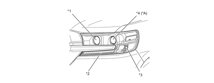
*A Models with bi-beam function - - *1 High Beam Headlight *2 Clearance Light / Daytime Running Light *3 Front Turn Signal Light *4 Low Beam Headlight / High Beam Headlight Specifications Light Type Headlight Assembly High Beam Headlight Projector Type (Halogen) 60 W : HB3 Low Beam Headlight / High Beam Headlight* Projector Type (LED) 29 W / 34 W* Front Turn Signal Light Wedge Base Bulb (Amber) 21 W : WY21W Clearance Light / Daytime Running Light LED 0.5 W / 7.5 W *: Models with bi-beam function
-
LED Headlight Light Assembly (High Beam LED Type)
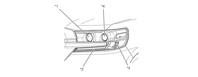
*1 High Beam Headlight *2 Clearance Light / Daytime Running Light *3 Front Turn Signal Light *4 Low Beam Headlight / High Beam Headlight Specifications Light Type Headlight Assembly High Beam Headlight Projector Type (LED) 23 W Low Beam Headlight / High Beam Headlight Projector Type (LED) 29 W / 34 W Front Turn Signal Light Wedge Base Bulb (Amber) 21 W : WY21W Clearance Light / Daytime Running Light LED 0.5 W / 7.5 W -
Side Turn Signal Light and Front Fog Light
Specifications Light Type Side Turn Signal Light (on Outer Rear View Mirror Type) LED 0.4 W Side Turn Signal Light (on Front Fender Type) Wedge Base Bulb (Amber) 5 W : WY5W Front Fog Light Multi-Reflector Type (LED) 5.9 W
-
-
Rear Exterior Light (Lift Up Type Back Door)
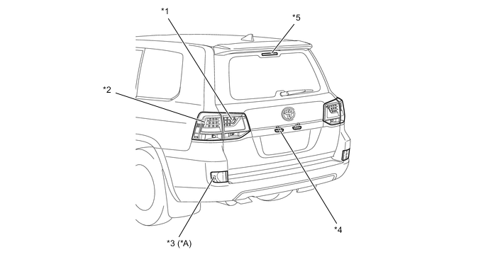
*A Models with Rear Fog Light - - *1 Rear Light Assembly *2 Rear Combination Light Assembly *3 Rear Fog Light *4 License Plate Lights *5 Center Stop Light - -
-
Rear Combination Light Assembly / Rear Light Assembly
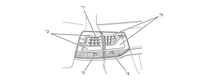
*1 Stop Light *2 Taillight / Stop Light *3 Rear Turn Signal Light *4 Back-up Light *5 Taillight / Stop Light - - Specifications Light Type Rear Combination Light Assembly Taillight / Stop Light LED 1.2 W*1
2.6 W*2
Stop Light Rear Turn Signal Light Wedge Base Bulb (Amber) 21 W : WY21W Rear Light Assembly Taillight / Stop Light LED 1.2 W / 1.3 W Back-up Light Wedge Base Bulb (Clear) 16 W : W16W License Plate Lights Wedge Base Bulb (Clear) 5 W : W5W Center Stop Light LED 1.0 W : 1.8W Rear Fog Light*3 Wedge Base Bulb (Clear) 21 W : W21W *1: When taillights are illuminated.
*2: When stop lights are illuminated.
*3: Models with rear fog light
-
-
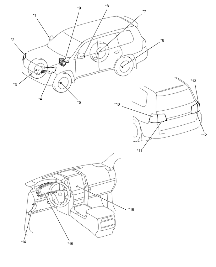
Interior Light (LED Type Interior Light)
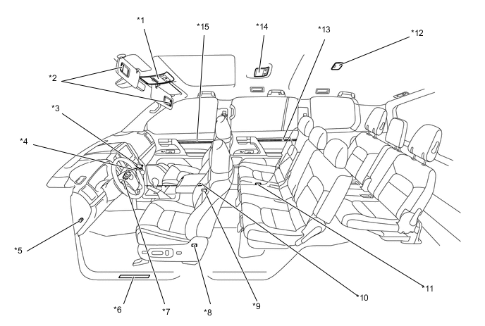
*1 Roof Console Box Assembly *2 Vanity Light *3 Glove Box Light *4 Front Passenger Side Footwell Light *5 Driver Side Footwell Light *6 Scuff Plate Light *7 Engine Switch Illumination *8 Rear Passenger LH Side Footwell Light *9 Rear Passenger RH Side Footwell Light *10 Front Door Courtesy Light *11 Rear Door Courtesy Light *12 No. 2 Room Light *13 Rear Door Trim Illumination *14 No. 1 Room Light *15 Front Door Trim Illumination - - Specifications Light* Type Roof Console Box Assembly Front Interior Light LED Wedge Base Bulb(12V 8W) Map Light No. 1 Room Light LED Wedge Base Bulb(12V 8W) No. 2 Room Light LED Wedge Base Bulb(12V 8W) Vanity Light Double End Bulb: 12 V 2 W Glove Box Light LED Footwell Light LED Scuff Plate Light LED Engine Switch Illumination LED Door Courtesy Light LED Wedge Base Bulb(12V 5W) Door Trim Illumination LED *: The equipments of light differ by vehicle specification.
-
-
LED HEADLIGHT SYSTEM
-
General
-
The Light Emitting Diode (LED) headlight system is used.
-
The LED headlight system uses LEDs as its light source. This system consists of LEDs and LED driver module.
-
The fail-safe function is provided in case that problem occurs in the headlight system.
-
-
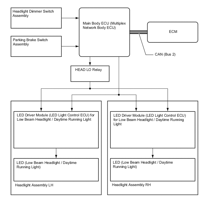
System Diagram
-
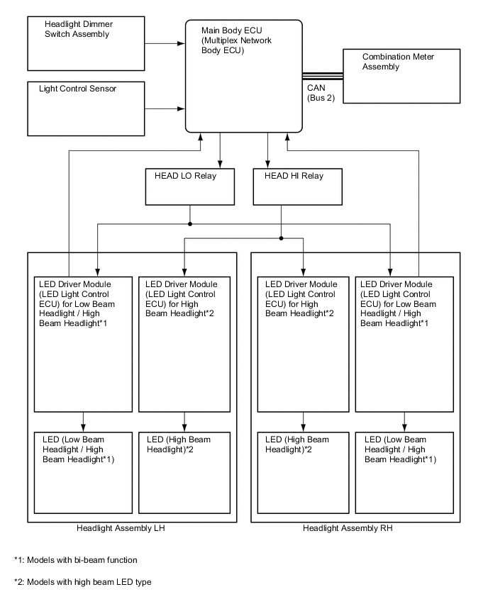
Layout of Main Components
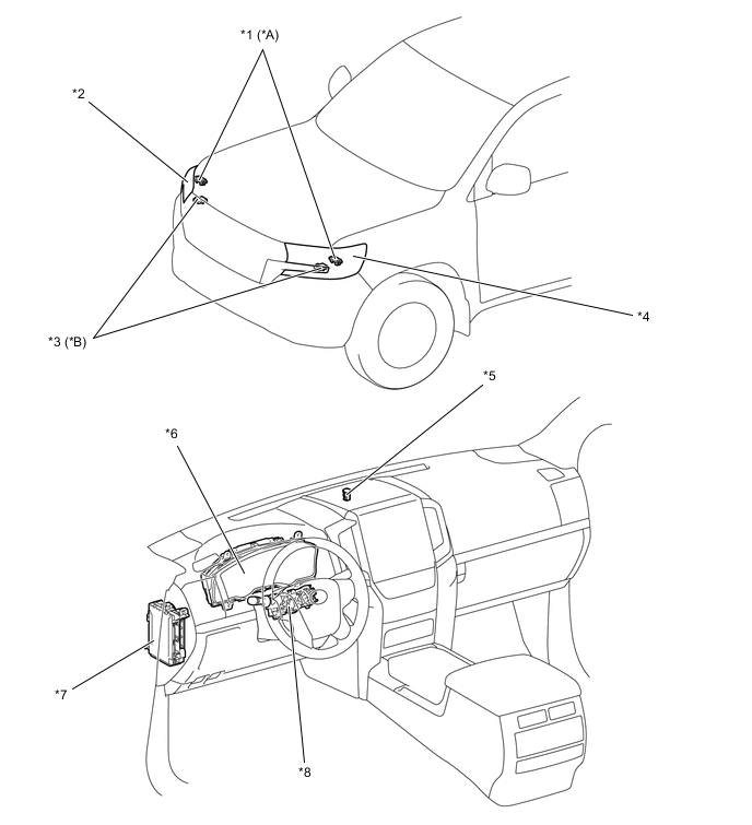
*A Models with bi-beam function *B Models with high beam LED type *1 LED Driver Module (LED Light Control ECU) for Low Beam Headlight / High Beam Headlight *2 Headlight Assembly RH *3 LED Driver Module (LED Light Control ECU) for High Beam Headlight *4 Headlight Assembly LH *5 Light Control Sensor *6 Combination Meter Assembly *7 Main Body ECU (Multiplex Network Body ECU) *8 Headlight Dimmer Switch Assembly -
Construction and Operation
-
LED Driver Module
-
The LED driver module assemblies (LED light control ECU) illuminate the LED used as a light source for the low beam headlights/high beam headlights and high beam headlights.
-
When the low beam headlights/high beam headlights or high beam headlights are illuminated, a constant current flows to the LED to instantly stabilize the headlights. Also, changes in the LED current due to fluctuations in the voltage are reduced to prevent the lights from flickering.
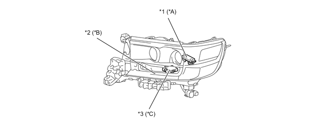
*A Models with bi-beam function *B Models with LED Headlight Light Assembly *C Models with high beam LED type - - *1 LED Driver Module (LED Light Control ECU) for Low Beam Headlight / High Beam Headlight *2 LED Driver Module (Print Base Assembly) for Clearance Light / Daytime Running Light *3 LED Driver Module (LED Light Control ECU) for High Beam Headlight - -
-
-
Headlight Assembly
-
Through optimization of the shape of the lenses and reflectors inside the lights, a large illumination range has been achieved.
Figure 1. Models with High Beam Halogen Type
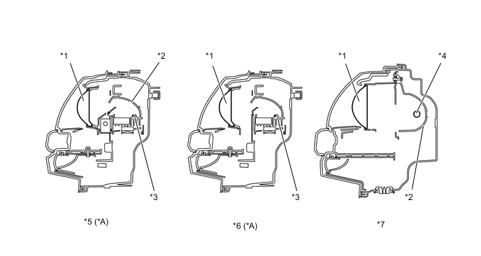
*A Models with Bi-beam Function - - *1 Lens *2 Reflector *3 LED *4 Bulb *5 Low Beam Headlight / High Beam Headlight *6 Low Beam Headlight *7 High Beam Headlight - - Figure 2. Models with High Beam LED Type
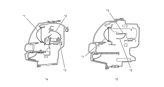
*1 Lens *2 Reflector *3 LED *4 Low Beam Headlight / High Beam Headlight *5 High Beam Headlight - -
-
-
-
-
AUTOMATIC HEADLIGHT BEAM LEVEL CONTROL SYSTEM
-
General
-
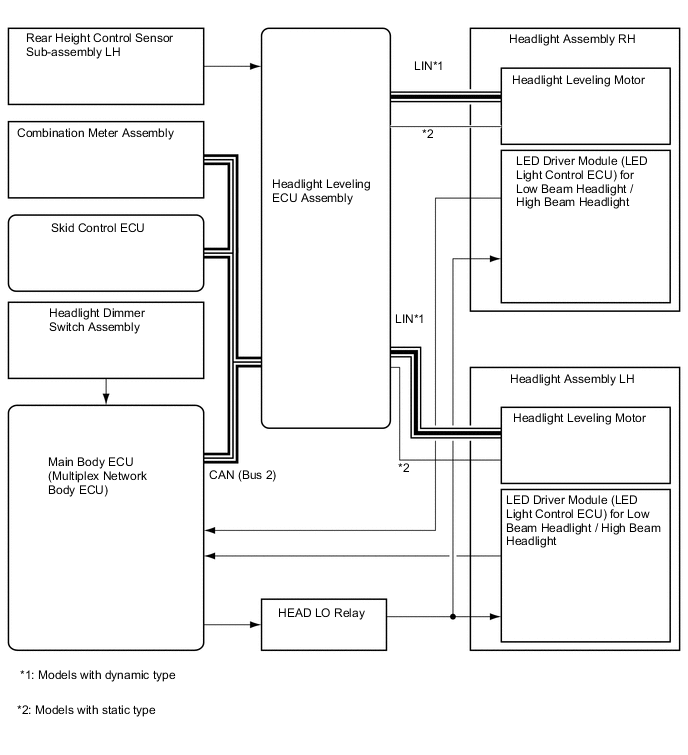
On models with dynamic type automatic headlight beam level control system, when the headlights on, the automatic headlight beam level control system operates the headlight leveling motors in accordance with the movement of the vehicle.
-
On models with static type automatic headlight beam level control system, when the vehicle is stopped with the engine and headlights on, the automatic headlight beam level control system operates the headlight leveling motors in accordance with movement of the vehicle.
-
The headlight leveling ECU assembly receives vehicle height change signals sent from the rear height control sensor sub-assembly LH and calculates the changes in the pitch angle of the vehicle.
-
The headlight leveling ECU assembly drives the headlight leveling motor LH and RH in accordance with the change.
-
-
System Diagram
-
Layout of Main Components
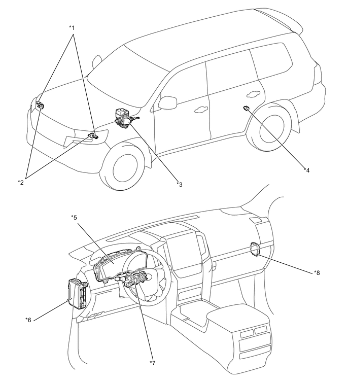
*1 LED Driver Module (LED Light Control ECU) for Low Beam Headlight / High Beam Headlight *2 Headlight Leveling Motor *3 Skid Control ECU *4 Rear Height Control Sensor Sub-assembly LH *5 Combination Meter Assembly *6 Main Body ECU (Multiplex Network Body ECU) *7 Headlight Dimmer Switch Assembly *8 Headlight Leveling ECU Assembly -
Function of Main Components
Component Function LED Driver Module (LED Light Control ECU) Turns the headlights on and off. Headlight Leveling ECU Assembly Receives signals from each ECU and sensor and controls the automatic headlight beam level control system. Headlight Leveling Motor LH and RH Moves the low beam headlights vertically and controls the beam axis direction according to control signals from the headlight leveling ECU assembly. Skid Control ECU Transmits the vehicle speed signal to the headlight leveling ECU assembly. Rear Height Control Sensor Sub-assembly LH Detects the vehicle movement and transmits a signal to the headlight leveling ECU assembly. Headlight Dimmer Switch Assembly Transmits a light control signal to the main body ECU. Main Body ECU (Multiplex Network Body ECU) Receives a light control signal and transmits it to the headlight leveling ECU assembly. Combination Meter Assembly Displays a warning message on the multi-information display and sounds the buzzer to inform the driver when the headlight leveling ECU assembly detects a malfunction in this system. -
Function
-
The headlight leveling ECU assembly calculates changes in the vehicle posture based on the signals from the rear height control sensor sub-assembly LH.
-
Following this, the ECU controls the headlight leveling motors based on this information, in order to change the headlight unit angle.
-
-
Fail-safe
-
If the headlight leveling ECU assembly detects a malfunction in the automatic headlight beam level control system, the headlight leveling ECU assembly performs the fail-safe operation. For details, refer to the Repair Manual.
-
-
-
AUTOMATIC HIGH BEAM SYSTEM
-
General
-
The automatic high beam system is provided.
-
The automatic high beam system detects lights in front of the vehicle and automatically changes between high beams and low beams to support the driver during night driving.
-
-
Precaution of Automatic High Beam System
-
The automatic high beam system is a system that helps ensure visibility by automatically turning the high beams on and off.
-
However, due to control limitations of the automatic high beam system, it may be necessary to manually turn the high beams on and off. When driving, for safety reasons, make sure to change the high beams and low beams manually according to the driving conditions.
-
Under the following conditions, the automatic high beam system might not detect other vehicles or lights correctly, or the high beams might cause glare or flash pedestrians or the occupants of other vehicles. Manual operation should be used.
Factor Condition Weather/Climate When driving in bad weather (rain, snow, fog, sandstorms, etc.). Windshield Glass
-
When the windshield glass is not clear (ice, snow or frost on the glass).
-
When the windshield glass is dirty (sand, mud, water stains or bugs on the glass).
-
When the windshield glass is cracked.
-
When the windshield glass is fogged-up.
-
When the windshield glass has a film attached.
-
When an object on the instrument panel reflects off of the windshield glass.
-
When any other abnormal conditions exist with the windshield glass.
Forward Recognition Camera
-
When a parking tag, magnifying lens or other accessory is mounted on the inner rear view mirror assembly.
-
When the forward recognition camera is deformed.
-
When the forward recognition camera lens is dirty.
-
When any other abnormal conditions exist with the forward recognition camera.
Nearby Vehicles or Lights
-
When lights similar to headlights or taillights are in the vicinity of the vehicle.
-
When a nearby vehicle has no lights or its lights are off.
-
When a vehicle in front has misaligned lights or its lights are changing color.
-
When a vehicle in front has extremely dirty headlights or taillights.
Road Conditions
-
When driving in an area where the conditions often change between bright and dark.
-
When driving on a road with many uphill and downhill slopes.
-
When driving on a winding road or around a sharp curve.
-
When driving on a bumpy road (cobblestone pavement, gravel road, rough unpaved road, etc.).
-
When highly reflective objects are in front of the vehicle (mirrors, road signs, etc.).
Vehicle Conditions
-
When the headlights are damaged, deformed or dirty.
-
When the vehicle posture is abnormal due to flat tire (or posture has changed due to the vehicle being fully loaded, a trailer being towed, road conditions etc.).
-
When the vehicle has other malfunctions or if the vehicle has been modified.
Automatic High Beam System Malfunction:
-
When the automatic high beam indicator light on the combination meter is blinking.
Others:
-
When the automatic high beam system does not seem to be changing between the high beams and low beams properly.
-
When the automatic high beam system is frequently changing between the high beams and low beams.
-
When the glare from the high beams would disturb pedestrians or the drivers of other vehicles.
-
-
-
System Diagram
-
Layout of Main Components
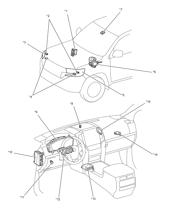
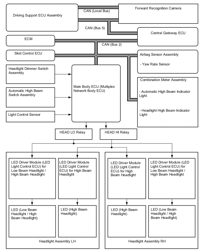
*1 ECM *2 LED Driver Module (LED Light Control ECU) for Low Beam Headlight / High Beam Headlight *3 Headlight Assembly RH *4 LED Driver Module (LED Light Control ECU) for High Beam Headlight *5 Headlight Assembly LH *6 Skid Control ECU *7 Forward Recognition Camera *8 Light Control Sensor *9 Combination Meter Assembly *10 Main Body ECU (Multiplex Network Body ECU) *11 Automatic High Beam Switch Assembly *12 Headlight Dimmer Switch Assembly *13 Airbag Sensor Assembly *14 Central Gateway ECU *15 Driving Support ECU Assembly - - -
Function of Main Components
Component Function Forward Recognition Camera The forward recognition camera determines when to turn the high beams on and off after identifying the lights of oncoming vehicles, preceding vehicles and other lights from the picture information of its camera sensor. Then, it sends high beam request signals to the main body ECU. Airbag Sensor Assembly Yaw Rate Sensor Detects the yaw rate of the vehicle and transmits the signal to the forward recognition camera. Skid Control ECU The skid control ECU outputs information about the vehicle speed. This information is used by the forward recognition camera to control switching between the high and low beams of the automatic high beam system. ECM The ECM outputs a signal to indicate that the shift lever is in R. Based on this signal, the forward recognition camera determines the direction of vehicle movement. Combination Meter Assembly Automatic High Beam Indicator Light The automatic high beam indicator light illuminates to inform the driver when the automatic high beam system is activated. Headlight High Beam Indicator Light The headlight high beam indicator light illuminates to inform the driver when the high beam headlights are on. Main Body ECU (Multiplex Network Body ECU)
-
The main body ECU receives the signals from the automatic high beam switch assembly, headlight dimmer switch assembly and the light control sensor.
-
The main body ECU operates the high beams based on request signals that are received from the forward recognition camera.
-
The main body ECU transmits the signals to the combination meter assembly.
Headlight Dimmer Switch Assembly The headlight dimmer switch assembly transmits the auto position signal and the high beam position signal to the main body ECU. Automatic High Beam Switch Assembly The automatic high beam switch assembly turns on/off the power to the automatic high beam system. Light Control Sensor The light control sensor detects the ambient light level and transmits it to the main body ECU. -
-
Construction
-
Forward Recognition Camera
-
The forward recognition camera consists of the Complementary Metal Oxide Semiconductor (CMOS) that receives images and the mirror portion that identifies light sources, and judges whether to turn high beam headlights on or off.
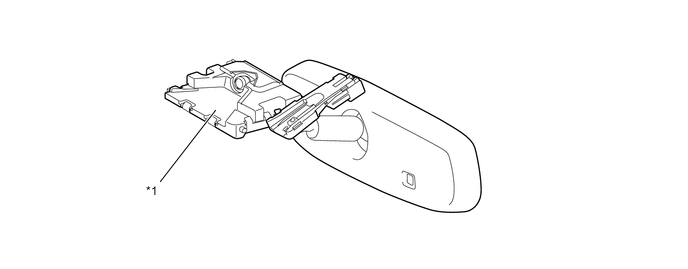
*1 Forward Recognition Camera - -
-
-
Operating Condition
-
The automatic high beam system will operate as follows:
Item Operating Condition System Activation When all of the following conditions are met, the automatic high beam system is activated and the automatic high beam indicator light turns on:
-
The engine switch is on (IG).
-
Automatic high beam system is activated (Automatic high beam switch is not operated).
-
The headlight dimmer switch assembly is in the auto position and high beam position.
-
The light control sensor outputs the night mode signal (to turn the headlights on).
High Beam Headlight On When all of the following conditions are met, the automatic high beam system turns on the high beam headlights after a short delay:
-
Vehicle speed is more than approximately 34 km/h (21 mph).
-
The area in front of the vehicle is dark.
-
No oncoming vehicles are present with the headlights on.
-
No preceding vehicles are present with the taillights on.
-
Few streetlights are present along the street ahead.
High Beam Headlight Off When any of the following conditions are met, the automatic system turns off the high beam headlights after a short delay:
-
Vehicle speed is less than approximately 27 km/h (17 mph).
-
The area in front of the vehicle is not dark.
-
An oncoming vehicle with headlights on is detected.
-
A preceding vehicle with taillights on is detected.
-
Several streetlights are present along the street ahead.
-
-
-
-
Operation
-
When passing an oncoming vehicle
-
The automatic high beam system turns the high beam headlights off when there is an oncoming vehicle before its distance reaches approximately 800 m (2625 ft).
-
When an oncoming vehicle passes the forward recognition camera range, the automatic high beam system turns the high beam headlights on after a short delay.
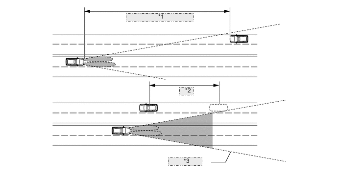
*1 Approx. 800 m (2625 ft.) *2 Delay *3 Camera Angle
Tech Tips
-
The detection distance varies depending on detected objects.
-
Depending on the intensity of oncoming (and preceding) vehicle lights, the timing of turning the high beam headlights on and off will vary.
-
-
When passing a preceding vehicle
-
The automatic high beam system turns the high beam headlights off when there is a preceding vehicle before its distance reaches approximately 600 m (1969 ft).
-
When a preceding vehicle passes the forward recognition camera range, the automatic high beam system turns the high beam headlights on after a short delay.
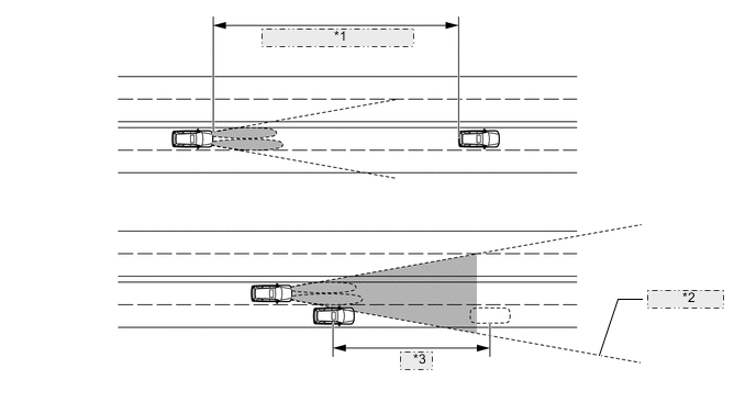
*1 Approx. 600 m (1969 ft.) *2 Camera Angle *3 Delay
Tech Tips
Depending on the intensity of preceding vehicle lights, the timing of turning the high beam headlights on and off will vary.
-
-
-
Diagnosis
-
When the headlight leveling ECU assembly or main body ECU (Multiplex Network Body ECU) detects a malfunction in the automatic high beam control system, a Diagnostic Trouble Code (DTC) is stored in memory. For details, refer to the Repair Manual.
-
-
-
EMERGENCY BRAKE SIGNAL SYSTEM
-
General
-
A hazard warning signal light type emergency brake signal system is used.
-
This function automatically flashes the hazard warning lights during sudden braking, in order to alert vehicles behind and reduce the risk of an accident.
-
-
System Diagram
-
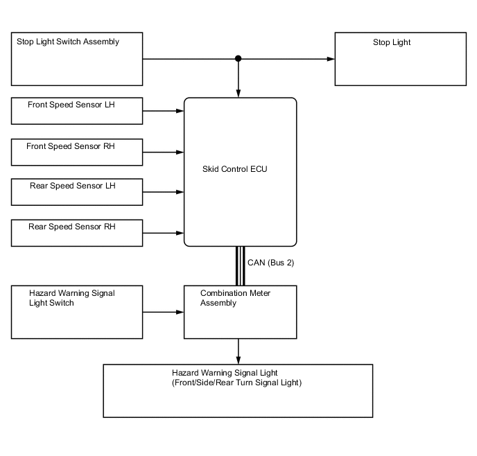
Layout of Main Components
*1 Side Turn Signal Light Assembly RH *2 Headlight Assembly RH
-
Front Turn Signal Light
*3 Front Speed Sensor RH *4 Headlight Assembly LH
-
Front Turn Signal Light
*5 Front Speed Sensor LH *6 Rear Speed Sensor LH *7 Rear Speed Sensor RH *8 Side Turn Signal Light Assembly LH *9 Skid Control ECU *10 Rear Combination Light Assembly LH
-
Stop Light
-
Rear Turn Signal Light
*11 Rear Light Assembly LH
-
Stop Light
*12 Rear Light Assembly RH
-
Stop Light
*13 Rear Combination Light Assembly RH
-
Stop Light
-
Rear Turn Signal Light
*14 Stop Light Switch Assembly *15 Combination Meter Assembly *16 Hazard Warning Signal Light Switch -
-
Function of Main Components
Component Function Skid Control ECU Manages signals from each sensor and requests the emergency brake signal operation signal from the combination meter assembly. Speed Sensors Detects the wheel speed of each of the 4 wheels. Stop Light Switch Assembly Detects the brake pedal depressing signal. Hazard Warning Signal Light Switch Sends the operation signal of the hazard warning signal light switch to the combination meter assembly. Hazard Warning Light Blinks when a signal is received from the combination meter assembly. Headlight Assembly Hazard warning signal light blinks when a signal is received from the combination meter assembly. Side Turn Signal Light Assembly Rear Combination Light Assembly Combination Meter Assembly
-
Received the emergency brake signal light operation signal from the skid control ECU and blinks the hazard warning lights at 3.5 Hz.
-
Received the hazard warning brake signal light operation signal from the hazard warning signal light switch assembly and blinks the hazard warning lights at 1.5 Hz.
-
-
Operation
-
Emergency Brake Signal Control
-
The operating and ending conditions for the emergency brake signal are listed below.
-
When the emergency brake signal operates, the combination meter assembly blinks the hazard warning lights. When the emergency brake signal ends, the combination meter assembly ends the blinking of the hazard warning lights.
-
-
Emergency Brake Signal Operating Condition
-
Activates when all of the following conditions are satisfied:
-
The vehicle speed is 55 km/h (34 mph) or more.
-
The system judges from a depression of the brake pedal and a drop in vehicle speed that emergency braking is occurring.
-
-
Emergency Brake Signal Ending Condition
-
Stops the operation when any of the following conditions is met:
-
The system judges from the vehicle's deceleration that no emergency braking is occurring.
-
The hazard warning signal light switch is on and the hazard warning signal lights are blinking.
-
The brake pedal is released.
-
-
-
-
DAYTIME RUNNING LIGHT SYSTEM
-
General
-
The daytime running light system is designed to automatically illuminate the headlights and allow them to be adjusted during the daytime to keep the car more visible to other vehicles.
-
The main body ECU controls this system.
-
This system is enabled when the conditions given below are met:
-
Engine Switch: ON (IG)
-
Engine Speed Signal Input
-
Light Control Switch AUTO position (if headlight-on control is not being performed by the automatic light control system.)
-
Parking Brake Switch: OFF
-
-
-
System Diagram
-
-
ILLUMINATED ENTRY SYSTEM
-
General
-
The illuminated entry system is used.
-
The door trim illumination has been newly provided.
-
The front interior light, No. 1 room light and No. 2 room light are operated when the light switch is in the DOOR position.
-
The illuminated entry system controls the front foot lights, door trim illuminations and step lights.
-
-
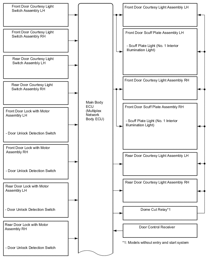
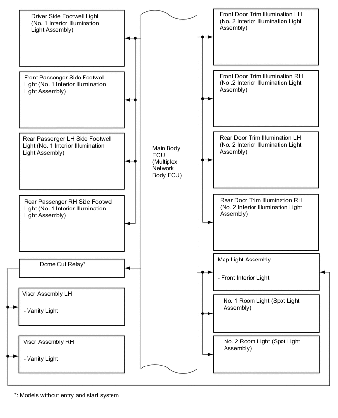
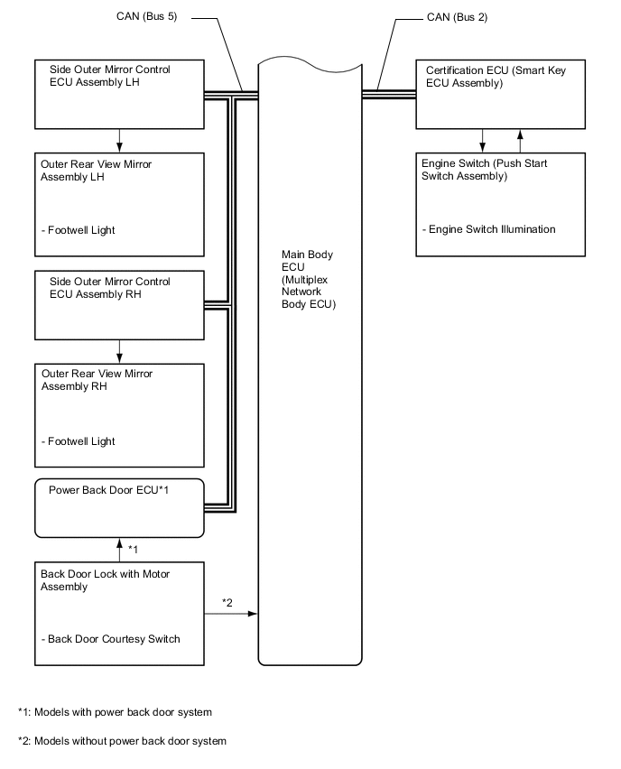
System Diagram
-
Layout of Main Components
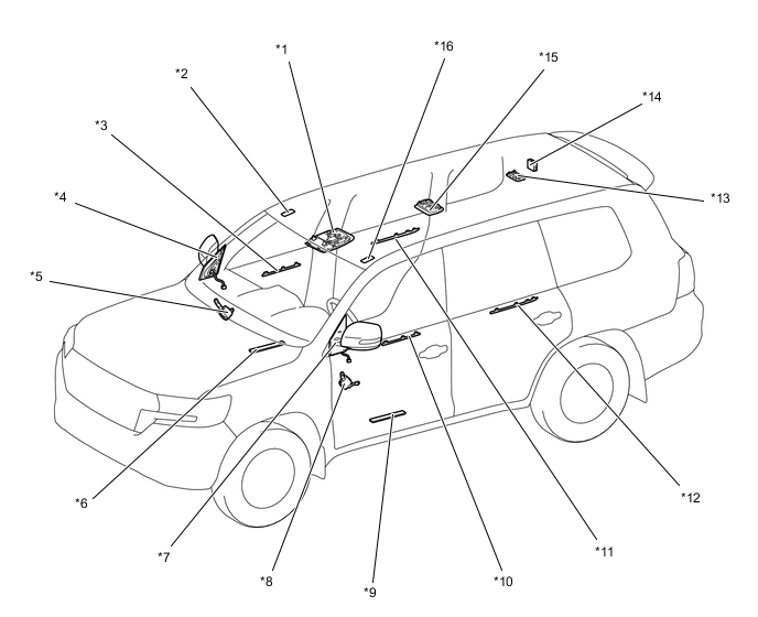
*1 Roof Console Box Assembly *2 Visor Assembly RH (Vanity Light) *3 Front Door Trim Illumination RH *4 Outer Rear View Mirror Assembly RH
-
Footwell Light
*5 Side Outer Mirror Control ECU Assembly RH *6 Front Door Scuff Plate Assembly RH (Scuff Plate Light) *7 Outer Rear View Mirror Assembly LH
-
Footwell Light
*8 Side Outer Mirror Control ECU Assembly LH *9 Front Door Scuff Plate Assembly LH (Scuff Plate Light) *10 Front Door Trim Illumination LH *11 Rear Door Trim Illumination RH *12 Rear Door Trim Illumination LH *13 No. 2 Room Light *14 Door Control Receiver *15 No. 1 Room Light *16 Visor Assembly LH (Vanity Light) 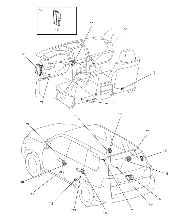
*1 Smart Key ECU Assembly *2 Main Body ECU (Multiplex Network Body ECU) *3 Driver Side Footwell Light *4 Rear Passenger LH Side Footwell Light *5 Rear Passenger RH Side Footwell Light *6 Front Passenger Side Footwell Light *7 Engine Switch *8 Front Door Courtesy Light Switch Assembly RH *9 Front Door Lock with Motor Assembly LH *10 Front Door Courtesy Light Switch Assembly LH *11 Front Door Courtesy Light Assembly LH *12 Rear Door Courtesy Light Assembly LH *13 Rear Door Lock with Motor Assembly LH *14 Rear Door Courtesy Light Switch Assembly LH *15 Front Door Courtesy Light Assembly RH *16 Rear Door Courtesy Light Assembly RH *17 Back Door Lock with Motor Assembly *18 Rear Door Courtesy Light Switch Assembly RH *19 Power Back Door ECU *20 Rear Door Lock with Motor Assembly RH *21 Front Door Lock with Motor Assembly RH - - *a Refer to the Service Bulletin for the installation position of the parts. - - -
-
Interior Light Control
-
Interior Light Control Function
-
The interior light control (front/ rear room lights and engine switch illumination) consists primarily of the fade-in/fade-out function and timer illumination function.
-
The interior light control activates as described in the diagram below when one of items is in the respective state.
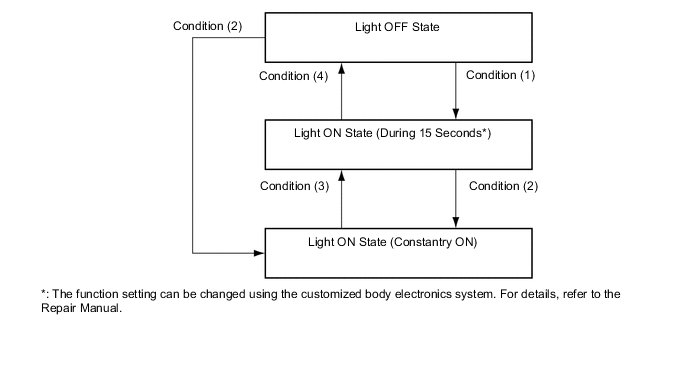
Condition Item Condition (1)
-
With engine switch OFF and all doors closed, key enters any actuation area around the doors. (Models with entry and start system)
-
Engine switch OFF and all doors closed, any door is unlocked.
-
Engine switch is turned from ACC, IG to OFF.
Condition (2)
-
Driver door or front passenger door is opened.
-
Rear passenger door is opened.
Condition (3)
-
Driver door or front passenger door is closed.
-
Rear passenger door is closed.
Condition (4)
-
More than approximately 15 seconds have elapsed since the light ON state (15 seconds duration)*.
-
All doors are closed, and are locked.
-
Engine switch is turned from OFF to ACC, IG.
-
Key is outside of all actuation area around the doors. (Models with entry and start system)
*: The function setting can be changed using the customized body electronics system. For details, refer to the Repair Manual.
-
-
-
Interior Footwell Light Control Function
-
The interior footwell light control consists primarily of the fade-in/fade-out function and timer illumination function.
-
The interior footwell light control operates as described in the diagram below when any one of the items for each condition is satisfied.
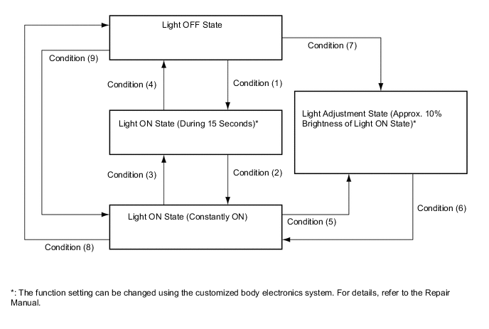
Condition Item Condition (1)
-
With engine switch OFF and all doors closed, any door is unlocked.
Condition (2)
-
Any door is open.
-
With shift lever at P position, engine switch is changed from OFF to IG.
Condition (3)
-
With engine switch ACC or OFF, all doors are closed.
-
With all doors closed, engine switch is changed from IG to OFF.
Condition (4)
-
More than 15 seconds have elapsed in the light ON state (15 seconds duration)*.
-
With engine switch OFF and all doors closed, all doors are locked.
Condition (5)
-
Shift lever is put into other than P position with engine switch IG.
Condition (6)
-
With engine switch IG, shift lever is put into P position or any door is opened with shift lever in any position except P.
Condition (7)
-
With shift lever in other than P position, engine switch is changed from OFF to IG.
Condition (8)
-
With engine switch OFF and all doors locked, all doors are closed.
Condition (9)
-
Any door is open.
-
With shift lever in P position, engine switch is changed from OFF to ON (IG).
*: The function setting can be changed using the customized body electronics system. For details, refer to the Repair Manual.
-
-
-
Side Step Light Control Function
-
The side step light control activates as described in the diagram below when one of items is in the respective state.
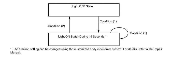
Condition Item Condition (1)
-
With engine switch OFF and all doors closed, key enters any actuation area around the doors.
-
With engine switch OFF, all doors closed and any door is unlocked.
-
With engine switch IG and shift lever in P position, all doors are unlocked by driver or front passenger door control switch.
-
A door other than the back door is open.
Condition (2)
-
More than 15 seconds have elapsed in the light ON state (15 seconds duration)*.
-
All doors are closed and locked.
-
Engine switch is ACC or IG.
-
Key is outside of all actuation area around the doors.
-
Shift lever is moved to a position other than P position with engine switch IG.
*: The function setting can be changed using the customized body electronics system. For details, refer to the Repair Manual.
-
-
-
Exterior Footwell Light Control
-
The exterior footwell light control consists primarily of the fade-in/fade-out function and timer illumination function.
-
The foot light control operates as described in the diagram below when any one of the items for each condition is satisfied.
Condition Item Condition (1)
-
With engine switch OFF and all doors closed, key enters any actuation area around the doors.
-
With engine switch OFF, all doors are closed and any door is unlocked.
-
With engine switch IG and shift lever in P position, all doors are unlocked by driver or front passenger door control switch.
Condition (2)
-
More than 15 seconds have elapsed in the light ON state (15 seconds duration)*.
-
All doors are closed and locked.
-
Engine switch is ACC or IG.
-
Key is outside of all actuation area around the doors.
-
Shift lever is moved to a position other than P position with engine switch IG.
*: The function setting can be changed using the customized body electronics system. For details, refer to the Repair Manual.
-
-
-
Battery Saving Control
-
Under the following condition, battery saving control turns off the lights illuminated by the illuminated entry control.
-
When any door is open, no door is opened or closed for approximately 20 minutes.
-
Engine switch is turned from ACC, IG to OFF.
-
-
Battery Saving Control
-
When the front room light, No. 1 room light and No. 2 room light are illuminated by the each switch, and vanity lights are illuminated, these lights are turn off after 20 minutes after the engine switch is turned OFF.
-
-
-