ENTRY AND START SYSTEM
-
System Diagram
-
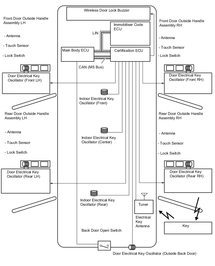
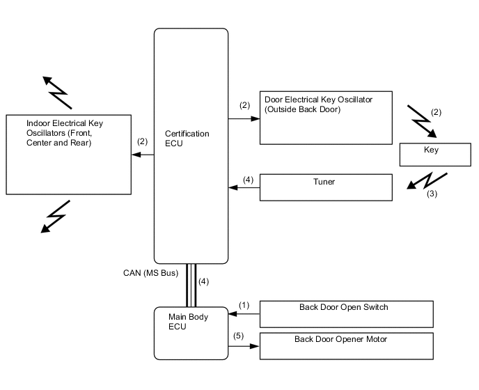
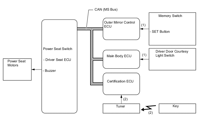
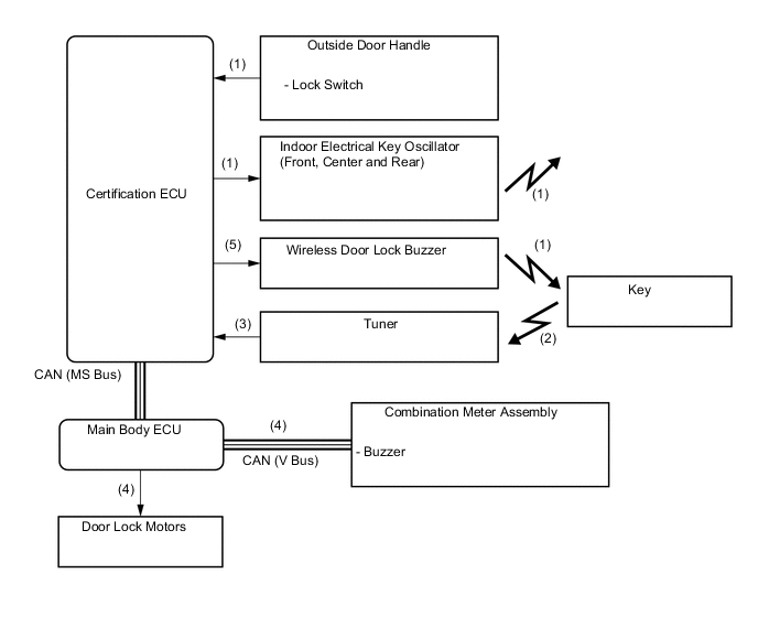
The certification ECU controls the entry function. The system diagram below shows the main components that relate to the function.
-
-
Layout of Main Components
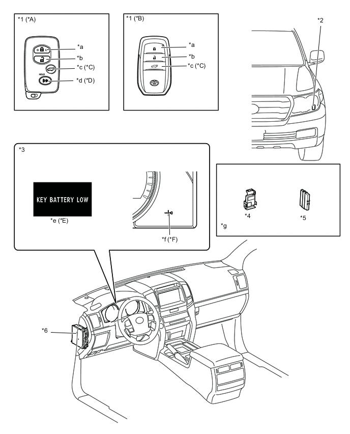
*A Except Models for China *B Models for China *C Models with Power Back Door System *D Models with the PANIC control *E Models with Optitron Type Combination Meter Assembly *F Models with Analog Type Combination Meter Assembly *1 Key *2 Wireless Door Lock Buzzer *3 Combination Meter Assembly *4 Certification ECU *5 Immobiliser Code ECU *6 Main Body ECU *a LOCK Button *b UNLOCK Button *c Power Back Door Button *d PANIC Button *e Multi-information Display *f Entry and Start System Warning Light *g Refer to the Service Bulletin for the installation of the part. - - 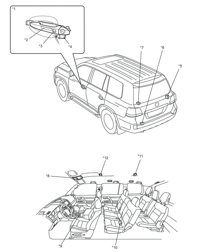
*1 Door Outside Handle Assembly *2 Touch Sensor
-
Antenna
*3 Door Electrical Key Oscillator *4 Lock Switch *5 Tuner *6 Door Electrical Key Oscillator (Outside Back Door) *7 Indoor Electrical Key Oscillator (Rear) *8 Roof Console Box Assembly
-
Front Interior Light
*9 Indoor Electrical Key Oscillator (Front) *10 Indoor Electrical Key Oscillator (Center) *11 No. 2 Room Light Assembly *12 No. 1 Room Light Assembly -
-
Function of Main Components
Component Function Key The key consists of a mechanical key, a transmitter for the wireless door lock remote control, a transceiver for the entry and start system, and a transponder chip for the engine immobiliser control. Certification ECU Controls the entry and start system in accordance with the signals from each oscillator, various switches, ECUs and the key.
-
Judges and certifies the ID code from the tuner.
-
Transmits the engine immobiliser deactivation signal to the immobiliser code ECU.
-
Transmits steering unlock signals to the steering lock ECU.
Main Body ECU Controls the entry and start system in accordance with the signals from the various switches, ECUs and the combination meter assembly.
-
Transmits the key certification request signals to the certification ECU in accordance with the engine switch signals, and turns the relays ON and OFF.
-
Receives the request signals from the certification ECU and actuates the door lock motor to unlock or lock the door.
Immobiliser Code ECU Receives and certifies the engine immobiliser deactivation signals transmitted from the certification ECU, and sends it to the ECM. Door Outside Handle Assembly Antenna Transmits the request signals. Touch Sensor Detects when a person touches the inside of an outer door handle. Lock Switch Transmits door lock request signals to the certification ECU. Door Oscillator (All Doors) Receives the request signals from the certification ECU, and creates an actuation area around the door. Indoor Electrical Key Oscillator (Front, Center and Rear) Receives the request signals from the certification ECU, and forms an actuation area around the back door. Door Electrical Key Oscillator (Outside Back Door) Receives the request signals from the certification ECU, and forms an actuation area around the back door. Tuner
-
Receives the ID code from the key in the actuation area and transmits it to certification ECU.
-
Receives the ID code from the key in the cabin and transmits it to certification ECU.
Back Door Open Switch Transmits a back door open request signal to the certification ECU via the main body ECU. Wireless Door Lock Buzzer Sounds as an answerback for entry lock or unlock to inform the driver. Combination Meter Assembly Multi-information Display*1 When the certification ECU detects human error, it warns the driver by sounding the wireless door lock buzzer and the buzzer in the combination meter assembly, and by illuminating a warning on the multi-information display*1, the master warning light and the entry and start system warning light*2, in accordance with the request signal from the certification ECU. Entry and Start System Warning Light*2 Master Warning Light Buzzer *1: Models with Optitron type combination meter assembly
*2: Models with analog type combination meter assembly
-
-
Construction and Operation
-
Key
-
The key consists of a mechanical key, a transmitter for the wireless door lock remote control and a transceiver for the entry and start system, and a transponder chip for the engine immobiliser control.
-
The transceiver function of the key receive signals from the oscillators and returns the ID code to the tuner.
-
The transmitter function for the wireless door lock remote control has a LOCK button, UNLOCK button, power back door button*1 and PANIC button*2.
-
The transponder chip in the key for the engine immobiliser control returns a signal to the engine switch as a response to the radio wave it received from the engine switch.
-
This mechanical key operates the driver door lock cylinder, and glove box lock cylinder, but cannot be used to start the engine. When the mechanical key is used, the cap on the driver door lock cylinder must be removed.
-
*1: Models with power back door system
-
*2: Models with the PANIC control
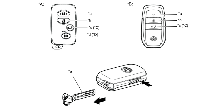
*A Except Models for China *B Models for China *C Models with Power Back Door System *D Models with the PANIC Control *a LOCK Button *b UNLOCK Button *c Power Back Door Button *d PANIC Button *e Mechanical Key - - -
-
-
Oscillator (Each Door, Font, Center and Rear, and Outside Back Door)
-
Each oscillator functions based on a request signal received from the certification ECU, and creates a key actuation area that is used to detect the presence of a key.
-
The actuation area formed by the door electrical key oscillator (front door and outside back door) is approximately 0.7 to 1.0 m (2.3 to 3.3 ft.) from the outside handle of the front doors, or the center of the rear bumper.
-
The actuation area of each door oscillator is formed by transmitting a request signal every 0.25 seconds while the engine switch is OFF and each door is locked. In this way it detects the proximity of a key. When locking the door using the lock switch on the outer door handle, the actuation area is formed when the lock switch is pressed.
-
The actuation area of the door electrical key oscillator (outside back door) is formed when the back door open switch is ON. It is formed twice to allow the key to be verified.
-
The actuation area of the indoor electrical key oscillator (front, center and rear) is formed when the driver door is opened or closed, when the start button is pressed, when a warning is activated, or when the lock switch is ON.
-
-
-
-
Entry Function Operation
-
General
-
The entry function has the following functions.
Function Outline Mechanical Key The operation is the same as a usual mechanical key. Wireless Door Lock Remote Control This function is a convenient system for locking and unlocking the doors at a distance. The operation is same as a standard wireless door lock remote control system. Entry Illumination When a key enters the actuation area of any door oscillator, the front interior light, rear interior light, and engine switch illumination illuminate. Entry Unlock When a key is located in the actuation area any door oscillator, the door will unlock after the inside of an outside door handle is touched. Entry Unlock Mode Switching Allows selection of one of two modes that can be activated with the entry unlock function.
-
Driver Door Mode
-
All Door Mode
Entry Lock When a key is located in the actuation area of any door oscillator and the engine switch is OFF, the door can be locked by merely pressing the lock switch on the outside door handle. Back Door Open When a key is in the actuation area of the door electrical key oscillator (outside back door), the back door can be opened by merely pressing the back door open switch. Window and Sliding Roof Close With the key in the actuation area of any door oscillators, all open windows and the sliding roof are closed when the lock switch on the door outside handle is pressed for 3 seconds or more. Memory Call This function operates the driving position memory system in accordance with the key ID. Prevention of Key Confinement Prevents the key from being confined in the vehicle when a door is locked with the outside door handle while the key is still inside the vehicle. Warning When any of the situations below occur, the entry and start system causes the certification ECU to sound the buzzer in the combination meter and the wireless door lock buzzer, and indicate a warning on the multi-information display in order to the alert driver.
-
An exit warning if the shift lever is in a position other than P and the engine switch is in a mode other than OFF.
-
An exit warning if the shift lever is in P and the engine switch is in a mode other than OFF.
-
A warning if the occupant leaves with the key in inappropriate circumstances.
-
A warning if the engine switch is operated while the key is outside the actuation area.
-
A warning if the entry lock button on the door handle is operated while the key is inside the vehicle.
-
A warning if the key battery is weak.
-
A warning if any door is ajar.
Battery Saving If the key remains within the actuation area of any door oscillator, the system maintains periodic communication with key. Therefore, if the vehicle remains parked in that state for a long time, the key battery and the vehicle battery could be drained. Key Cancel The following key functions can be cancelled by following certain procedures.
-
Entry Unlock/Lock
-
Back Door Open
-
Memory Call
-
Prevention of Key Confinement
-
Warning
Key Code Registration A total of 7 keys can be registered. Enables the registering (writing and storing) of transmitter recognition codes in the EEPROM that is contained in the certification ECU. -
-
-
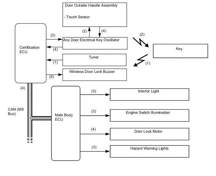
Entry Unlock Function
-
When a key enters the actuation area of any door oscillator, the certification ECU judges and certifies the key ID code received from the tuner.
-
After the key certification OK is confirmed, the certification ECU transmits an unlock stand-by signal to the touch sensor of the relevant door.
-
If the touch sensor is touched during this condition, the certification ECU transmits a door unlock signal to the main body ECU and unlocks the door.
-
At the same time, the main body ECU transmits the lighting signals to the engine switch illumination and interior lights (front and rear), and turns ON these illuminations (Illuminated Entry Function).
-
The certification ECU sounds the wireless door lock buzzer twice and main body ECU flashes the hazard warning lights twice as an answerback for entry unlock.
-
-
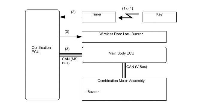
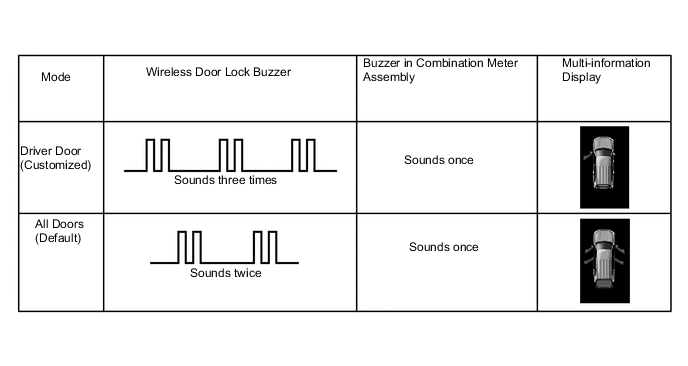
Entry Unlock Mode Switching
-
When the engine switch is OFF, press the lock button and one of the other buttons on the key at the same time for approximately 5 seconds while the key is in the actuation area.
-
The certification ECU receives this signal from the tuner and switches the entry unlock mode.
-
The certification ECU sounds the wireless door lock buzzer and the buzzer of the combination meter assembly to inform the user that the mode has been switched.
-
If the entry unlock mode needs to be switched again, press the lock button and one of the other buttons on the key at the same time for approximately 5 seconds after the LED of the key goes off, thereby the mode changes in the following sequence: Driver Door and All Doors.
Tech Tips
This function only switches the entry unlock mode of the entry and start system. It is not applied to the unlock function using the wireless door lock remote control.
-
-
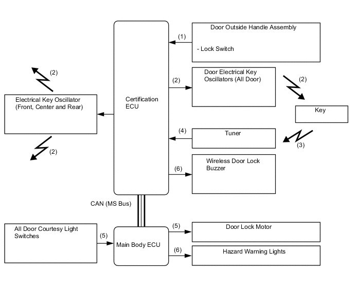
Entry Lock Function
-
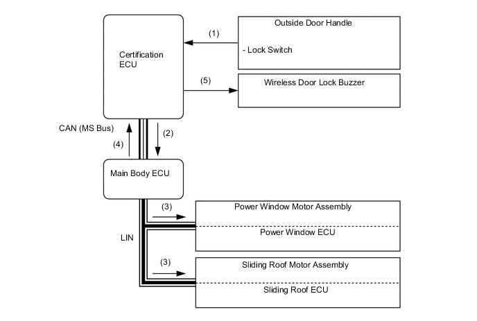
This signal is transmitted to the certification ECU when the driver (who has the key in their possession), exits the vehicle and presses the lock switch on the outside door handle.
-
The certification ECU transmits a request signal for all door and indoor oscillators to form actuation areas.
-
The key receives this signal and returns the ID code to the tuner
-
The certification ECU judges and certifies the ID code from the tuner. It then checks the location of the key, and if all the doors are closed, the ECU transmits a door lock signal to the main body ECU.
-
When the main body ECU receives the signal and judges that all the doors are closed, it actuates the door lock motors to lock the doors.
-
The main body ECU blinks hazard warning lights once and the certification ECU sounds the wireless door lock buzzer once as an answerback for the entry lock function.
-
-
Entry Back Door Open
-
The unlock signal is transmitted to the certification ECU when the driver pushes the back door open switch with the key carried in the driver's possessions.
-
The certification ECU transmits a request signal for electrical key oscillators (front, center, rear and outside back door) to form actuation areas.
-
The key transmits the ID code to the tuner.
-
The certification ECU judges and certifies the ID code, and checks the location of the key. The ECU transmits a back door open signal to the main body ECU.
-
The main body ECU receives this signal and actuates the back door opener motor to open the back door.
-
-
Window and Sliding Roof Close Function
-
After all the doors have been locked, and the driver keeps pressing the lock switch on the outside door handle for approximately 3 seconds, the certification ECU receives continuous door lock switch ON signals.
-
The certification ECU transmits these signals to the main body ECU.
-
The main body ECU transmits the window and sliding roof close request signals to the power window master switch and sliding roof ECU built into the sliding roof motor assembly. The power window master switch transmits the window close request signals to the power window ECU built into the power window motor assembly. These ECUs operate their motors to close windows and sliding roof.
-
The certification ECU sounds the wireless door lock buzzer as an answer back for the window and sliding roof close function.
-
-
Memory Call Function
-
General
-
The memory call function while using a key utilizes the key ID to restore the driver seat position (driving position memory system), steering column position and outer rear view mirror position, automatically, which increases driver convenience.
Condition Outline Memory Registration When all the following conditions are met, the key ID is recorded.
-
Engine switch is OFF.
-
Driver door is closed.
-
Memory No. (1, 2 or 3) button is pressed and held.
-
LOCK or UNLOCK button in the key pressed and held.
Memory Call Operation After the door is unlocked using the entry and start system function or the wireless door lock remote control function, if the driver door is opened, the memory call function is operated. Memory Call Cancel When all the following conditions are met, the memory call function can be disabled.
-
Engine switch is OFF.
-
Driver door is closed.
-
SET button is pressed and held.
-
LOCK or UNLOCK button in the key pressed and held.
-
-
Memory Registration
-
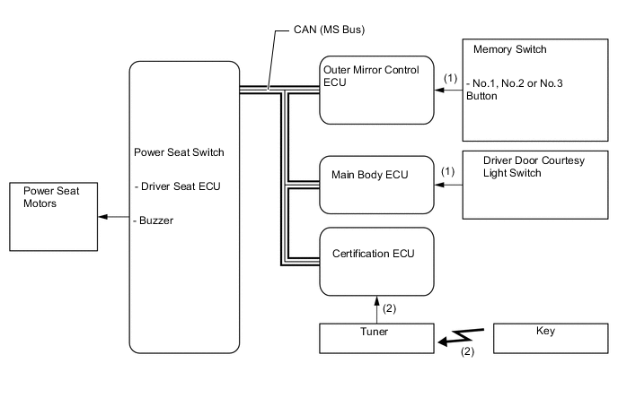
The driver seat ECU enters the key ID registration mode (linking mode), if the seat memory No. 1, No. 2 or No. 3 button is pressed with the engine switch OFF and driver door closed.
-
In this condition, when the LOCK or UNLOCK button on the key is pressed, the key ID is transmitted from certification ECU to the driver seat E
-
The driver seat ECU records the key ID and each position into the memory.
-
When the driver seat ECU completes recording, it beeps the buzzer in the driver seat ECU once as an answer back.
-
-
Memory Call Operation
-
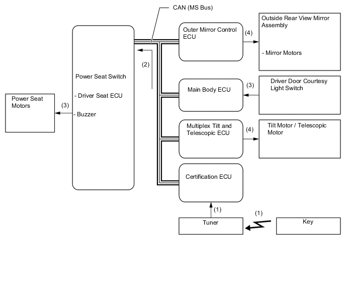
When the UNLOCK button on the key is pressed or the key enters the actuation area, the key ID is input to certification ECU through the tuner.
-
The certification ECU transmits the key ID to the driver seat ECU.
-
If the driver door is opened, the driver seat ECU outputs a key ID memory restoration signal from certification ECU to each ECU and activates the drive seat motors.
-
When each ECU receives this signal, it activates each actuator.
-
-
Memory Call Cancel
-
If the SET button is pressed when the engine switch is OFF and the driver door is closed, the driver seat ECU enters the memory call cancel mode.
-
In this condition, when LOCK or UNLOCK button in a key is pressed, the key ID is transmitted from certification ECU to the driver seat ECU.
-
If the key ID has already been registered, the driver seat ECU will cancel the key ID memory call function. To perform the key ID memory call function again, it is necessary to register the key ID.
-
When the driver seat ECU completes switching, it beeps the buzzer in the driver seat ECU twice as an answer back.
-
-
-
Prevention of Key Confinement
-
When the door is locked with the outside door handle while the key is still inside the vehicle, the certification ECU receives this signal and transmits a request signal for the indoor electrical key oscillators (front, center and rear) to form a actuation area.
-
The key receives this signal and returns the ID code to the tuner.
-
The certification ECU judges and certifies the ID code, and checks the location of the key. The ECU transmits a door unlock signal to the main body ECU.
-
The main body ECU receives the signal and operates each door lock motor to unlock the doors.
-
The certification ECU sounds the wireless door lock buzzer and the buzzer of the combination meter assembly as an answerback for the unlock function that was performed.
-
-
Warning
-
General
-
When any of the situations below occur, the entry and start system causes the certification ECU to sound a buzzer in the combination meter assembly and the wireless door lock buzzer, and illuminate the multi-information display or the entry and start system warning light in order to the alert the driver.
Situation Condition A* The shift lever is in a position other than P when the driver gets out of the vehicle. B The key is left in the vehicle. C The shift lever is in the P position when the driver gets out of the vehicle. D A door is ajar. E Any passenger carries the key out of the vehicle. F The key is not within the actuation areas. G The key is left in the cabin. H The key battery is low. I Steering lock does not release. J The steering lock mechanism is malfunctioning. K The main body ECU is malfunctioning. L The engine start method is displayed. *: Only for models with automatic transmission
-
-
Situation: A
There are two patterns for situation A.
-
Pattern 1: When the shift lever is in a position other than P, the driver opens the door and attempts to get out of the vehicle.
-
Pattern 2: Under the conditions of pattern 1, the driver closes the door and attempts to leave the vehicle holding the key.
In these situations, the following control is performed:
Pattern 1 Possible Effects without Warning Sudden vehicle start, Vehicle theft, Vehicle roll-away Warning Condition The warning is activated when all of the following conditions are met:
-
Engines switch is in a mode other than OFF.
-
Shift lever is in any position except P.
-
Vehicle speed is 0 km/h (0 mph).
-
Driver door is opened.
Combination Meter Assembly Buzzer Continuous sound Multi-information Display The following warnings are alternately displayed:
-
SHIFT TO [P] RANGE
Master Warning Light - Entry and Start System Warning Light* - Wireless Door Lock Buzzer - Engine Switch Indicator Light - Warning Stop Condition The warning is stopped when one of the following conditions is met:
-
Engine switch is OFF.
-
Shift lever is in the P position.
-
Vehicle speed is above 0 km/h (0 mph).
-
Driver door is closed.
*: Models with analog type combination meter assembly
Pattern 2 Possible Effects without Warning Sudden vehicle start, Vehicle theft, Vehicle roll-away Warning Condition The warning is activated when all of the following conditions are met:
-
Shift lever is in any position except P.
-
Engines switch is in a mode other than OFF.
-
Vehicle speed is 0 km/h (0 mph).
-
Key is not in the vehicle.
-
Driver door is opened → closed.
Combination Meter Assembly Buzzer Sounds continuously Multi-information Display The following warnings are alternately displayed:
-
SHIFT TO [P] RANGE
-
KEY NOT DETECTED
Master Warning Light Flash Entry and Start System Warning Light* Illuminate Wireless Door Lock Buzzer Sounds continuously Engine Switch Indicator Light - Warning Stop Condition Key is in the vehicle.
-
The wireless door lock buzzer stops.
-
Multi-information Display:
-
SHIFT TO [P] RANGE
Vehicle speed is above 0 km/h (0 mph).
-
The wireless door lock buzzer stops.
-
Multi-information Display:
-
KEY NOT DETECTED
Engine switch is OFF.
-
All warning operations stop.
*: Models with analog type combination meter assembly
-
-
Situation: B
There are two patterns for situation B.
-
Pattern 1: While the driver's door is open, the driver changes the power source mode to ACC and attempts to leave the vehicle.
-
Pattern 2: While the driver's door is open, the driver changes the power source mode from ON to OFF and attempts to leave the vehicle.
In these situations, the following control is performed:
Pattern 1 and Pattern 2 Possible Effects without Warning Vehicle theft Warning Condition The warning is activated when one of the following conditions is met:
-
Engine switch is in ACC mode and the driver door is opened.
-
Engines switch is in OFF mode the steering is unlocked, and the driver door is opened.
Combination Meter Assembly Buzzer Continues to sound at short and even intervals Multi-information Display - Master Warning Light - Entry and Start System Warning Light* - Wireless Door Lock Buzzer - Engine Switch Indicator Light - Warning Stop Condition The warning is stopped when one of the following conditions is met:
-
Engine switch is in IG-ON mode.
-
Driver door is closed.
-
Engine switch is in OFF mode and the steering is locked.
*: Models with analog type combination meter assembly
-
-
Situation: C
There are two patterns for situation C.
-
Pattern 1: When the engine is left running and the shift lever is in the P position, the driver closes the driver's door and attempts to leave the vehicle while holding the key.
-
Pattern 2: Under the conditions of pattern 1, the driver presses the lock switch on the door outside handle.
In these situations, the following control is performed:
Pattern 1 Possible Effects without Warning Vehicle theft, The engine cannot be restarted, Discharged battery Warning Condition The warning is activated when all of the following conditions are met:
-
Engines switch is in a mode other than OFF.
-
Shift lever is P.*1
-
Key is not in the vehicle.
-
Driver door is opened → closed.
Combination Meter Assembly Buzzer Sounds once Multi-information Display The following warnings are alternately displayed:
-
KEY NOT DETECTED
Master Warning Light Flash Entry and Start System Warning Light*2 Illuminate Wireless Door Lock Buzzer Sounds three times Engine Switch Indicator Light - Warning Stop Condition The warning is stopped when one of the following conditions is met:
-
Engine switch is OFF.
-
Key is in the vehicle.
*1: Models with automatic transmission
*2: Models with analog type combination meter assembly
Pattern 2 Possible Effects without Warning Vehicle theft, Discharged battery Warning Condition The warning is activated when all of the following conditions are met:
-
Shift lever is P.*1
-
Vehicle speed is 0 km/h.
-
Engines switch is in a mode other than OFF.
-
All doors are closed.
-
The key is outside the vehicle (within one of the actuation areas).
-
Lock switch on the door outside handle is ON
Combination Meter Assembly Buzzer - Multi-information Display - Master Warning Light - Entry and Start System Warning Light*2 - Wireless Door Lock Buzzer Sounds for 60 seconds Engine Switch Indicator Light - Warning Stop Condition The warning is stopped when one of the following conditions is met:
-
The engine switch is OFF and the key is not within the actuation areas.
-
Key is in the vehicle.
-
Vehicle speed is above 0 km/h.
*1: Models with automatic transmission
*2: Models with analog type combination meter assembly
-
-
Situation: D
The lock switch on the door outside handle is pressed to perform entry lock with a door open.
In this situation, the following control is performed:
Possible Effects without Warning Vehicle theft Warning Condition The warning is activated when all of the following conditions are met:
-
Engines switch is OFF.
-
Any doors are opened.
-
Entry lock button on the outer door handle is operated.
Combination Meter Assembly Buzzer - Multi-information Display - Master Warning Light - Entry and Start System Warning Light* - Wireless Door Lock Buzzer Sounds for 10 seconds Engine Switch Indicator Light - Warning Stop Condition The warning is stopped when one of the following conditions is met:
-
Engine switch is in a mode other than OFF.
-
All doors are closed.
-
Wireless door lock remote function is unlocked.
-
Entry unlock is operated.
-
10 seconds have elapsed since the wireless door lock buzzer was activated.
*: Models with analog type combination meter assembly
-
-
Situation: E
When the engine is left running, a passenger leaves the vehicle holding the key.
In this situation, the following control is performed:
Possible Effects without Warning The engine cannot be restarted Warning Condition The warning is activated when all of the following conditions are met:
-
Engine switch is in a mode other than OFF.
-
Door except driver door is opened → closed.
-
Vehicle speed is 0 km/h (0 mph).
-
Key is not in the vehicle.
Combination Meter Assembly Buzzer Sounds once Multi-information Display The following warnings are alternately displayed:
-
KEY NOT DETECTED
Master Warning Light Flash Entry and Start System Warning Light* Illuminate Wireless Door Lock Buzzer Sounds 3 times Engine Switch Indicator Light - Warning Stop Condition The warning is stopped when one of the following conditions is met:
-
Engine switch is OFF.
-
Vehicle speed is above 0 km/h (0 mph).
-
Key is in the vehicle.
*: Models with analog type combination meter assembly
-
-
Situation: F
When the key is not in the cabin or the key does not operate properly, the driver attempts to start the engine or change the engine switch to ON.
In this situation, the following control is performed:
Possible Effects without Warning Confuses the user Warning Condition The warning is activated when all of the following conditions are met:
-
Engine switch is pushed.
-
Key is not in the vehicle.
Combination Meter Assembly Buzzer Sounds once Multi-information Display The following warnings are alternately displayed:
-
KEY NOT DETECTED
Displayed for 10 seconds(and then automatically turned off)
Master Warning Light Flash Entry and Start System Warning Light* Illuminate Wireless Door Lock Buzzer - Engine Switch Indicator Light - Warning Stop Condition Check if the key is in the detection area.
If the key is in the detection area, press the wireless door lock switch and confirm that the indicator comes on. If the indicator does not come on, replace the key battery with a new one.
*: Models with analog type combination meter assembly
-
-
Situation: G
The lock switch on the door outside handle is pressed to perform entry lock with the key left in the cabin.
In this situation, the following control is performed:
Possible Effects without Warning Vehicle theft Warning Condition The warning is activated when all of the following conditions are met:
-
Engine switch is OFF.
-
All doors are closed.
-
Key is not in the vehicle.
-
Lock switch on the door outside handle switch is ON.
Combination Meter Assembly Buzzer - Multi-information Display - Master Warning Light - Entry and Start System Warning Light* - Wireless Door Lock Buzzer Sounds for 2 seconds Engine Switch Indicator Light - Warning Stop Condition The key is removed from the cabin and the lock switch on the door outside handle is pressed again. *: Models with analog type combination meter assembly
-
-
Situation: H
The vehicle is driven using a key that has a low battery.
In this situation, the following control is performed:
Possible Effects without Warning Entry and start system does not function Warning Condition The warning is activated when all of the following conditions are met:
-
Engine switch to OFF after being left in IG-ON for over 20 minutes.
-
Key battery voltage is low.
-
Key is in the vehicle.
Combination Meter Assembly Buzzer Sounds once Multi-information Display The following warnings are alternately displayed:
-
KEY BATTERY LOW
Displayed for 10 seconds(and then automatically turned off)
Master Warning Light Illuminate Entry and Start System Warning Light* - Wireless Door Lock Buzzer - Engine Switch Indicator Light - Warning Stop Condition Check if the key is in the detection area.
If the key is in the detection area, press the wireless door lock switch and confirm that the indicator comes on. If the indicator does not come on, replace the key battery with a new one.
*: Models with analog type combination meter assembly
-
-
Situation: I
Steering lock cannot be released.
In this situation, the following control is performed:
Possible Effects without Warning Steering usability function Warning Condition The Steering lock cannot be released, thus the engine is prevented from starting. Combination Meter Assembly Buzzer - Multi-information Display The following warnings are alternately displayed:
-
STEERING LOCK ACTIVE
Displayed for 15 seconds(and then automatically turned off)
Master Warning Light Illuminate Entry and Start System Warning Light* - Wireless Door Lock Buzzer - Engine Switch Indicator Light The green indicator blinks at 1 second intervals (goes off automatically in 30 seconds). Warning Stop Condition The power switch is pressed while the steering wheel is turned left and right, and the steering lock successfully disengages. *: Models with analog type combination meter assembly
-
-
Situation: J
A malfunction of the steering lock ECU is detected.
In this situation, the following control is performed:
Possible Effects without Warning Malfunction detection Warning Condition A malfunction of the steering lock ECU is detected. Combination Meter Assembly Buzzer Sounds once Multi-information Display The following warnings are alternately displayed:
-
CHECK STEERING LOCK SYSTEM
Master Warning Light Illuminate Entry and Start System Warning Light* - Wireless Door Lock Buzzer - Engine Switch Indicator Light The amber indicator blinks at 2 second intervals.( goes off automatically in 15 seconds) Warning Stop Condition The steering lock ECU returns to normal. *: Models with analog type combination meter assembly
-
-
Situation: K
A malfunction of the main body ECU is detected.
In this situation, the following control is performed:
Possible Effects without Warning Malfunction detection Warning Condition A malfunction in the main body ECU is detected. Combination Meter Assembly Buzzer - Multi-information Display - Master Warning Light - Entry and Start System Warning Light* - Wireless Door Lock Buzzer - Engine Switch Indicator Light The amber indicator blinks at 2 second intervals. Warning Stop Condition The main body ECU returns to normal. *: Models with analog type combination meter assembly
-
Situation: L
A warning message appears on the meter when the driver does not follow the proper procedure to start the vehicle.
In this situation, the following control is performed:
Possible Effects without Warning Usability function Warning Condition The warning is activated when all of the following conditions are met:
-
Engine switch is in a mode other than ON.
-
Any doors are closed → opened.
-
The engine switch is changed from OFF to ACC more than once with the power off and brake pedal not depressed.
Combination Meter Assembly Buzzer Sounds once Multi-information Display The following warnings are alternately displayed:
-
DEPRESS BRAKE PEDAL AND PUSH ENGINE SWITCH TO START
Master Warning Light - Entry and Start System Warning Light* - Wireless Door Lock Buzzer - Engine Switch Indicator Light - Warning Stop Condition The warning is stopped when one of the following conditions is met:
-
10 seconds have elapsed since a warning message was displayed.
-
The engine switch is pushed with the brake pedal depressed or the engine switch is OFF.
*: Models with analog type combination meter assembly
-
-
-
Battery Saving
-
Vehicle Battery Saving Function
In the entry and start system, signals are emitted outside the vehicle at a prescribed interval (250 msec.) when the doors are locked. Therefore, the vehicle battery could be drained if the vehicle remains parked for a long time. For this reason, the controls listed below are effected.
Condition Control No response from key for 10 to 14 days Signal transmission interval is extended from 250 msec. to 750 msec. No response from key for 15 to 30 days Signal transmission interval is extended from 750 msec. to 2250 msec. No response from key for more than 31 days Automatically deactivates entry and start system. Reinstatement Conditions A wireless door lock remote control signal (lock and unlock) is input and the ID matches. A user is carrying the key and pushes a lock switch on an door outside handle. A door is locked or unlocked using the mechanical key. -
Key Battery and Vehicle Battery Saving Function
In the entry and start system, if the key is constantly located within the vehicle exterior actuation area of the doors, the system will maintain periodic communication with the key. Therefore, if the vehicle remains parked in that state for a long time, the key battery and the vehicle battery could be drained.For this reason, if this state continues longer than 10 minutes, the entry and start system automatically deactivates.
Reinstatement Conditions A wireless door lock remote control signal (lock and unlock) is input and the ID matches. user who has the key in their possession pushes a lock switch on an door outside handle. A door is locked or unlocked using the mechanical key.
-
-
Key Cancel
-
Key cancel is operated when certain operations are performed with the vehicle in the following condition:
-
Engine switch is OFF.
-
Driver door is closed.
-
Driver door is unlocked.
-
-
The operation procedure is as follows:
-
Unlock once with the UNLOCK button on the key.
-
Open the driver door within 5 seconds.
-
Unlock twice with the UNLOCK button on the key within 5 seconds.
-
Repeat open → close twice for the driver door within 30 seconds, and open again. (Driver Door: Open → Close → Open → Close → Open)
-
Unlock twice with the UNLOCK button on the key within 30 seconds.
-
Repeat open → close once for the driver door within 30 seconds, and open again. (Driver Door: Open → Close → Open)
-
Close the driver door within 5 seconds.
When key cancel is activated, the wireless door lock buzzer sounds twice.
To return to the original condition, perform the procedures again. When it is returned to its original condition, the wireless door lock buzzer sounds once.
-
-
-
Key Code Registration Function
-
The table below shows the four special coded ID registration function modes through which up to seven different codes can be registered. The codes are electronically registered (written to and stored) in the EEPROM.
Mode Function Rewrite Erases all previously registered codes and registers only the newly received codes. This mode is used whenever a transmitter or the integration relay is replaced. Add Adds a newly received code while preserving previously registered codes. This mode is used when adding a new transmitter. If the number of codes exceeds 4, the oldest registered code is erased first. Confirm Confirms how many codes are currently registered. When adding a new code, this mode is used to check how many codes already exist. Prohibit To delete all the registered codes and to prohibit the wireless door lock function.This mode is used when a transmitter (key) is lost.
-
-