ENTRY AND START SYSTEM
-
General
-
This use the entry and start system, which starts the engine when the push-type engine switch is pressed while the brake pedal is depressed and a key is carried by the driver.
-
This function has different power source control patterns to suit the state of the brake pedal and shift lever position.
-
Along with the adoption of the start function, an engine cranking hold function is used.

-
-
System Diagram
-
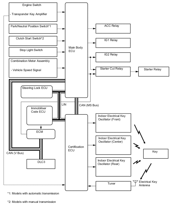
The main body ECU controls the push button start function. The system diagram below shows the components that relate to this function.
-
-
Layout of Main Components
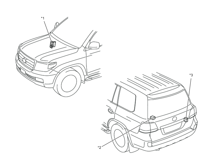
*1 ECM *2 Indoor Electrical Key Oscillator (Rear) *3 Tuner - - 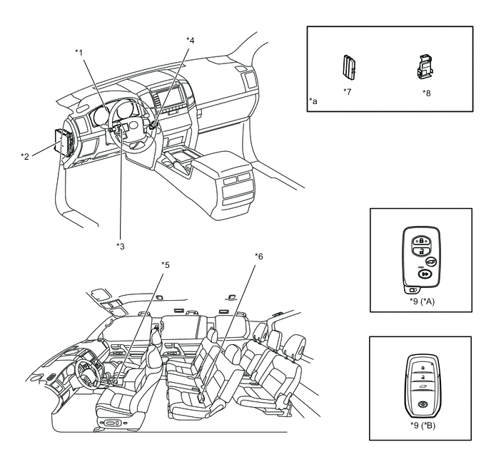
*A Except Models for China *B Models for China *1 Combination Meter Assembly *2 Main Body ECU *3 Steering Lock Actuator Assembly
-
Steering Lock/Unlock Detection Switch
-
Steering Lock ECU
-
Steering Lock Motor
*4 Engine Switch
-
Transponder Key Amplifier
*5 Indoor Electrical Key Oscillator (Front) *6 Indoor Electrical Key Oscillator (Center) *7 Immobiliser Code ECU *8 Certification ECU *9 Key - - *a Refer to the Service Bulletin for the installation of the part. - - -
-
Function of Main Components
Component Function Engine Switch
-
Transponder Key Amplifier
-
Transmits the engine switch signal to the main body ECU.
-
Informs the driver of any power source or system abnormality through the illumination stage of the indicator light.
-
Receives the ID code and transmits it to the certification ECU when the key battery is too weak to respond to the tuner based on the room oscillators.
Key Receives the signals from the oscillators and returns the ID code to the tuner. Indoor Electrical Key Oscillators
-
Front, Center and Rear
Receives a request signal from the certification ECU and forms the actuation area in the vehicle interior. Tuner Receives the ID code from the key and transmits it to certification ECU. Main Body ECU
-
Switches the power source among four modes (OFF, ACC, IG-ON, START) in accordance with the shift position and the state of the stop light switch*1 or clutch start switch*2.
-
Controls the entry and start system in accordance with the signals received from the switches and each ECU.
Certification ECU Certifies the ID code received from the tuner and transmits the certification results to the immobiliser code ECU and steering lock ECU. Stop Light Switch*1 Outputs the state of the brake pedal to main body ECU. Clutch Start Switch*2 Outputs the state of the clutch pedal to the main body ECU. Immobiliser Code ECU Receives the steering unlock or engine immobilizer disengage signals from the certification ECU, certifies them, and transmits each disengage signal to the steering lock ECU or ECM. Steering Lock ECU Receives the steering lock/unlock signal from immobilizer code ECU, and activates the steering lock motor. ECM
-
Receives the engine start request signal from the main body ECU, and starts the engine.
-
Receives the engine immobiliser disengage/engage signal from the immobiliser code ECU, and disengages or engages the engine immobiliser.
Shift Position Sensor*1 Detects the shift position and transmits a shift position signal to the ECM. Combination Meter Assembly Transmits the vehicle speed signal to the main body ECU. *1: Models with automatic transmission
*2: Models with manual transmission
-
-
Construction and Operation
-
Engine Switch
-
The engine switch consists of a momentary type switch, two color (Amber, Green) LEDs, and transponder key amplifier.
-
The amber and green LEDs are for the indicator light.
-
The driver can determine the present power source and check whether the engine can start or not in accordance with the illumination state of the indicator light.
-
When the main body ECU detects an abnormality with the entry and start system, it makes the amber indicator light flash. If the engine is stopped in this state, it might not be possible to restart it.

*1 Indicator Light - - 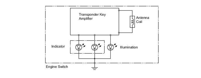
Indicator Light Condition Power Source Condition Indicator Light Condition Brake pedal not depressed*1 or clutch pedal not depressed*2 Brake pedal depressed with shift lever in P or N*1 or Clutch pedal depressed*2 OFF OFF ON (Green) ACC, IG-ON ON (Amber) ON (Green) START OFF OFF Steering lock not unlocked Flashes (Green) for 30 seconds Flashes (Green) for 30 seconds Entry and Start System Malfunction Flashes (Amber) for 15 seconds Flashes (Amber) for 15 seconds *1: Models with automatic transmission
*2: Models with manual transmission
-
-
-
Main Body ECU
-
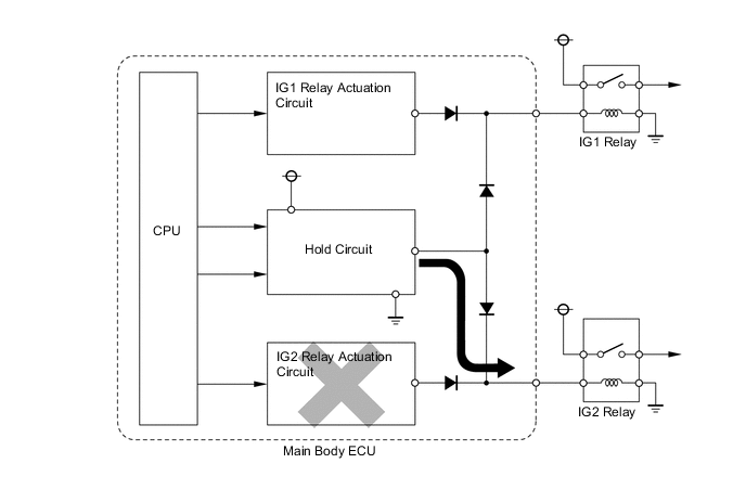
The main body ECU consists of the IG relay No. 1 and No. 2 actuation circuits, CPU, and hold circuit.
-
The hold circuit is installed to prevent the power supply to the relays from being cut off when an abnormality occurs in IG relay No. 1 or No. 2 actuation circuits while driving.
Tech Tips
The main body ECU constantly stores the present power source state in its memory. Therefore, if the power to main body ECU is interrupted due to the removal of the battery, the main body ECU restores the power source after the battery is reconnected.
For this reason, if the battery is removed when the power switch is in a state other than OFF, the power will be restored to the vehicle at the same time the power is restored to main body ECU (by reconnecting the battery).
Therefore, before removing the battery, be sure to turn the power switch OFF.
-
-
Steering Lock System
-
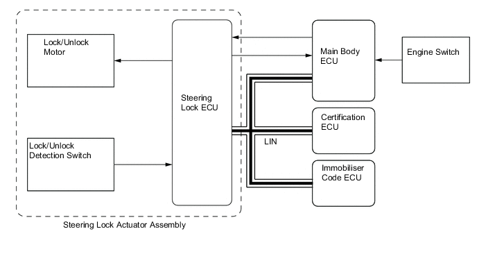
According with the use of the entry and start system, a steering lock system which uses a lock/unlock motor to lock and unlock the steering wheel is used. This system consists primarily of the steering lock actuator assembly, main body ECU, certification ECU and immobiliser code ECU.
-
The steering lock ECU is integrated in the steering lock actuator assembly, and it controls the lock bar operation in the steering lock assembly through the lock/unlock motor.
-
The steering lock ECU detects the position (lock/unlock) of the lock bar and transmits this information to the main body ECU and certification ECU.
-
In this system, the certification ECU determines whether to lock or unlock the steering based on communication with the main body ECU. Then, the certification ECU sends lock or unlock command signals to the steering lock ECU through the immobiliser code ECU. Upon receiving the signals, the steering lock ECU operates the lock/unlock motor to lock or unlock the steering wheel.
Tech Tips
It is not possible to replace only the steering lock ECU in the steering lock actuator assembly. Therefore, if a malfunction occurs in the ECU, the entire steering lock actuator assembly must be replaced.
-
-
-
Start Function Operation
-
General
-
The start function has different power source patterns to suit the brake pedal state and shift lever position.
Pattern Brake*1 or Clutch*2 Pedal Shift Lever*1 Power Source Pattern A Depressed P or N When the engine switch is pushed once:
-
OFF → IG-ON (after engine is started)
B Not Depressed P The power source mode changes repeatedly in the following sequence when the engine switch is pushed:
-
OFF → ACC → IG-ON → OFF
C Other Than P Position The power source mode changes repeatedly in the following sequence when the engine switch is pushed:
-
OFF → ACC → IG-ON → ACC
D - P When the engine switch is pushed in the IG-ON condition:
-
IG-ON (engine is started or not started) → OFF
E - Other Than P Position When the engine switch is pushed in the IG-ON condition:
-
IG-ON (engine is started or not started) → ACC
*1: Models with automatic transmission
*2: Models with manual transmission
Figure 1. Transition of Power Source (Models with Automatic Transmission)
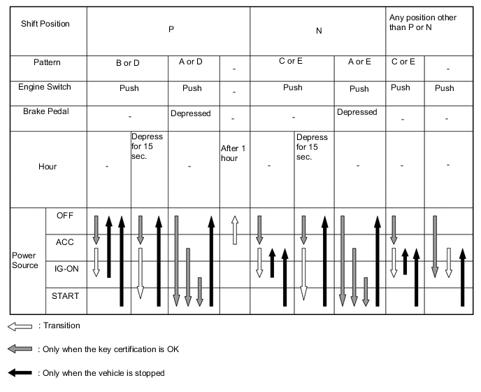
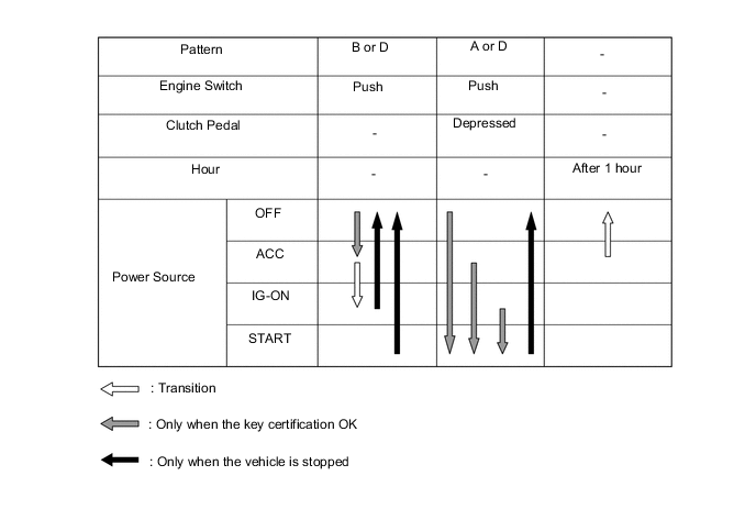
Figure 2. Transition of Power Source (Models with Manual Transmission)
Tech Tips
-
Normally, the operation of the engine switch is disabled while the vehicle is being driven. However, in an emergency, the driver can stop the engine while the vehicle is in motion by pressing the engine switch for approximately 3 seconds or more to turn the power source from IG-ON to ACC.
-
If no signals are transmitted to the main body ECU due to malfunctions in the stop light switch, the engine may not start when the engine switch is pressed with the brake pedal depressed. In such cases, performing the following procedure may enable the engine to start: 1) press the engine switch to turn the power source from OFF to ACC, and 2) press the engine switch again and hold it for 15 seconds or more.
-
The above two operations must be applied only in emergency situations. Under normal conditions, the engine must not be stopped by pressing the engine switch during driving or started without depressing the brake pedal when the shift lever is in any position other than P or N.
-
-
-
Pattern A: OFF → IG-ON (after the engine is started)
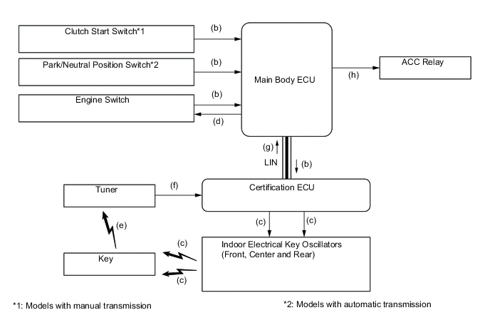
Step System Operation (a) The driver holds the key and enters the vehicle. (b) When the driver presses the engine switch once with the following conditions satisfied, the main body ECU recognizes the engine switch signal and transmits the key certification request to the certification ECU.
-
Clutch pedal depressed. *1
-
Shift position is P or N. *2
-
Brake pedal depressed. *2
-
Engine switch is OFF.
(c) The certification ECU receives the certification request signal and transmits a request signal to the indoor electrical key oscillators. These oscillators then transmit the request signal. (d) The brake pedal*2 or the clutch pedal*1 is depressed, so the main body ECU turns ON the green indicator light in the engine switch. (e) The moment the key receives the request signal, it transmits its ID code to the tuner. The signal includes the response code. (f) The tuner receives this code and transmits it to the certification ECU. (g) The certification ECU judges and certifies the ID code, and transmits a key certification OK signal to the main body ECU. (h) After receiving the key certification OK signal, the main body ECU turns ON the ACC relay. *1: Models with manual transmission
*2: Models with automatic transmission
Step System Operation (i) The main body ECU turns ON the ACC relay, and then turns ON the IG relays. (j) The certification ECU checks that the engine switch has switched from OFF to IG-ON, and transmits a steering unlock signal to the main body ECU and immobiliser code ECU. (k) The main body ECU receives this signal and supplies power to the steering lock ECU. (l) The steering lock ECU receives the steering unlock signal via the immobiliser code ECU, and releases the steering lock. (m) After checking the steering unlock condition, the certification ECU transmits an engine immobiliser disengage signal to the immobiliser code ECU. (n) The immobiliser code ECU certifies the disengage signal of the certification ECU, transmits the engine immobiliser disengage signal to the ECM, and disengages the engine immobiliser. 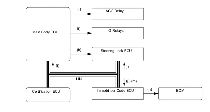
Step System Operation (o) After checking that the steering is in the unlocked condition, the main body ECU transmits a starter request (STSW) signal to the ECM. (p) The ECM receives this signal, outputs an starter relay (STAR) signal, and actuates the starter. (q) The ECM and main body ECU both output the starter relay signal in order to actuate the starter. Both the ECM and main body ECU output the signal in order to prevent situations where the starter may fail to operate, such as when the battery voltage supplied to the ECM is low. (r) When the ECM judges from the engine speed that engine start is completed, it stops the starter relay (STAR) signal, and stops the starter. (s) The main body ECU receives this signal, checks that engine start is completed, and turns OFF the indicator light of the engine switch. 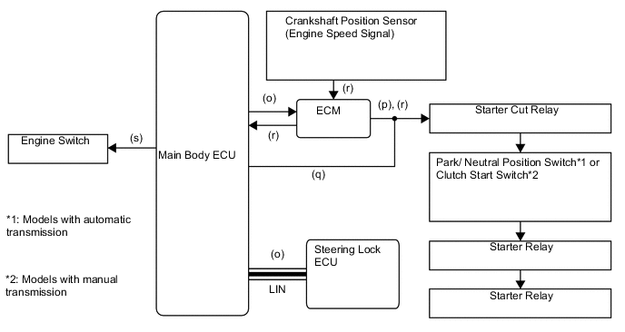
-
-
Pattern B: OFF → ACC → IG-ON → OFF
-
OFF → ACC
Step System Operation (a) The driver has the key in their possession and enters the vehicle. (b) When the driver presses the engine switch once with the following conditions satisfied, the main body ECU recognizes the engine switch signal and transmits the key certification request to the certification ECU.
-
Shift position is P.*1
-
Brake pedal is not depressed.*1
-
Clutch pedal is not depressed. *2
-
Engine switch is OFF.
(c) Due to the brake pedal*1 or the clutch pedal*2 not being depressed, the main body ECU will turn ON the amber indicator light in the engine switch. (d) The rest of the system operation is the same as (d) to (h) in pattern A. *1: Models with automatic transmission
*2: Models with manual transmission
-
-
ACC → IG-ON
Step System Operation (a) When the engine switch is at ACC and the driver pressed the engine switch again, the main body ECU recognizes the engine switch signal and turns ON the IG relays. (b) The rest of the system operation is the same as (j) to (n) in pattern A. -
IG-ON → OFF
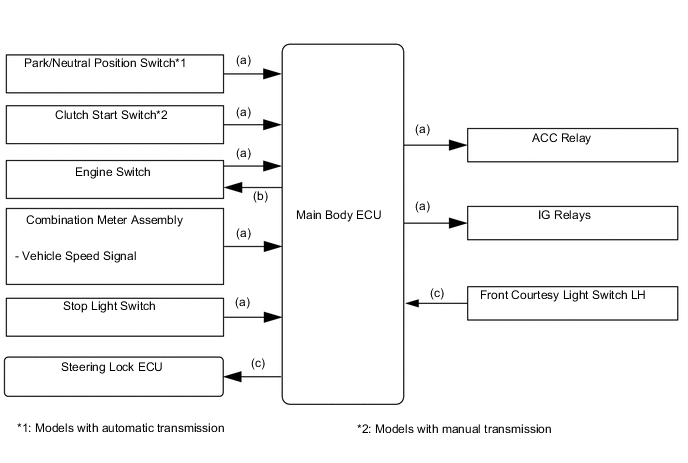
Step System Operation (a) When the engine switch is pressed once with the following conditions satisfied, the main body ECU recognizes the engine switch signal and turns OFF the ACC, IG relays.
-
Shift position is P.*1
-
Brake pedal is not depressed.*1
-
Clutch pedal is not depressed. *2
-
Vehicle speed is 0 km/h (0 mph).
-
Engine switch is OFF.
(b) When the engine switch is switched from IG-ON to OFF, the main body ECU will turn OFF the indicator light in the engine switch. (c) If the driver's door is opened, the main body ECU receives a signal from the front courtesy light switch LH. Then, the power supply to the steering lock ECU stops in order to lock the steering. *1: Models with automatic transmission
*2: Models with manual transmission
-
-
-
Pattern C: OFF → ACC → IG ON → ACC
Step System Operation (a) The system operations for the engine switch "OFF → ACC → IG-ON" are the same as those in pattern B. (b) When the engine switch is pressed once with the following conditions satisfied, the main body ECU recognizes the engine switch signal and turns OFF the IG relays.
-
Shift position is in any position except P.
-
Brake pedal is not depressed.
-
Vehicle speed is 0 km/h (0 mph).
-
Engine switch is in IG-ON mode.
(c) Even after the engine switch switches from IG-ON to ACC, the indicator light in the engine switch will remain illuminated in amber. 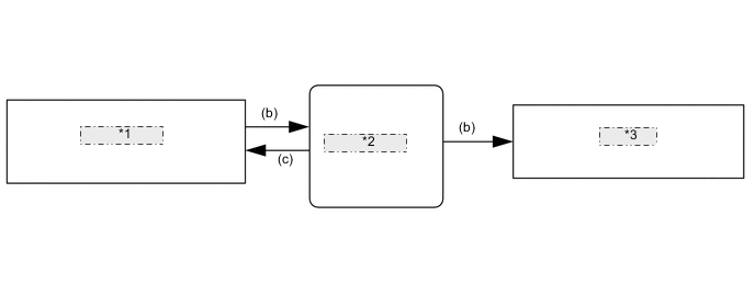
*1 Engine Switch *2 Main Body ECU *3 IG Relays -
-
Pattern D: IG-ON → OFF
-
This system operation is the same as IG-ON → OFF for pattern B.
-
-
Pattern E: IG-ON → ACC
-
This system operation is the same as pattern C. However, the indicator light of the engine switch will illuminate as follows:
-
When the engine switch is switched from IG-ON to ACC, the main body ECU makes the amber indicator light of the engine switch continue to illuminate.
-
When the engine switch is switched from engine running to OFF, the main body ECU turns OFF the indicator light of the engine switch.
-
-
-
When key battery is low
Step System Operation (a) To operate the entry and start system when the key battery is low, hold the key against the engine switch as shown in the illustration while depressing the brake pedal. (b) The main body ECU receives the stop light switch signal and transmits a key certification request signal to the certification ECU. (c) The certification ECU does not receive an ID code response from the tuner, so it actuates the transponder key amplifier built into the engine switch. (d) The transponder key amplifier outputs an engine immobiliser radio wave to the key. (e) The key receives the radio wave, and returns a radio wave response to the transponder key amplifier. (f) The transponder key amplifier combines the key ID codes with the radio wave response, and transmits it to the certification ECU. (g) The certification ECU judges and verifies the ID code, and transmits a key certification OK signal to the main body ECU. The buzzer in the combination meter assembly sounds at the same time. (h) After the buzzer sounds, if the engine switch is pressed within ten seconds while the brake pedal*1 or clutch pedal*2 is depressed, the power source switches to start the engine running, the same way as with normal entry and start system operation. (i) After the buzzer sounds, if the engine switch is pressed within ten seconds while the brake pedal is not depressed, the power source will be switched to ACC or IG-ON, the same as with normal condition. *1: Models with manual transmission
*2: Models with automatic transmission
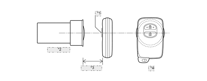
*1 TOYOTA Mark *2 Engine Switch *3 Within 10 mm *4 Key 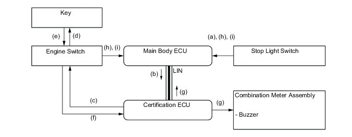
-
-
Diagnosis
-
The main body ECU and certification ECU can detect malfunctions in the entry and start system when the engine switch is in the IG-ON mode.
-
When the ECUs detect a malfunction, the amber indicator light in the engine switch flashes to warn the driver. At the same time, the ECUs store 5-digit DTC (Diagnostic Trouble Code) in their memories.
-
The indicator light warning continues for 15 seconds even after the engine switch is switched to OFF.
-
The DTC can be read by connecting the Global TechStream (GTS) to the DLC3.
-
The entry and start system may not operate successfully if a malfunction occurs.
-
-