TOYOTA PARKING ASSIST-SENSOR SYSTEM
-
CONSTRUCTION AND OPERATION
-
Ultrasonic Sensor
-
The ultrasonic sensor consists of the microphone that transmits and receives ultrasonic wave and circuit portion.
-
The circuit portion is filled with silicone or urethane to prevent water from entering.
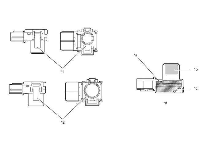
*1 Ultrasonic Sensor (Front Corner LH and RH) *2 Ultrasonic Sensor (Rear Corner LH and RH) *a Circuit Portion *b Microphone *c Urethane *d Cross Section 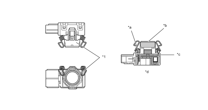
*1 Ultrasonic Sensor (Rear Center LH and RH) - - *a Circuit Portion *b Microphone *c Silicone *d Cross Section
-
-
Clearance Warning Buzzer
-
Depending on the detection distance and the detection area, the sound pattern of the clearance warning buzzer will vary.
Detection Area Detection Distance [cm (in.)] Buzzer Sound Pattern ON/ OFF Time (msec.) Front Corner Long 60 +/- 6 to 47.5 +/- 5 (23.6 +/- 2.4 to 18.7 +/- 2) 150 / 150 Middle 47.5 +/- 5 to 35 +/- 4 (18.7 +/- 2 to 13.8 +/- 1.6) 75 / 75 Short 35 +/- 4 or less (13.8 +/- 1.6 or less) Continuous Sound Rear Corner Long 60 +/- 6 to 37.5 +/- 4 (23.6 +/- 2.4 to 14.8 +/- 1.6) 150 / 150 Middle 37.5 +/- 4 to 30 +/- 3 (14.8 +/- 1.6 to 12 +/- 1.2) 75 / 75 Short 30 +/- 3 or less (12 +/- 1.2 or less) Continuous Sound Rear Center Longest 150 +/- 15 to 60 +/- 6 (59 +/- 5.9 to 23.6 +/- 2.4) 150 / 650 Long 60 +/- 6 to 45 +/- 5 (23.6 +/- 2.4 to 17.7 +/- 2) 150 / 150 Middle 45 +/- 5 to 35 +/- 4 (17.7 +/- 2 to 13.8 +/- 1.6) 75 / 75 Short 35 +/- 4 or less (13.8 +/- 1.6 or less) Continuous Sound -
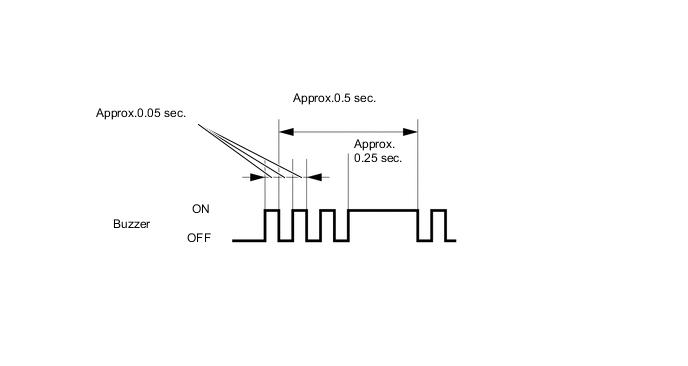
When the front and rear sensors detect obstacles at the same time, the buzzer sounds as follows.
Rear / Front Short Middle Long Not Detected Short Buzzer Timing 2 Buzzer Timing 1 Buzzer Timing 1 Continues Sound Middle Buzzer Timing 1 75/ 75 75/ 75 75/ 75 Long Buzzer Timing 1 75/ 75 150/ 150 150/ 150 Longest Buzzer Timing 1 75/ 75 150/ 150 400/ 400 Not Detected Continues Sound 75/ 75 150/ 150 None Figure 1. Buzzer Timing 1
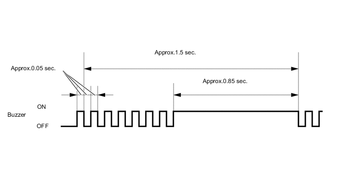
Figure 2. Buzzer Timing 2
-
-
Multi-information Display
-
The items displayed by the multi-information display are the location of the obstacle, the approximate distance between the vehicle and the obstacle, and warning messages relating to sensor malfunction, sensor freezing, or presence of dirt on the sensor. When any warning messages are displayed, the master warning light illuminates and the clearance warning buzzer sounds.
-
The number of lines shown on the display changes based on the actual distance and flashes when the distance is short.
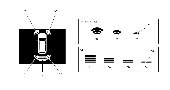
*1 Front Corner Sensor LH *2 Front Corner Sensor RH *3 Rear Corner Sensor LH *4 Rear Center Sensor *5 Rear Corner Sensor RH - - *a Long (Yellow) *b Middle (Yellow) *c Short (Red) *d Flashes *e Longest (Yellow) - - 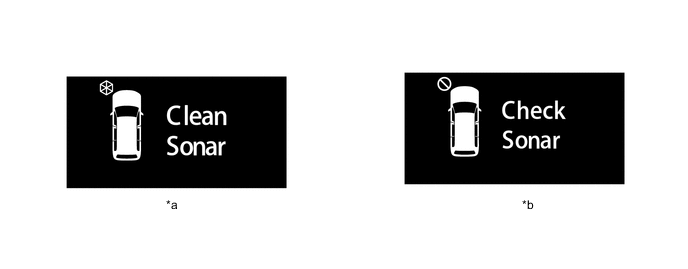
*a Frozen/Dirty *b Malfunctioning
-
-
Multi Display
-
The items displayed by the multi-display are the location of the obstacle and the approximate distance between the vehicle and the obstacle, warning messages relating to sensor malfunction, sensor freezing, or presence of dirt on the sensor. When any warning messages are displayed, the master warning light illuminates and the clearance warning buzzer sounds.
-
The distance is displayed by the number of lines and color based on the actual distance. The display usually illuminates in yellow. When the distance is short, it illuminates in red.
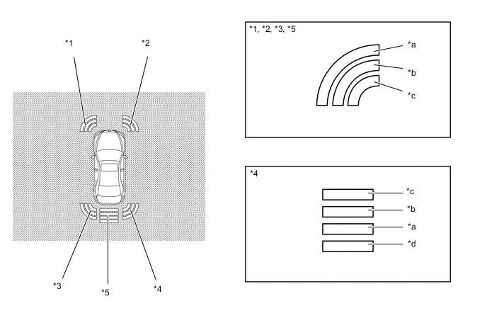
*1 Front Corner Sensor LH *2 Front Corner Sensor RH *3 Rear Corner Sensor LH *4 Rear Center Sensor *5 Rear Corner Sensor RH - - *a Long (Yellow) *b Middle (Yellow) *c Short (Red) *d Longest (Yellow) Figure 3. Warning Message
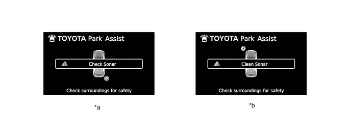
*a Ultrasonic Sensor Malfunction Warning *b Ultrasonic Sensor Freeze/Contamination Warning -
The display timing and detection distance on the multi-display can be customized.

-
-