AIR CONDITIONING
-
GENERAL
-
The air conditioning system has the following controls.
Control Outline Neural Network Control This control is capable of effecting complex control by artificially simulating the information processing method of the nervous system of living organisms in order to establish a complex input/output relationship that is similar to a human brain. Pollen Removal Mode Control Activated by the pollen removal mode switch operation. Switches the air vent to the FACE mode. Sends air which has passed through the clean air filter to the area around the upper part of the bodies of the driver and front passenger. This air is filtered by the clean air filter in order to remove pollen. Outlet Air Temperature Control Based on the temperature set at the temperature control switch, the neural network control calculates the outlet air temperature based on the input signals from various sensors. The temperature settings for the driver, front passenger, rear passengers are controlled independently in order to provide separate vehicle interior temperatures for the right and left sides of the cabin. Thus, air conditioning that accommodates the occupants' preferences has been realized. Blower Control Controls the blower motor in accordance with the airflow volume that has been calculated by the neural network control based on the input signals from various sensors. Air Outlet Control Automatically switches the air outlets in accordance with the outlet mode that has been calculated by the neural network control based on the input signals from various sensors. In accordance with the engine coolant temperature, outside air temperature, amount of sunlight, required blower, outlet temperature, and vehicle speed conditions, this control automatically switches the blower outlet to FOOT / DEF mode to prevent the windows from becoming fogged when the outside air temperature is low. Air Inlet Control Automatically controls the air inlet control damper to achieve the calculated required outlet air temperature. Drives the servo motor (for air inlet) according to the operation of the air inlet control switch and moves the dampers to the FRESH or RECIRC position. Compressor Control The air conditioning amplifier assembly compares the A/C pulley speed signals, which are transmitted by the lock sensor located on the A/C compressor, with the engine speed signals, which are transmitted by the ECM (crankshaft position sensor). When the air conditioning amplifier assembly determines that the A/C pulley is locked, it turns off the magnetic clutch and the indicator light in the A/C switch simultaneously blinks, thus alerting the driver. PTC Heater Control When the power source is ON, and the blower motor is turned ON, the air conditioning amplifier assembly turns ON the PTC heater assembly if the conditions listed below are met.
-
Engine coolant temperature is below specified temperature.
-
Ambient temperature is below specified temperature.
-
Tentative air mix damper opening angle is above the specified value (MAX HOT).
Rear Window Defogger Control Switches the rear defogger and outside rear view mirror heaters on for 15 minutes when the rear defogger button is pressed. Switches them off if the button is pressed again while they are operating. Ambient Temperature Indication Control Calculates the ambient temperature using signals transmitted by the ambient temperature sensor. Calculated values are corrected by the air conditioning amplifier assembly and then indicated on the multi-information display and the heater control panel. Viscous with Magnet Clutch Heater Assembly Control The viscous with magnet clutch heater assembly increases the engine coolant temperature by utilizing the shear heat of the silicone oil and by increasing the engine load. Self-Diagnosis A DTC (Diagnostic Trouble Code) is stored in the memory when the air conditioning amplifier assembly detects a problem with the air conditioning system. -
-
-
NEURAL NETWORK CONTROL
-
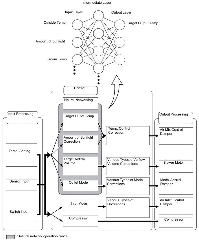
In previous automatic air conditioning systems, the air conditioning amplifier assembly determined the required outlet air temperature and blower air volume in accordance with the calculation formula that has been obtained based on information received from the sensors. However, because the senses of a person are rather complex, a given temperature is sensed differently, depending on the environment in which the person is situated. For example, a given amount of solar radiation can feel comfortably warm in a cold climate, or extremely uncomfortable in a hot climate. Therefore, as a technique for effecting a higher level of control, a neural network is used in the automatic air conditioning system. With this technique, the data that has been collected under varying environmental conditions is stored in the air conditioning amplifier assembly. The air conditioning amplifier assembly can then effect control to provide enhanced air conditioning comfort.
-
The neural network control consists of neurons in the input layer, intermediate layer, and output layer.The input layer neurons process the input data of the ambient temperature, the amount of sunlight, and the room temperature based on the outputs of the switches and sensors, and output them to the intermediate layer neurons. Based on this data, the intermediate layer neurons adjust the strength of the links among the neurons. The sum of these is then calculated by the output layer neurons in the form of the required outlet temperature, solar correction, target airflow volume, and outlet mode control volume. Accordingly, the air conditioning amplifier assembly controls the servo motors and blower motor in accordance with the control volumes that have been calculated by the neural network control.
-
-
POLLEN REMOVAL MODE CONTROL
-
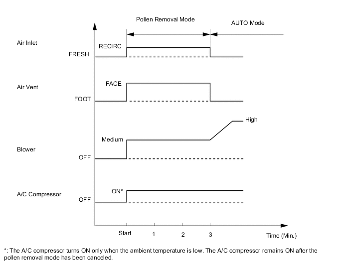
When the pollen removal switch is pressed, the pollen removal mode control is activated. Then, the air vent is switched to the FACE mode and recirculated pollen-free air flows in the area around the upper part of the bodies of the driver and front passenger.
-
When the pollen removal switch signal is input to the air conditioning amplifier assembly, the air conditioning amplifier assembly controls the A/C compressor, air inlet servo motor, air vent servo motor and blower motor as shown in the timing chart below.
-
This control usually operates for approximately 3 minutes. However, when the ambient temperature is low (5 °C maximum), it will operate for approximately 1 minute.
-
After this control stops operating, the air conditioning amplifier assembly automatically returns to the mode it was in just before the pollen removal switch was pressed.
Figure 1. Sample Timing Chart
-
-
-
VISCOUS TYPE POWER HEATER CONTROL
-
The viscous with magnet clutch heater assembly, which is located on top of the engine, is driven by a drive belt. Pressing the viscous with magnet clutch heater assembly switch provided in the instrument panel engages the magnetic clutch, causing the rotor in the viscous with magnet clutch heater assembly to rotate and the silicon oil to mix. The shear heat that is thus generated heats the coolant.
-
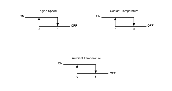
The viscous with magnet clutch heater assembly is controlled in accordance with the engine speed, coolant temperature and ambient temperature as described below. While the power heater is engaged, the engine idling speed is raised to a predetermined value whenever the shift lever is in the N or D position.
-
-
DIAGNOSIS
-
The air conditioning amplifier assembly has a self-diagnosis function. It stores any operation failures in the air conditioning system memory in the form of DTC (Diagnostic Trouble Code).
-
There are two methods for reading a DTC. One is to use a Global TechStream (GTS), and the other is to read a DTC indicated on the driver side set temperature display on the heater control panel.
-
For details, refer to the Repair Manual.
-