AIR CONDITIONING
-
AIR CONDITIONING CONTROL PANEL
-
General
-
A push-button type heater control panel is used. There are two types of control panels, one with and one without the multi display.
-
The air conditioning control assembly is located behind the center console panel.
-
-
Heater Control Panel
-
On models without the multi-display, the air conditioning status is displayed on an LCD (Liquid Crystal Display) panel.
-
Furthermore, the set temperatures for the driver seat and front passenger seat and ambient temperature are displayed on VFD (Vacuum Fluorescent Display) panel below the multi display.
-
Along with the use of the right/left independent temperature control, the temperature control switches for the driver and the front passenger have been located closer to the respective seats to enhance their ease of use.
-
The set temperature and blower level for the rear seat can be changed by pressing the REAR switch on the heater control panel.
Figure 1. Models without Multi Display
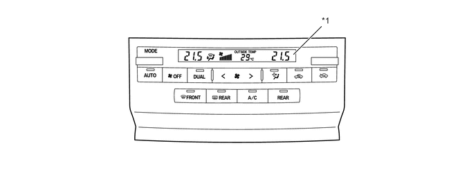
*1 Liquid Crystal Display (LCD) Panel - - Figure 2. Models with Multi Display
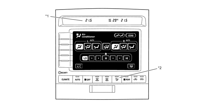
*1 VFD (Vacuum Fluorescent Display) Panel *2 Pollen Removal Mode Switch
-
-
Air Conditioning Control Assembly
-
The set temperatures for both seats and the operation mode for the rear air conditioning can be adjusted by individually operating the switches arranged on the air conditioning control assembly located behind the center console.
-
The set temperatures for both seats and the operation mode for the rear air conditioning can be adjusted by individually operating the switches arranged on the air conditioning control assembly located behind the center console.
-
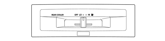
On all models with the rear cooler unit, the blow volume can be adjusted by moving the lever left and right.
Figure 3. Models with Rear Air Conditioning Unit
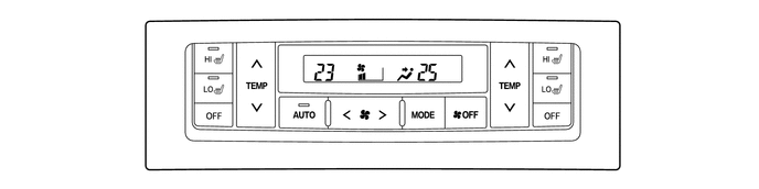
Figure 4. Models with Rear Cooler Unit
-
-
-
AIR CONDITIONING UNIT
-
Front Air Conditioning Unit
-
A semi-center location air conditioning unit, in which the evaporator and heater core are placed in the vehicle's longitudinal direction, is used. As a result, the air conditioning unit has been made compact and lightweight.
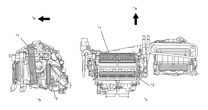
*1 Evaporator *2 Heater Radiator Unit *a Front *b Side View *c Top View - -
-
-
Heater Radiator Unit
-
A compact, lightweight, and highly efficient SFA (Straight Flow Aluminum)-II type heater radiator unit is used.

-
-
Evaporator
-
A revolutionary super-slim structure evaporator is used.
-
By placing the tanks at the top and the bottom of the evaporator unit and adopting a micropore tube construction, the following effects have been realized:
-
The heat exchanging efficiency has been improved.
-
The temperature distribution has been made more uniform.
-
The evaporator has been made thinner. 90 mm (3.5 in.) x 50 mm (1.9 in.)
-
-
The evaporator body has been coated with a type of resin is capable of preventing the growth of various bacteria which can produce a bad odor which can stick to the evaporator surfaces. The substrate for this coating material includes a chromate-free layer for environmental protection.
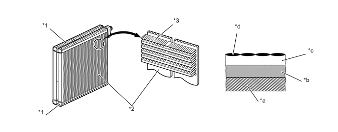
*1 Tank *2 Micropore Tube *3 Cooling Fin - - *a Aluminum Matrix *b Chromate Free Layer *c Base Resin Layer *d Hydrophile Resin
-
-
Evaporator Temperature Sensor
-
Evaporator temperature sensor detects the temperature of the cooling fin immediately past the evaporator in the form of resistance changes, and outputs it to the air conditioning amplifier assembly.
-
-
Blower Motor
-
The blower motor has an in-built blower controller, and is controlled with the duty control from the air conditioning amplifier assembly.
-
-
Air Mix Control Door
-
A compact rotary air mix door has been provided.
-
This door is independently arranged on both the left and right sides of the front air conditioning unit, moreover, 2 sets of doors are individually arranged on the warm and cold air sides. Unlike the conventional open/close type damper, all doors are designed to be openable and closable while rotating, thereby minimizing the operational space and making the front air conditioning unit more compact.
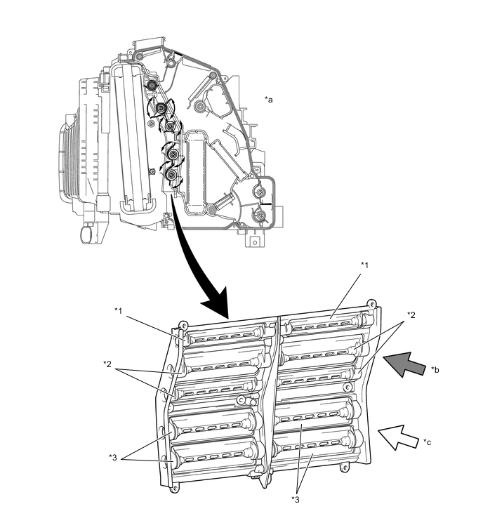
*1 Cool Air Bypass Door *2 Cool Air Side Doors *3 Warm Air Side Door - - *a Inside Cabin *b Cool Air Side *c Warm Air Side - -
-
-
PTC Heater
-
The PTC heater assembly is located above the heater core in the air conditioning unit.
-
The PTC heater consists of a PTC element, aluminum fin, and brass plate. When current is applied to the PTC element, it generates that to warm the air that passes through the unit.
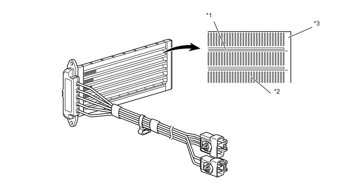
*1 PTC Element *2 Aluminum Fin *3 Brass Plate - -
-
-
Bus Connector
-
A BUS connector is used in the wire harness connection that connects the servo motor from the air conditioning amplifier assembly.
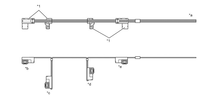
*1 BUS Connector - - *a To Air Conditioning Amplifier Assembly *b To Mode Control Servo Motor (Rear) *c To Air Mix Servo Motor (Rear LH) *d To Air Mix Servo Motor (Driver) *e To Mode Control Servo Motor (Driver) - - -
The BUS connector has a built-in communication IC which communicates with each servo motor connector, actuates the servo motor, and has a position detection function. This enables bus communication for the servo motor wire harness, for a more lightweight construction and a reduced number of wires.
Figure 5. With BUS Connector
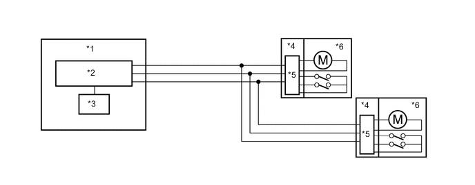
*1 Air Conditioning Amplifier Assembly *2 Communication IC *3 CPU *4 BUS Connector *5 Communication/Drive IC *6 Servo Motor
-
-
Servo Motor
-
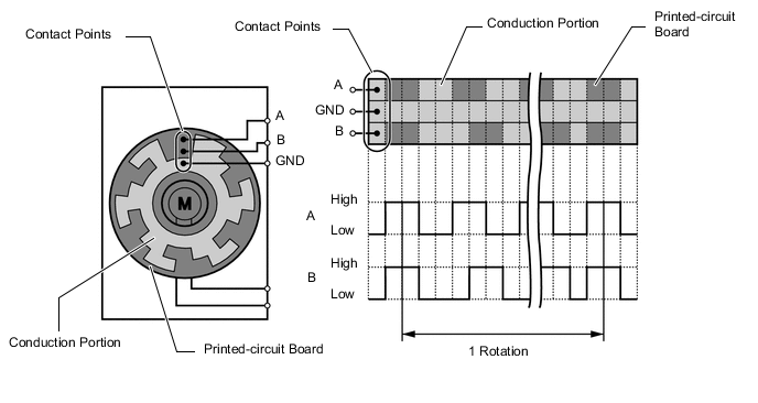
The pulse pattern type servo motor consists of a printed circuit board and servo motor. The printed circuit board has three contact points, and transmits to the air conditioning amplifier assembly two ON-OFF signals for the difference of the pulse phase. The smart connector detects the damper position and movement direction with this signal.
-
-
Clean Air Filter
-
A clean air filter (pollen removal type) is used. This filter excels in the removal of dust and pollen. The filter is made of polyester. Thus, it can be disposed of easily as a non hazardous combustible material, a feature that is provided in consideration of the environment.
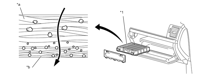
*1 Clean Air Filter - - *a Large Foreign Object Layer *b Electret Layer (Microscopic Foreign Object Filtration) Tech Tips
-
The filter should be changed at 18,000 miles (30,000 km) under normal conditions [cleaning interval: 6,000 miles (10,000 km)]. Under dusty conditions, the filter should be changed at 9,000 miles (1,5000km) [cleaning interval: 3,000 miles (5,000 km)].
-
However, observation of these guidelines should depend on the usage conditions (or environment).
-
-
-
-
REAR AIR CONDITIONING UNIT
-
The rear air conditioning unit*1/ the rear cooler unit*2 is located the left quarter trim.
-
The rear air conditioning unit*1 consists of the rear evaporator, heater core, air mix control servo motor, mode control servo motor, evaporator temperature sensor, blower controller, and rear blower motor.
-
The rear cooler unit*2 consists of the rear evaporator, blower controller and rear blower motor.
-
The evaporator and heater radiator unit are arranged horizontally to allow the airflow to be directed smoothly upward.
-
The mode control servo motor operates the laminate sliding type mode control door, and the air mix control servo motor controls the full air mix type air mix doors.
-
The evaporator has the same revolutionary super-slim structure as the front evaporator. For details regarding the evaporator, refer to the Air Conditioning Unit.
-
The heater radiator unit has the same SFA (Straight Flow Aluminum)-II type as the front heater radiator unit. For details regarding the heater radiator unit, refer to the Air Conditioning Unit.
-
Evaporator temperature sensor detects the temperature of the cool air immediately past the evaporator in the form of resistance changes, and outputs it to the air conditioning amplifier assembly.
-
As in the front air conditioning unit, the servo motor fitted to the rear air conditioning unit is connected to the air conditioning amplifier assembly with the bus connector due to the lightweight construction and a reduced number of wires. For details regarding the bus connector, refer to the Air Conditioning Unit. Furthermore, the pulse pattern type is used for the both the front and rear air conditioning units. For details regarding the servo motor, refer to the Air Conditioning Unit.
-
The porous duct excellent in sound absorption property is provided in the air inlet duct to improve quietness in the cabin. The cross section of the porous duct consists of three layers. The inner polyethyleneterephtalate layer absorbs noises produced by the air conditioning unit, the central layer eliminates the leakage of odor in the cabin and the outer felt holds the duct shape.
-
*1: Models with the multi-zone automatic climate control system
-
*2: Models with the automatic air conditioning using left/right independent temperature control
Figure 6. Rear Air Conditioning Unit
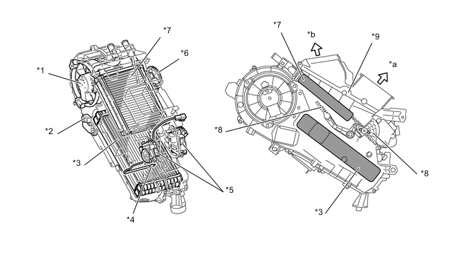
*1 Rear Blower Motor *2 Blower Motor Control *3 Rear Evaporator *4 Evaporator Temperature Sensor *5 Air Mix Servo Motor *6 Mode Control Servo Motor *7 Heater Radiator Unit *8 Air Mix Door *9 Mode Control Door (Laminate Sliding Type) - - *a Face *b Foot Figure 7. Rear Cooler Unit
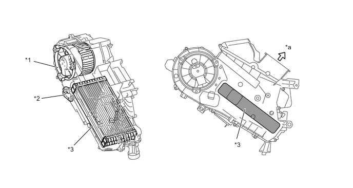
*1 Rear Blower Motor *2 Blower Motor Control *3 Rear Evaporator - - *a Face - - -
-
-
CONDENSER
-
A MF (Multi-Flow) type condenser is used. The condenser consists of two cooling portions: a condensing portion and a super-cooling portion, and gas-liquid separator (modulator) are integrated together. This condenser uses a sub-cool cycle that offers excellent heat-exchange performance.
-
In the sub-cool cycle, after the refrigerant passes through the condensing portion of the condenser, both the liquid refrigerant and the gaseous refrigerant that could not be liquefied are cooled again in the super-cooling portion. Thus, the refrigerant is sent to the evaporator in an almost completely liquefied state.
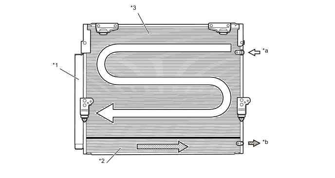
*1 Modulator *2 Super-Cooling Portion *3 Condensing Portion - - *a Gaseous Refrigerant *b Liquid Refrigerant Tech Tips
-
The point at which the air bubbles disappear in the refrigerant of the sub-cool cycle is lower than the proper amount of refrigerant with which the system must be filled. Therefore, if the system recharged with refrigerant based on the point at which the air bubbles disappear, the amount of refrigerant would be insufficient. As a result, the cooling performance of the system will be affected. If the system is overcharged with refrigerant, this will also lead to a reduced performance.
-
For the proper method of verifying the amount of the refrigerant and for instructions on how to recharge the system with refrigerant, refer to the Repair Manual.
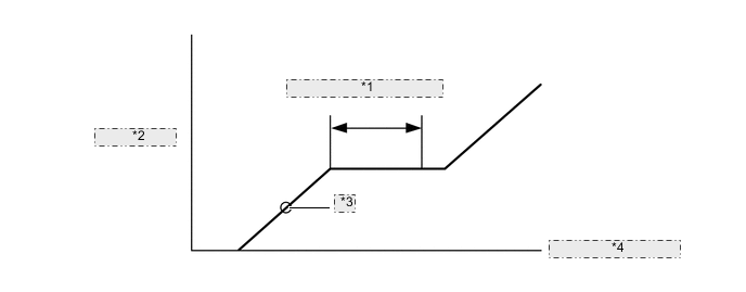
*1 Properly Recharged Amount *2 High Pressure *3 Point in which Bubbles Disappear *4 Amount of Refrigerant -
-
-
A/C COMPRESSOR
-
General
-
A 10SR19 A/C compressor has been provided, which features a compact, lightweight and low-noise design.
-
This compressor consists of magnetic clutch, shaft, swash plate, piston, shoe, rotary valve, cylinder, and lock sensor.
-
The lock sensor sends an A/C compressor speed signal to the air conditioning amplifier assembly. The air conditioning amplifier assembly compares this signal with an engine speed signal sent from the ECM. If the air conditioning amplifier assembly determines that the compressor has locked, the air conditioning amplifier assembly turns the magnetic clutch off.
-
A rotary valve, which allows refrigerant to be sucked directly into the cylinder, has been provided.
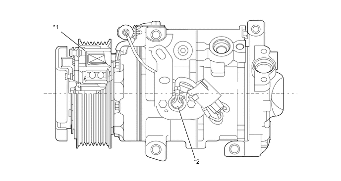
*1 Pulley with Magnetic Clutch *2 Lock Sensor
-
-
Rotary Valve
-
In order to reduce suction loss, the rotary valve has been replaced with a conventional suction valve.
-
The rotary valve is a hollow shaft, allowing refrigerant to be sucked directly into the cylinder bore through corresponding suction passages on the cylinder.
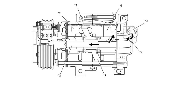
*1 Cylinder *2 Piston *3 Hollow Shaft *4 Swash Plate *5 Suction Section *6 Cylinder Bore *a Refrigerant Flow - - Figure 8. Image of Valve Operational Behavior During Suction
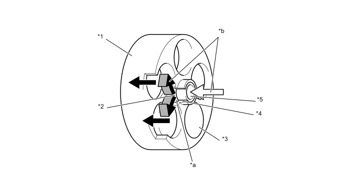
*1 Cylinder *2 Rotary Valve Suction Port *3 Cylinder Bore *4 Cylinder Suction Passage *5 Shaft - - *a The position where the rotary valve suction port and cylinder suction passage become aligned *b Refrigerant Flow
-
-
-
SUB-COOL ACCELERATOR (DOUBLERMPIPE INTERNAL HEAT EXCHANGER) SYSTEM
-
General
-
A sub-cool accelerator system has been provided. This system consists of inner and outer pipes which have been replaced with conventional refrigerant pipes (liquid and gaseous refrigerant pipes).
-
The cooling performance can be enhanced by occurring heat exchange by utilizing temperature difference of refrigerant in a refrigeration cycle and further cooling the refrigerant discharged from the condenser.
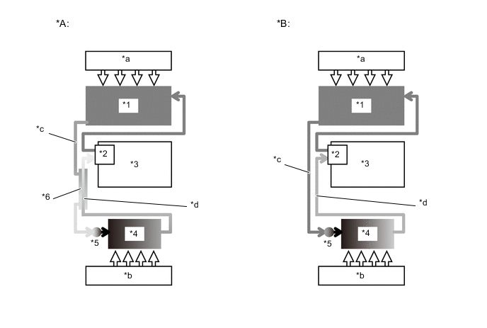
*A New Model *B Conventional *1 Condenser *2 Compressor *3 Engine *4 Evaporator *5 Expansion Valve *6 Sub-Cool Accelerator System *a Outside Air *b Inside Air *c High-Temp, High-Pressure Liquid Refrigerant *d Low-Temp, Low-Pressure Gaseous Refrigerant
-
-
Refrigerant Pipe
-
This pipe consists of inner and outer pipes, and thus heat exchange can occur by utilizing the temperature difference between low-temp, low-pressure gaseous refrigerant flowing inside the inner pipe and high-temp, high-pressure liquid refrigerant flowing between the inner and outer pipes. Furthermore, a spiral groove is formed in the pipe in order to attain further effective heat exchange.
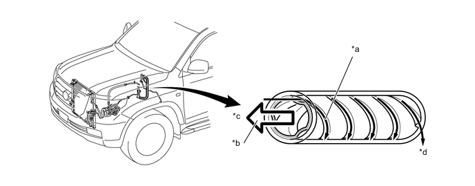
*a High-temp, High-pressure Liquid Refrigerant *b Low-temp, Low-pressure Gaseous Refrigerant *c to Compressor and Condenser *d to Evaporator
-
-
-
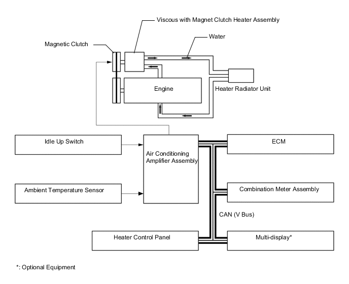
VISCOUS With MAGNET CLUTCH HEATER ASSEMBLY
-
The viscous with magnet clutch heater assembly has been provided on European diesel engine models. The power heater increases the engine coolant temperature by utilizing the shear heat of the silicone oil and by increasing the engine load.
Figure 9. System Diagram
-
-
COOLING BOX
-
General
-
The cooling box is available in the center console box as an option.
-
On the previous Land Cruiser, the cooling box employs a method of intermittent refrigerant flow control, which regulates the refrigerant flow by switching the magnetic valve ON/OFF for both the front air conditioning and cooling box evaporators, in accordance with the operational conditions of the air conditioning system and cooling box. However, on the new Land Cruiser, the cooling box employs a method of a continuous refrigerant flow control, which regulates the refrigerant flow through the ejector located in the refrigerant pipes, thereby ensuring high air conditioning performance and cooling efficiency.
Figure 10. System Diagram
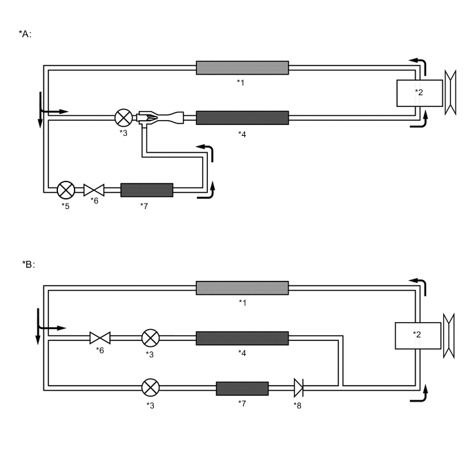
*A New Model *B Previous Model *1 Condenser *2 Compressor *3 Cooler Expansion Valve *4 Evaporator (for Front Air Conditioning Unit) *5 Fixed Squeezing Valve *6 Magnetic Valve *7 Evaporator (for Cooling Box) *8 Check Valve
-
-
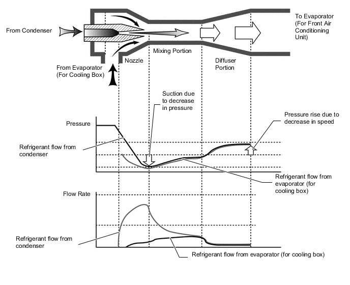
Ejector
-
The ejector includes nozzle, mixing and diffuser portions.
-
A high temperature, high pressure liquid refrigerant flowing from the condenser is guided into the mixing portion through the nozzle portion at high speed as the nozzle is inwardly tapered. This tapered nozzle allows the refrigerant pressure in the vicinity of the nozzle to decrease while guiding a low temperature, low pressure gaseous refrigerant into the nozzle portion from the evaporator (for cooling box). Thus, both refrigerants are mixed in the mixing portion and then sent to the diffuser portion.
-
As the diffuser section is outwardly flared, the refrigerant flow rate in the diffuser decreases and the refrigerant pressure rises.
-
Under this operational mechanism, the refrigerant pressure in the cooling box can be kept lower than in the front air conditioning unit even if refrigerant is continuously flowing, moreover, the refrigerant can be kept at a low temperature, thereby achieving high cooling efficiency and air conditioning performance.
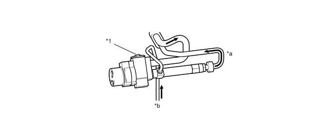
*1 Cooler Expansion Valve - - *a to Evaporator *b from Cooling Box Figure 11. Operational concept for Ejector
-
-
-
A/C PRESSURE SENSOR
-
A/C pressure sensor detects the refrigerant pressure and outputs it to the air conditioning amplifier assembly in the form of voltage changes.
-
-
ROOM TEMPERATURE SENSOR AND AMBIENT TEMPERATURE SENSOR
-
A room temperature sensor is installed on the instrument panel and right and left quarter trims.
-
The room temperature sensor detects the room temperature based on changes in the resistance of its built-in thermistor and sends a signal to the air conditioning amplifier assembly.
-
The ambient temperature sensor detects the ambient temperature based on changes in the resistance of its built-in thermistor and sends a signal to the air conditioning amplifier assembly.
-
-
AIR DUCT SENSOR
-
The air duct sensor, fitted to the air duct connected to both left and right rear heater registers, detects the air outlet temperature in accordance with the changes in the resistance of the thermistor built into the sensor and sends the signals to the air conditioning amplifier assembly.
-
-
SOLAR SENSOR
-
The solar sensor consists of a photo diode, two amplifier circuits for the front solar sensor, and frequency converter circuit for the light control sensor.
-
A solar sensor detects (in the form of changes in the current that flows through the built-in photo diode) the changes in the amount of sunlight from the LH and RH sides (2 directions) and outputs these sunlight strength signals to the air conditioning amplifier assembly.
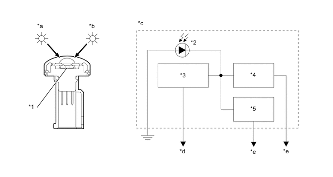
*1 Sensor Portion *2 Photo Diode *3 Frequency Convert Circuit *4 Amplifier Circuit (LH) *5 Amplifier Circuit (RH) - - *a LH Side *b RH Side *c Internal circuit of the front solar sensor *d To Main Body ECU *e To Air Conditioning Amplifier Assembly - -
-