METER
-
MULTI-INFORMATION DISPLAY
-
General
-
The multi-information display has 4 areas depending on the display mode.
Figure 1. Display Areas
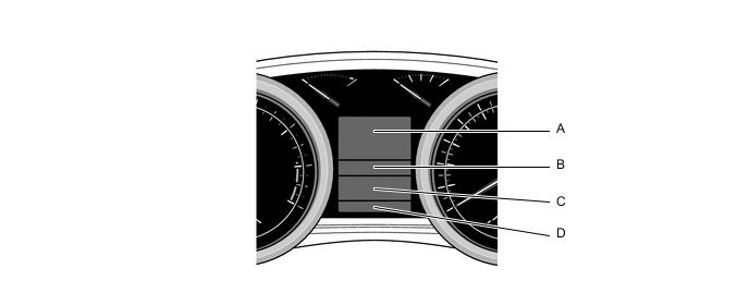
Displayed Information Display Areas Mode Outline A Cruise Information
-
8 types of information (instant fuel consumption, average fuel consumption after refueling, driving range, average fuel consumption, average speed since engine start, distance driven since engine start) can be displayed.
-
The display can be switched by using the DISPswitch.
Dynamic Radar Cruise Control Displays the set vehicle speed and control conditions of the dynamic radar cruise control. Warning Interrupts the multi-information display immediately when a warning occurs. Turn by Turn Displays the location of an obstacle and the approximate distance between the vehicle and the obstacle. Multi-terrain Select Shows the selection display of the multi-terrain select. Diagnosis Diagnostic Trouble Code (DTC) for the brake control system (TRC and VSC function), tire pressure warning system and VGRS can be displayed. B Multi-terrain Select Shows the conditions of the multi-terrain select. Crawl Control Shows the operation conditions of the crawl control. C Shift Position Displays the current shift position. Active Height Control Suspension Displays the currently selected vehicle height. D ODO/TRIP Switches the display of the ODO/TRIP and displays the ODO/TRIP. -
-
-
Flow of The Multi-information Display Indication
-
The display mode shown in area A on the multi-information display can be changed as shown in the flow chart below:
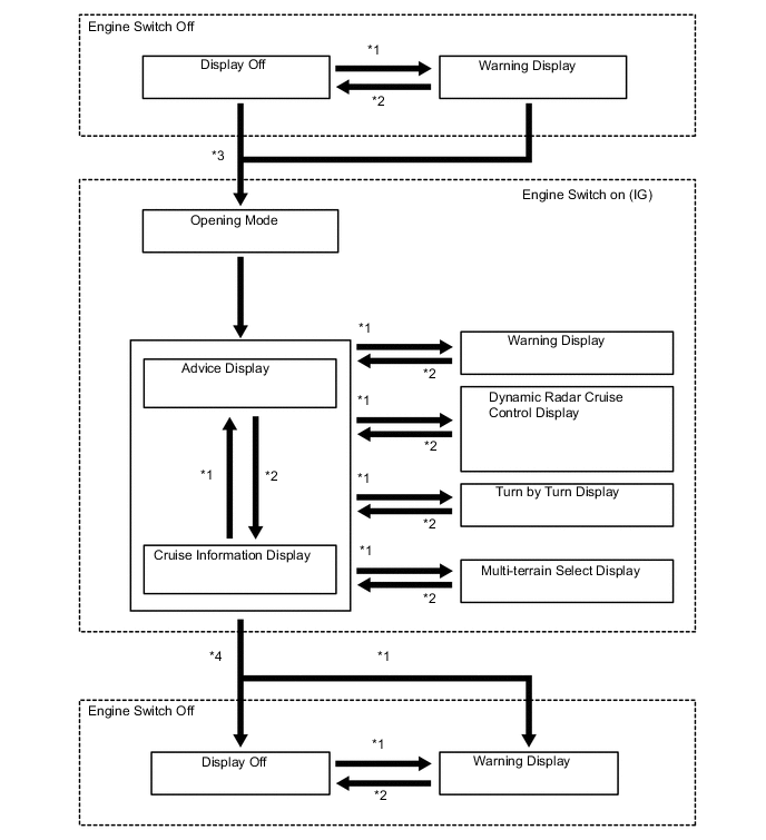
No. Condition *1 Conditions are met. *2 Conditions are not met. *3 Engine switch is turned on (IG). *4 Engine switch is turned off.
-
-
Cruise Information Mode
-
The cruise information mode is displayed on area A of the multi-information display, and the display switches in the following sequence every time the DISP switch of the steering pad switch is pressed.
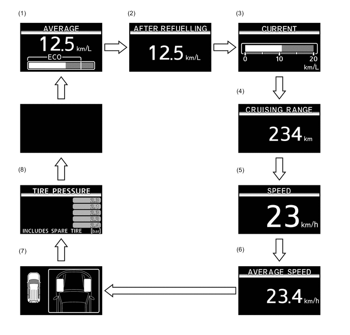
Information Outline (1)
-
Displays average fuel calculated by the combination meter based on information about the driving distance and fuel injection amount.
-
Updates every 0.5 seconds.
-
Displays Eco Drive Indicator Zone calculated by the combination meter based on the accelerator pedal opening angle and the accelerator pedal opening upper threshold level.
-
Flashes the non-eco zone display area in the Eco Drive Indicator Zone when the calculated level is considered as non-eco drive.
-
Updates every 0.2 seconds.
(2)
-
Displays the average fuel consumption after refueling calculated by the combination meter based on the driving distance and fuel consumption amount after refueling.
-
Updates every 10 seconds.
(3)
-
Displays the instantaneous fuel consumption calculated by the combination meter based on the driving distance and fuel injection amount every 20 rotations of the engine.
-
Updates every 0.5 seconds.
(4)
-
Displays the possible driving distance calculated by the combination meter based on the average fuel consumption and the rest of fuel.
-
Updates every 10 seconds.
(5) Displays the vehicle speed. (6)
-
Displays average speed calculated by the combination meter based on the driving distance and driving time after the reset operation via the ODO/TRIP switch.
-
Updates every 10 seconds.
(7) Displays the front wheel angle. (8)
-
Displays tire pressures. When the pressure of a tire is low, "LOW TIRE PRESSURE" is illuminated and the low tire pressure value is illuminated.
-
Updates every 1 seconds.
-
-
-
Warning Mode
-
General
When a warning is necessary, the warning display interrupts the multi-information display.
The master warning light may illuminate or flash and the buzzer may sound depending on the item in the multi-information display.
Display Details Master Warning Light Buzzer 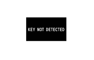
The key is not inside the vehicle. Blinks - 
The driver door is opened with the shift lever in any position other than P. Blinks - 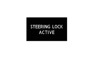
Steering lock has not been released. Blinks Sounds 
Steering lock is malfunctioning. Illuminates Sounds 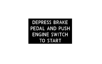
The power source is switched from OFF to ACC twice with the brake pedal released. Blinks Sounds 
Key battery is low. Illuminates - 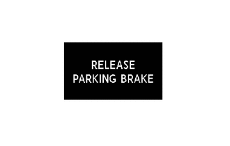
Vehicle is traveling with the parking brake engaged. Blinks - 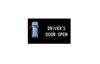
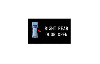
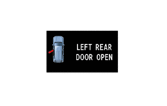
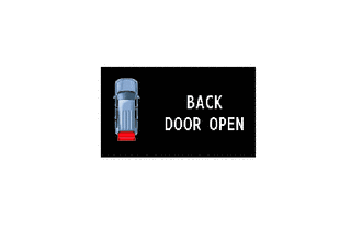
Any door is open. Blinks*1 - 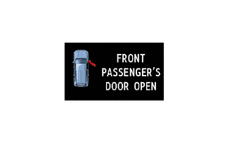

The sliding roof is open and the driver door is open. Blinks - 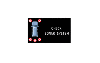
Clearance Sonar System is malfunctioning. Illuminates - 
Clearance Sonar System is dirty or covered with ice. Illuminates - 
Pre-crash safety system is malfunctioning. Illuminates Sounds 
Active height control suspension is malfunctioning. Illuminates Sounds 
Pre-crash safety system is not currently functional. - 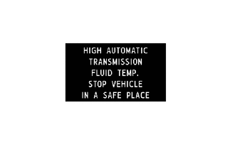
Transmission oil temperature exceeds the applicable standards. Illuminates Sounds 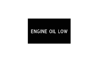
Engine oil level is low. Illuminates Sounds 
Fuel system is malfunctioning. Illuminates Sounds 
Fuel level is low. - - 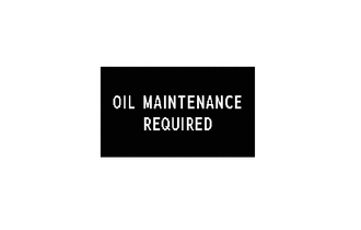
Engine oil is exchange timing.*2 - - 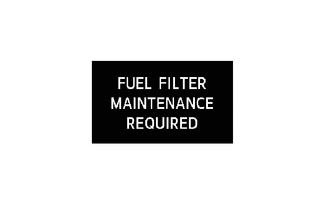
Fuel filter clogging is detected. Illuminates Sounds 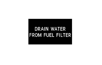
Some moisture has been detected in the fuel filter.*3 Illuminates Sounds 
A braking or reminder request is made by the pre-crash safety system. - - 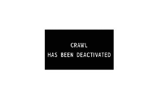
Crawl control is cancel. Illuminates - 
Turn assist function is cancel. Illuminates - 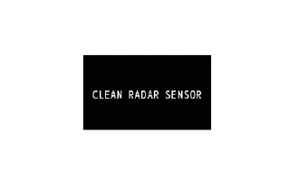
Dirt is detected on the millimeter wave radar sensor. Illuminates - 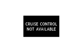
Dynamic radar cruise control system is not currently functional. Illuminates - 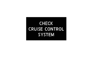
Dynamic radar cruise control system is malfunctioning. Illuminates - 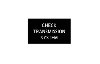
Transmission control system is malfunction. Illuminates Sounds 
VGRS system is malfunctioning. Illuminates Sounds 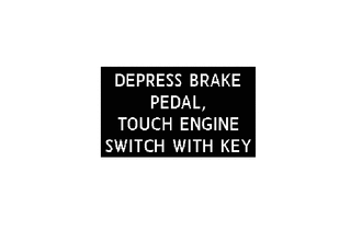
The key cannot be identified. Blinks - 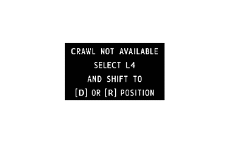
Control is started when CRAWL control start conditions cannot be met. - - 
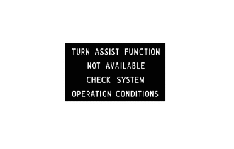
Turn assist function is cancel. - - 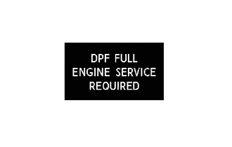
DPF cannot be automatically started.*4 Illuminates - 
Traction control is off. - - 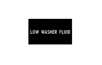
Washer fluid level is low. - - 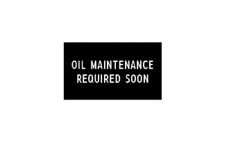
Time for engine oil replacement is close.*2 - - 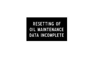
Oil maintenance reset operation has failed.*5 - - 
Theft deterrent system off. - - 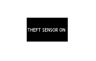
Theft deterrent system on. - - 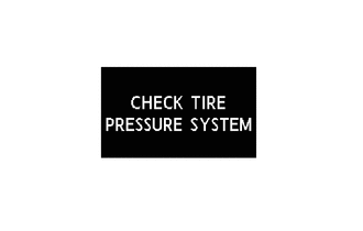
Tire pressure warning system is malfunctioning.*6 Illuminates Sounds *1: Vehicle speed is 5 km/h (3 mph) or more
*2: Models for Europe with 1VR-FTV engine
*3: Models with diesel engine
*4: Models with diesel engine in compliance with EURO 5 emission regulation
*5: Models for Europe with diesel engine
*6: Models with tire pressure warning system
-
-
-
FUEL FILTER WARNING (DIESEL ENGINE MODEL)
-
General
-
On the analog type combination meter, the fuel filter warning light illuminates when the fuel light is clogged or blinks when condensed water on the fuel filter is detected.
-
On the optitron display type combination meter, a warning message corresponding to individual warning items is indicated on the multi-information display.
-
This system is controlled by meter ECU.
Function List Fuel Filter Warning Function Analog Type Combination Meter 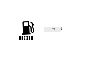
*1 Illuminate Optitron Type Combination Meter 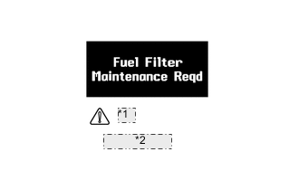
*1 Illuminate *2 Buzzer: Sound Fuel Sedimenter Warning Function Analog Type Combination Meter 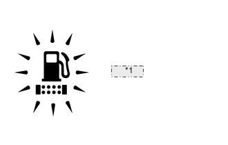
*1 Blinking Optitron Type Combination Meter 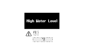
*1 Illuminate *2 Buzzer: Sound
-
-
Operation
-
Fuel Filter Warning
-
To prevent false alarms on a cold engine, the meter ECU starts its judgment function with the engine switch turned ON, after a total of 30 minutes have elapsed with the input of vehicle speed signal information (minimum vehicle speed of 2.5 km/h).
-
The fuel filter warning switch turns OFF when the vacuum in the fuel filter reaches a predetermined level.
-
When the meter ECU receives OFF signals from the fuel filter warning switch under the following conditions, it alerts the driver in accordance with the meter specifications.
-
OFF signals from the fuel filter warning switch are input continuously for 10 minutes.
-
When the engine switch is in the ON position, OFF signal (between 1 second and 10 minutes in duration) from the fuel filter warning switch is input twice with a minimum interval of 1 second.
-
-
On all models with the optitron display type combination meter, the driver is alerted by the master warning light illuminating, a warning message appearing on the "Fuel Filter Maintenance Reqd" and a buzzer.
-
On all models with the analogy type combination meter, the driver is alerted by the fuel filter warning light illuminating.
-
-
Fuel Sedimenter Warning
-
When the amount of water that has accumulated in the sedimenter reaches a predetermined level, the fuel sedimenter level switch, which is located in the bottom of the fuel filter, turns ON. The meter ECU renders this signal as a fuel sedimenter warning and then alerts the driver in accordance with the meter specifications.
-
On models with the optitron display type combination meter, the driver is alerted by the master warning light illuminating, a warning message "High Water Level" appearing on the combination meter and the buzzer sounding.
-
On models with the analogy type combination meter, the driver is alerted by the fuel filter warning light blinking and the buzzer sounding.
Tech Tips
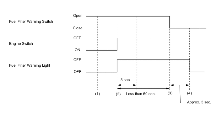
When the fuel filter warning switch detects a failure, the meter ECU stores this failure in memory, and continues to illuminate* the fuel filter warning light. Therefore, after replacing the fuel filter, the illuminationin formation stored in the meter ECU memory must be erased through the following procedure:
-
With the engine switch turned OFF, disconnect the fuel filter warning switch connector.
-
Turn the engine switch from OFF to ON.
-
After more than 3 seconds but less than 60 seconds have elapsed, reconnect the connector.
-
After approximately 3 seconds have elapsed with the fuel filter warning switch closed, the system confirms the deletion of the illumination information by turning OFF* the warning light.
*: The warning light will blink in case of a sedimenter failure.
-
-
-
-
Buzzer
-
The table below shows the warning and reminder functions of the buzzer.
Function Item Warning
-
Multi-information Display Warning Mode Indication
-
Speed Limit Warning
-
Fuel Filter Warning
-
Fuel Sedimenter Warning
Reminder
-
Key Reminder
-
Seat Belt Reminder
-
Oil Maintenance Reminder
-
-
-