MULTIPLEX COMMUNICATION
-
DESCRIPTION
-
The multiplex communication system uses the following 4 communication protocols:
-
The Controller Area Network (CAN) is used for communication between the engine, chassis, and body electrical system.
-
The Local Interconnect Network (LIN) is used for communication within the body electrical system.
-
The Audio Visual Communication-Local Area Network (AVC-LAN) is used for communication only between the Audio Visual (AV) system components.
-
The Media Orientated System Transport (MOST) is used for communication within the Audio Visual (AV) system components.
-
-
There are two types of CAN communication systems, with different communication speeds: the HS-CAN (high speed) and the MS-CAN (medium speed).
-
-
MAIN FEATURES
-
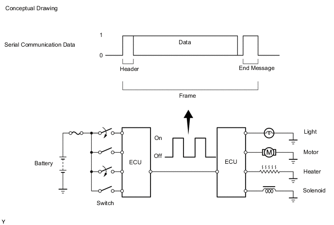
Multiplex communication uses serial communication data that consists of bits and frames in order to exchange information between the various ECUs. This allows a reduction of the amount of wiring used in the vehicle.
-
A bit is the basic unit of communication used to represent the information. A bit is represented by binary values of "0" or "1".
-
A frame is a body of data transmitted together. A frame contains a header that indicates the beginning, and an end message that indicates the end.
-
-
-
DIFFERENCES BETWEEN CAN, LIN, AVC-LAN AND MOST
-
GENERAL
-
The protocols, which are the rules for establishing data communication, differ between CAN, LIN, AVC-LAN and MOST. If the ECUs in the networks use different data frameworks such as communication speed, communication wire or signals, they will be unable to understand each other. Therefore, protocols (rules) must be established among them.
-
Compared to LIN and AVC-LAN, CAN features high-speed data transmission. Therefore, CAN is able to transmit larger amounts of data faster than other protocols. This feature makes it possible to transmit data accurately for the powertrain and chassis control systems. These systems require large amounts of data to be transmitted in short periods of time.
-
MOST is used to transmit control information, audio, video, and data in real time.
Protocol CAN (ISO Standard) LIN (LIN Consortium) AVC-LAN MOST Communication Speed 500kbps*/ HS-CAN 250kbps*/ MS-CAN (Max. 1 M bps) Max. 20 kbps* Max. 17.8 kbps Max. 50 Mbps* Communication Wire Twisted-pair Wire AV Single Wire Twisted-pair Wire Shielded Twistedpair Wire Drive Type Differential Voltage Drive Single Wire Voltage Drive Differential Voltage Drive Data Length 1-8 Byte (Variable) 2, 4, 8 Byte (Variable) 0-32 Byte (Variable) 0-128 Byte (Variable) *: bps: abbreviation for "Bits Per Second", indicating the number of bits that can be transmitted per second.
-
-
-
COMMUNICATION WIRE
-
A twisted pair of wires is used for CAN and AVC-LAN communication. A single Automobile Vinyl (AV) wire is used for LIN communication.
Communication Wire Outline Twisted-pair Wire 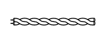
This communication wire is a pair of twisted wires. Communication is driven by applying different voltages to the 2 lines in order to send a single signal. This system, which is called a "Differential Voltage Drive", reduces noise. AV Single Wire 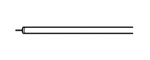
This is a lightweight single communication wire that consists of a single core line surrounded by insulation. Voltage is applied to this line in order to drive communication, and this system is called a "Single Wire Voltage Drive". Shielded Twistedpair Wire 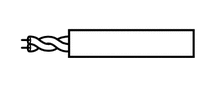
This communication wire is a shielded pair of twisted wires. Communication is driven by applying different voltages to the 2 lines in order to send a single signal. This system, which is called a "Differential Voltage Drive", reduces noise. 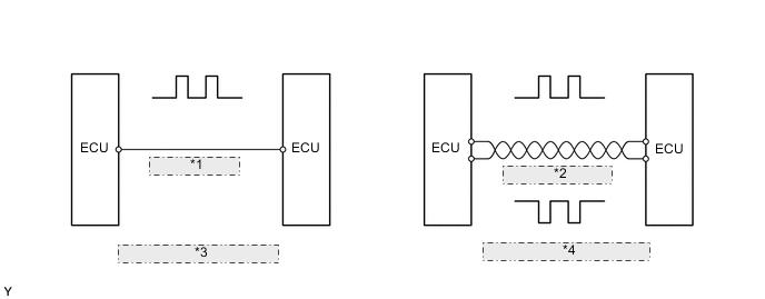
*1 AV Single Wire *2 Twisted-pair Wire *3 Single Wire Voltage Drive *4 Differential Voltage Drive
-
-
SYSTEM DIAGRAM
Figure 1. Models with Network Gateway ECU
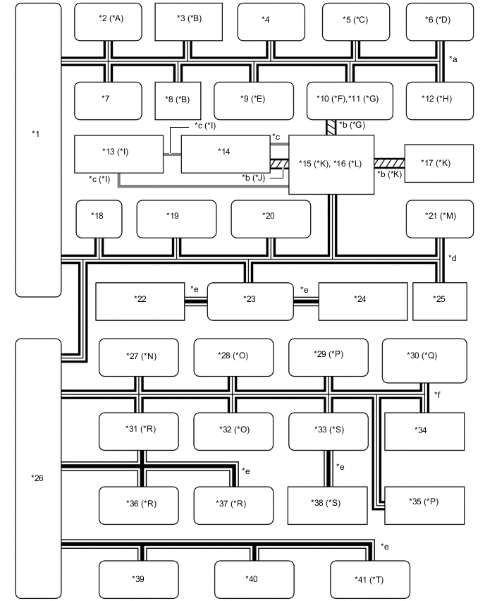
*A Models with Active Height Control System *B Models with VSC System *C Models with VGRS System *D Models with Dynamic Radar Cruise Control System *E Models with Variable Flow Control (VFC) Power Steering System *F Models with Toyota Parking Assist-sensor System and Models without Side Monitor System *G Models with Side Monitor System *H Models with Pre-crash Safety System *I Models with Rear Seat Entertainment (RSE) System *J Models with Display Audio System and Stereo Component Amplifer Assembly *K Models with Navigation System *L Models with Display Audio System *M Models with Automatic Headlight Beam Level Control System *N Models with Power Tilt and Power Telescopic Steering Column System *O Models with Seat Memory *P Models with Power Back Door System *Q Models with Tire Pressure Warning System *R Models with Entry and Start System *S Models with Rain Sensor *T Models with Double Lock System *1 Network Gateway ECU *2 Suspension Control ECU *3 Steering Angle Sensor *4 4WD Control ECU *5 Steering Control ECU *6 Distance Control ECU *7 Skid Control ECU *8 Yawrate Sensor *9 Power Steering ECU Assembly *10 Clearance Warning ECU *11 Parking Assist ECU *12 Seat Belt Control ECU *13 Television Display Assembly *14 Stereo Component Amplifier Assembly *15 Multi-media Module Receiver Assembly *16 Radio and Display Receiver Assembly *17 Multi Display *18 ECM *19 Combination Meter Assembly *20 Center Airbag Sensor Assembly *21 Headlight Leveling ECU *22 Front Heater Control Panel *23 Air Conditioning Amplifier Assembly *24 Rear Heater Control Panel *25 DLC3 *26 Main Body ECU *27 Multiplex Tilt and Telescopic ECU *28 Outer Mirror Control ECU *29 Power Back Door ECU *30 Tire Pressure Warning ECU and Receiver *31 Certification ECU *32 Driver Seat ECU *33 Windshield Wiper ECU *34 Accessory Bus Buffer *35 No. 2 Main Body ECU *36 Immobiliser Code ECU *37 Steering Lock ECU *38 Rain Sensor *39 Power Window ECU *40 Sliding Roof ECU *41 Double Lock ECU - - *a CAN (Movement Control Bus) *b AVC-LAN *c MOST *d CAN (V Bus) *e LIN *f CAN (MS Bus) Figure 2. Models without Network Gateway ECU
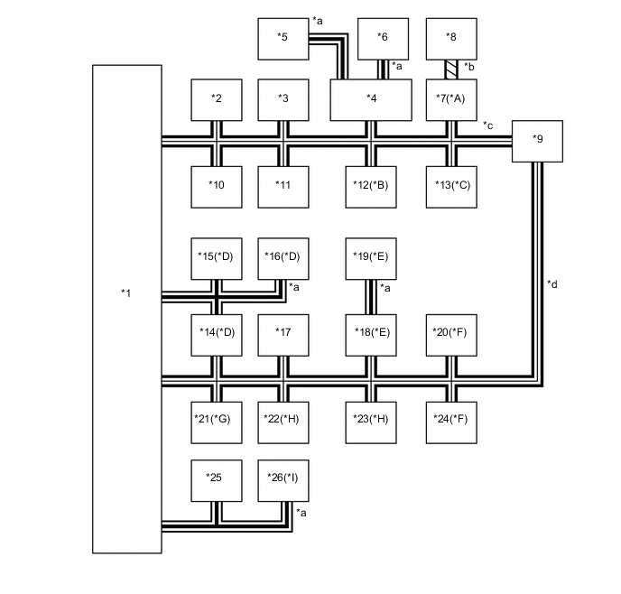
*A Models with Navigation System *B Models with SRS Airbag System *C Models with Toyota Parking Assist-sensor System and Models without Side Monitor System *D Models with Entry and Start System *E Models with Rain Sensor *F Models with Power Back Door System *G Models with Power Tilt and Power Telescopic Steering Column System *H Models with Seat Memory *I Models with Sliding Roof System - - *1 Main Body ECU *2 ECM *3 DLC3 *4 Air Conditioning Amplifier *5 Front Heater Control Panel *6 Rear Heater Control Panel *7 Multi-media Module Receiver Assembly *8 Multi Display *9 Combination Meter Assembly *10 4WD Control ECU *11 Skid Control ECU *12 Center Airbag Sensor Assembly *13 Clearance Warning ECU *14 Certification ECU *15 Immobiliser Code ECU *16 Steering Lock ECU *17 Accessory Bus Buffer *18 Windshield Wiper ECU *19 Rain Sensor *20 Power Back Door ECU *21 Multiplex Tilt and Telescopic ECU *22 Outer Mirror Control ECU *23 Driver Seat ECU *24 No. 2 Main Body ECU *25 Power Window ECU *26 Sliding Roof ECU *a LIN *b AVC-LAN *c CAN (V Bus) *d CAN (MS Bus)