STEERING
-
General
-
A manual tilt and telescopic steering column or power tilt and power telescopic steering column is provided depending on the model.
-
The intermediate shaft is equipped with a mechanism capable of controlling the length of the shaft during driving so smooth steering can be attained.
-
An energy absorbing mechanism and intermediate shaft contraction mechanism are used to ensure driver safety in the event of a collision.
-
An electrical steering lock system is used. For details, see the ENTRY AND START SYSTEM.
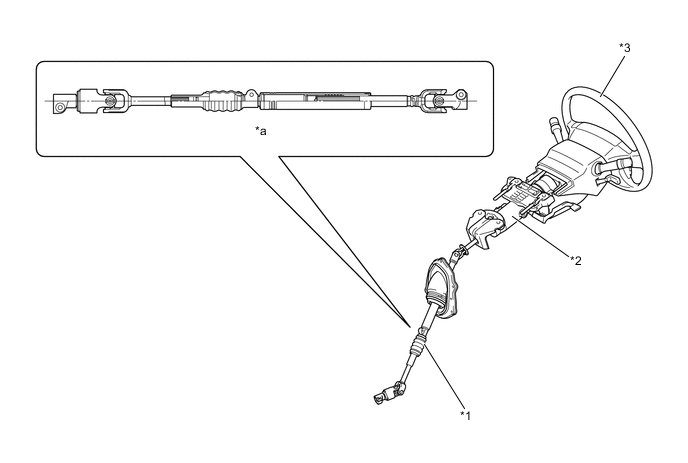
*1 Intermediate Shaft *2 Steering Column Assembly *3 Steering Wheel - - *a Intermediate Shaft Cross Section - -
-
-
Manual Tilt and Telescopic Steering Column
-
The manual tilt and telescopic mechanism allows adjustment of the steering wheel position in the vertical and longitudinal (extending and retracting) directions through lever operation. This provides the driver with the most comfortable driving position.
-
The tilt and telescopic mechanism is locked using the tilt lever and telescopic lever.
-
The tilt mechanism enables the steering column to be tilted up to 13.5° (2.25° X 6 steps), and the stepless telescopic mechanism enables the steering column to be moved up to 45 mm (1.77 in.).
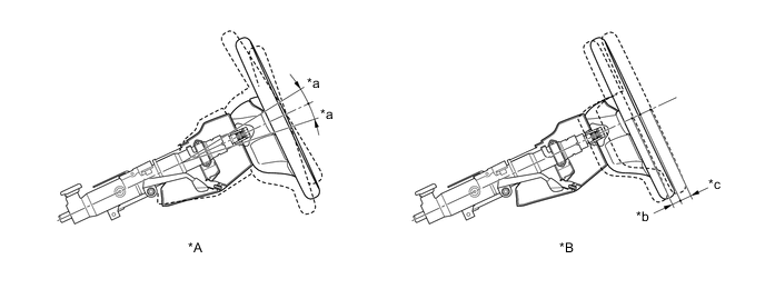
*A Tilt Mechanism *B Telescopic Mechanism *a 6.75° *b 20.0 mm (0.79 in.) *c 25.0 mm (0.98 in.) - -
-
-
-
Power Tilt and Power Telescopic Steering Column
-
General
-
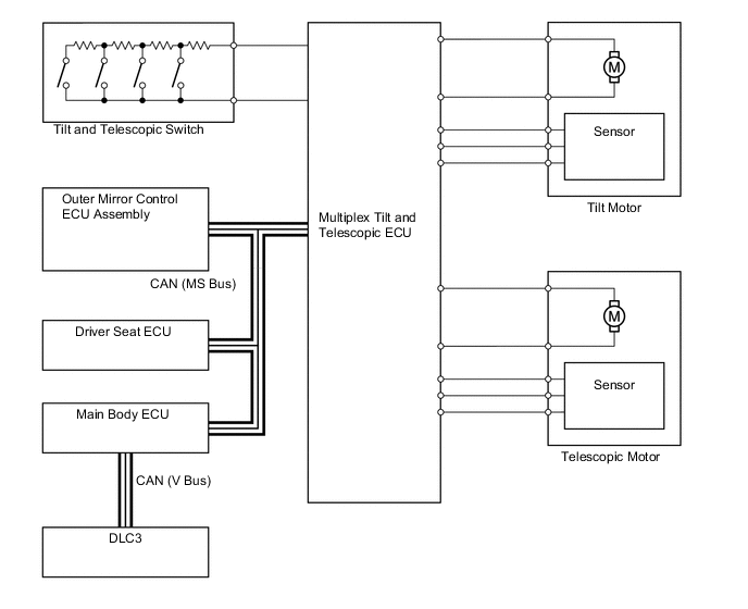
The power tilt and power telescopic steering column consists of the tilt and telescopic ECU, tilt motor and telescopic motor.
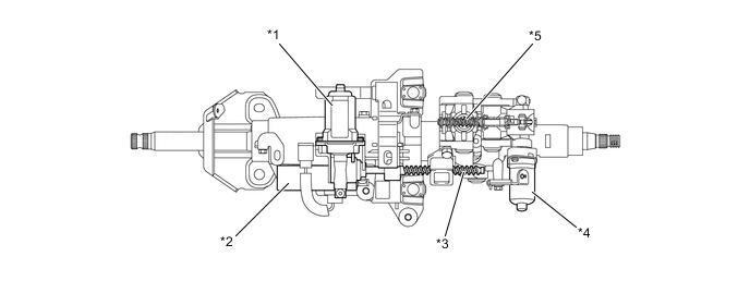
*1 Telescopic Motor
-
Motor
-
Position Sensor
*2 Multiplex Tilt and Telescopic ECU *3 Telescopic Worm Gear *4 Tilt Motor
-
Motor
-
Position Sensor
*5 Tilt Worm Gear - - Figure 1. System Diagram
-
-
-
Operation
-
Manual Operation
-
A stepless adjustment enables the tilt mechanism to be tilted 15.25° vertically, and the telescopic mechanism to be moved 45 mm (1.77 in.) longitudinally.
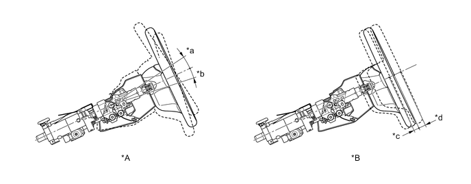
*A Tilt Mechanism *B Telescopic Mechanism *a 8.5° *b 6.75° *c 20.0 mm (0.79 in.) *d 25.0 mm (0.98 in.)
-
-
Automatic Set Function
Function Outline Auto Away When the engine switch is turned from ACC or IG-ON to OFF, the steering wheel automatically tilts up and retracts all the way for easy exit and entry. Auto Return When the engine switch is turned from OFF to ACC or IG-ON, the steering wheel automatically returns to the previous position which was set before the engine switch was turned OFF. -
Memory Function (Models with Memory System)
-
Three steering wheel positions can be memorized, allowing different positions to be restored by the memory system.
-
-
Position Detection
-
To detect the position of the tilt and telescopic steering column, position sensors that utilize hall elements are located in the tilt and telescopic motors and are used to detect the changes in the magnetic field of the magnets, which are attached to the shafts of the motors.
-
-
-
Fail-safe
-
If the multiplex tilt and telescopic ECU detects a malfunction in the power tilt and power telescopic steering column system, the ECU changes the control mode to a fail-safe mode as follows:
Detection Item Fail-safe Key Code Confirm Signal Malfunction Auto away or auto return stops. Tilt Position Sensor or Tilt Motor Circuit Malfunction Tilt operation is suspended. Telescopic Position Sensor or Telescopic Motor Circuit Malfunction Telescopic operation is suspended. ECU Power Source Circuit Malfunction Tilt and Telescopic operations are suspended. -
If a communication problem has occurred in any ECU related to the tilt and telescopic ECU and the power tilt and power telescopic steering column system, the power tilt and power telescopic steering column system allows the following controls to continue:
Control ECU in which Communication is Lost Main Body ECU Mirror ECU Driver Seat ECU Related All ECU Manual X*1 ○ ○ X*1 Auto Away X X ○ X Auto Return X*2 X*2 ○ X*2 Memory X X X X Tech Tips
*1:
-
The operation is permitted if the engine switch is ACC or IG-ON while the signal from the main body ECU is interrupting.
-
The operation is prohibited if the engine switch is OFF while the signal from the main body ECU is interrupting.
*2
-
In case that the signal from main body ECU is interrupted after the operation was started, the operation will be continued if the engine switch is ACC or IG-ON.
-
The operation is prohibited if the engine switch is OFF while the signal from main body ECU is interrupting.
-
-
-
Diagnosis
-
If the multiplex tilt and telescopic ECU detects a malfunction in the power tilt and power telescopic steering column system, the ECU stores the Diagnostic Trouble Code (DTC) in memory. Then, by a Global TechStream (GTS) to the DLC3, the DTC can be read and an active test can be performed to test the operation of the tilt motor and the telescopic motor. For details, refer to the Repair Manual.
-
-
-
Energy Absorbing Mechanism
-
The energy absorbing mechanism mainly consists of a breakaway bracket, energy absorbing plate, lower bracket, main shaft, and intermediate shaft.
-
When an impact is transmitted to the steering wheel in a collision (secondary collision), the steering wheel and the steering wheel pad help absorb the impact. In addition, the breakaway bracket and the lower bracket separate, causing the entire steering column to move forward. At this time, the energy absorbing plate becomes deformed to help absorb the impact of the secondary collision.
Figure 2. Energy Absorbing Mechanism (Before Collision)
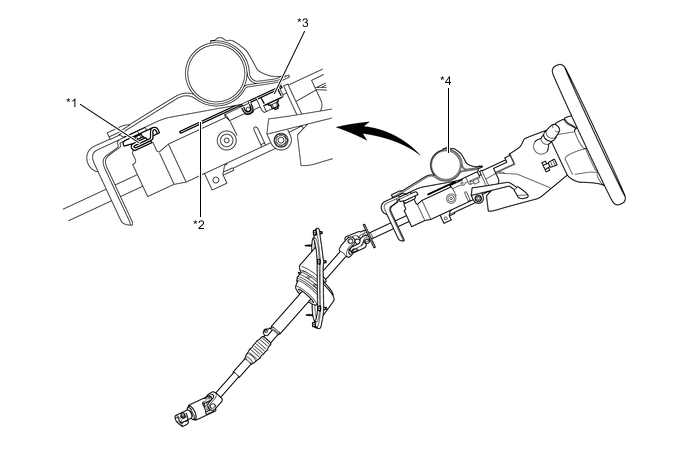
*1 Lower Bracket *2 Energy Absorbing Plate *3 Breakaway Bracket *4 Instrument Panel Reinforcement Figure 3. Energy Absorbing Mechanism (After Collision)
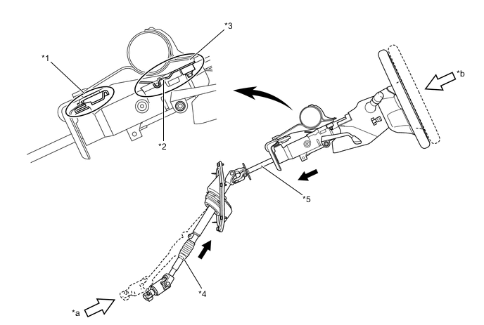
*1 Lower Bracket (Separate) *2 Energy Absorbing Plate (Deform) *3 Breakaway Bracket (Separate) *4 Intermediate shaft (Contract) *5 Main shaft (Contract) - - *a Primary Collision *b Secondary Collision
-