STEERING
-
General
-
A VGRS system is used to control the turning angle of the front wheels in accordance with the vehicle speed. As a result, excellent ease of steering operation and vehicle stability have been realized, from the low-speed to the high-speed range.
-
This system is controlled by the steering control ECU, which operates the steering actuator that is mounted on the steering intermediate shaft. The steering control ECU calculates the desired steering angle and controls the steering actuator operating angle based on the current steering angle detected by the steering angle sensor and vehicle speed.
-
-
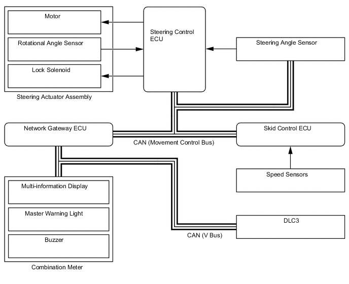
System Diagram
-
Layout of Main Components
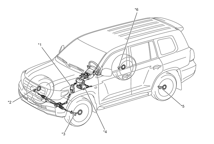
*1 Steering Actuator Assembly
-
Motor
-
Rotational Angle Sensor
-
Lock Solenoid
*2 Front Speed Sensor RH *3 Front Speed Sensor LH *4 Hydraulic Brake Booster
-
Skid Control ECU
*5 Rear Speed Sensor LH *6 Rear Speed Sensor RH 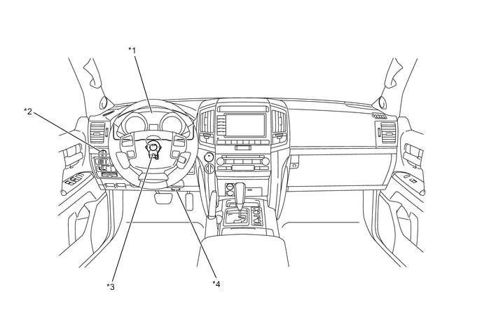
*1 Combination Meter
-
Multi-information Display
-
Master Warning Light
-
Buzzer
*2 Steering Control ECU *3 Steering Angle Sensor *4 DLC3 -
-
Function of Main Components
Components Function Steering Control ECU Operates the motor by calculating the operating angle of the steering actuator based on the signals from the steering angle sensor and speed sensor. Steering Actuator Assembly Motor Rotates to create the operating angle of the steering actuator upon receiving the signals from the steering control ECU. Rotational Angle Sensor Outputs the rotational angle of the motor to the steering control ECU. Lock Solenoid Locks the motor shaft so that the motor will not rotate in case of a system malfunction. Steering Angle Sensor Detects the steering angle of the steering wheel and transmits them to the steering control ECU. Skid Control ECU
-
Transmits the vehicle speed signal to the steering control ECU.
-
Transmits the power steering cooperative control signal to the steering control ECU.
Speed Sensors Detects the wheel speed and outputs it to the skid control ECU. Combination Meter Multi-information Display Indicates the message to inform the driver of a malfunction in the system. Master Warning Light Illuminates to warn the driver of a malfunction in the system. Buzzer Sounds to warn the driver of a malfunction in the system. -
-
Construction of Main Components
-
Steering Actuator
-
General
-
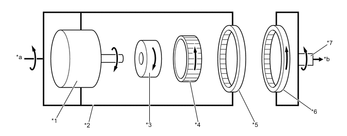
The steering actuator consists of a housing, motor, reduction mechanism, input shaft, output shaft and lock mechanism.
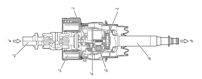
*1 Lock Mechanism *2 Input Shaft *3 Spiral Cable *4 Housing *5 Motor *6 Output Shaft *7 Reduction Mechanism - - *a From Steering Wheel *b To Steering Gear
-
-
Motor
-
A compact, high power output, and low noise brushless type motor is used. This motor is enclosed in the housing.
-
This motor mainly consists of a magnet, coil, and motor shaft. The motor shaft is coupled to the wave generator of the reduction mechanism in order to transmit the rotational movement of the motor to the reduction mechanism.
-
This motor, which is controlled by the signal from the steering control ECU, rotates either clockwise or counterclockwise, depending on the steered direction of the steering wheel.
-
The rotating direction and rotation angle of the motor are detected by the rotational angle sensor.
*1 Coil *2 Rotational Angle Sensor *3 Magnet *4 Motor Shaft *a To Reduction Mechanism (Wave Generator) - -
-
-
Reduction Mechanism
-
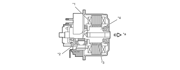
The reduction mechanism uses strain wave gearing, which is compact and highly accurate, and creates a large reduction gear ratio (1:50) using a small number of components.
-
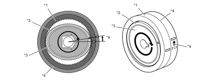
This reduction mechanism consists of a driven gear, stator gear, flexible gear, and wave generator.
*1 Stator Gear *2 Flexible Gear *3 Driven Gear *4 Wave Generator *a From Steering Wheel *b To Steering Gear Construction of Reduction Mechanism Item Construction Stator Gear (Input)
-
Has a rigid body, a ring shape, and contains 102 teeth along the inner circumference.
-
Positioned parallel with the driven gear.
-
Coupled to the housing of the steering actuator.
Driven Gear (Output)
-
Has a rigid body, a ring shape, and contains 100 teeth along the inner circumference.
-
Positioned parallel with the stator gear.
-
Coupled to the output shaft of the steering actuator.
Flexible Gear
-
Has a flexible metal body that forms a belt shape and contains 100 teeth along the outer circumference.
-
Located outside of the wave generator, and positioned in a way that its gear teeth are meshed with the inside of both stator gear and driven gear.
Wave Generator
-
Consists of an oval-shaped cam and a ball bearing that is fitted around the cam.
-
Coupled to the motor shaft of the motor, rotates inside the flexible gear while pushing the flexible gear against the stator gear and the driven gear.
-
-
Operating Principle of Reduction Mechanism
-
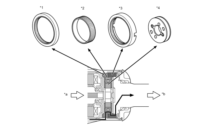
The flexible gear is fitted inside the driven gear and stator gear as illustrated. Furthermore, the wave generator is fitted inside the flexible gear. The rotational movement of the wave generator causes the flexible gear to become deformed into an oval shape. The teeth at the major axis of the oval shape meshes with the teeth of the driven gear and stator gear, and the teeth at the minor axis are disengaged.
*1 Stator Gear *2 Flexible Gear *3 Wave Generator *4 Driven Gear -
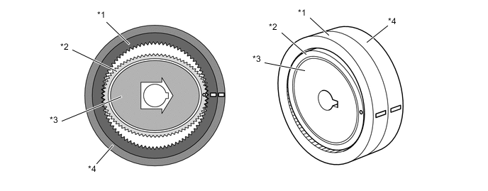
When the stator gear is fixed and the wave generator rotates clockwise, the flexible gear undergoes an elastic deformation. This causes the meshed areas between the flexible gear, driven gear and stator gear to move consecutively.
*1 Stator Gear *2 Flexible Gear *3 Wave Generator *4 Driven Gear -
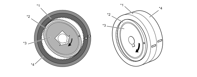
When the wave generator makes one rotation, the flexible gear moves counter clockwise by 2 teeth because the flexible gear has 2 fewer teeth than the stator gear. The driven gear and the flexible gear have the same number of teeth, so their rotational movements are identical. Therefore, the driven gear (output) moves by 2 teeth.
*1 Stator Gear *2 Flexible Gear *3 Wave Generator *4 Driven Gear *a The stator gear moves clockwise by 2 teeth - - -
Due to the aforementioned principle, when the motor rotates clockwise, the rotational movement that is input by the wave generator (which is coupled to the motor shaft) outputs to the driven gear (which is coupled to the output shaft). As a result, the output shaft rotates counter clockwise at the 1:50 gear ratio. This rotational angle is added to the actual steered angle of the steering wheel, thus changing the turning angle of the front wheels.
*1 Motor *2 Housing *3 Wave Generator *4 Flexible Gear (100 Teeth) *5 Stator Gear (102 Teeth) *6 Driven Gear (100 Teeth) *7 Output Shaft - - *a From Steering Wheel *b To Steering Gear
-
-
Lock Mechanism
-
This system contains a lock mechanism that mechanically locks the motor so that the motor will not rotate if a malfunction occurs. With this, the housing and the output shaft become united.
-
The lock mechanism is mounted on the motor. It consists primarily of a lock holder that is secured to the motor shaft, a lock lever that is mounted on the housing, and a lock solenoid that operates the lock lever.
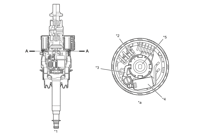
*1 Steering Actuator Assembly *2 Lock Holder *3 Lock Lever *4 Lock Solenoid *5 Motor Shaft - - *a A-A Cross Section - - -
When the lock mechanism is activated, the steering control ECU turns off the current to the lock solenoid, and the return spring pushes the lock lever against the lock holder. Then, the lock lever meshes with the groove in the lock holder in order to mechanically lock the movement of the motor. When the lock is disengaged, the steering control ECU turns ON the current to the lock solenoid, thus disengaging the lock lever and the lock holder and freeing the movement of the motor.
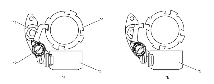
*1 Lock Lever *2 Return Spring *3 Lock Solenoid (Off State) *4 Lock Holder *5 Lock Solenoid (On State) - - *a Lock State *b Unlock State
-
-
Steering Torque Transmission
-
Low and Middle Speed Range
-
This system rotates the steering actuator in the positive direction in the low speed range (in which a reduction in the steering wheel operating effort is desired) or in the medium speed range (in which a more agile vehicle response is desired).
-
For example, if the driver turns the steering wheel clockwise, the torque is transmitted as illustrated below.
-
In order to create the target operating angle for the steering actuator that has been determined by the steering control ECU, the motor in the steering actuator rotates counter clockwise. Then, the rotational movement of the motor is input into the reduction mechanism by way of the wave generator. The rotational movement is reduced to a 1:50 gear ratio, and is output from the output shaft in the clockwise direction. This operating angle of the steering actuator is then added to the angle in which the steering wheel is steered by the driver. Thus, the output shaft rotates more clockwise than the steered angle of the steering wheel by the amount of the operating angle of the steering actuator. As a result, the front wheels turn more to the right.
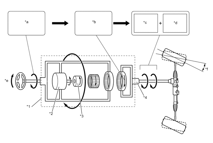
*1 Steering Actuator Assembly *2 Motor *3 Wave Generator *4 Output Shaft *a Steering Wheel Steered Angle *b Steering Actuator Operating Angle (Positive Direction) *c Steering Actuator Operating Angle *d Steering Wheel Steered Angle *e Right Turn *f Effectiveness of VGRS System -
High Speed Range
-
In the high speed range (in which an over-sensitive movement response of the vehicle is not desired), the steering actuator of this system rotates slightly in the negative direction.
-
For example, if the driver turns the steering wheel clockwise, the torque is transmitted as illustrated below.
-
In order to create the target operating angle for the steering actuator that has been determined by the steering control ECU, the motor in the steering actuator rotates clockwise. Then, the rotational movement of the motor is input into the reduction mechanism by way of the wave generator. The rotational movement is reduced to a 1:50 gear ratio, and is output a little from the output shaft in the counterclockwise direction. This operating angle of the steering actuator is then subtracted from the angle in which the steering wheel is steered by the driver. Thus, the output shaft rotates less clockwise than the steered angle of the steering wheel by the amount of the operating angle of the steering actuator. As a result, the front wheels turn less to the right.
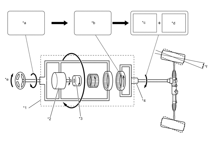
*1 Steering Actuator Assembly *2 Motor *3 Wave Generator *4 Output Shaft *a Steering Wheel Steered Angle *b Steering Actuator Operating Angle (Negative Direction) *c Steering Actuator Operating Angle *d Steering Wheel Steered Angle *e Right Turn *f Effectiveness of VGRS System Tech Tips
When the steering actuator rotates in the negative direction, it will not rotate in excess of the driver's steering angle.
-
-
-
-
System Operation
-
General
-
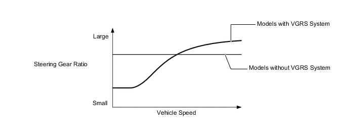
The steering control ECU calculates the steering actuator target operating angle based upon the steering angle sensor signal which is based on the steering wheel turning status and the vehicle speed signal which is transmitted from the skid control ECU. The steering control ECU operates the steering actuator until it reaches the target operating angle. The steering control ECU controls the turning angles of the front wheels by adding the operating angle of the steering actuator to the angle in which the steering wheel is steered by the driver. As a result, the steering gear ratio fluctuates depending on the driving conditions. Thus, excellent steering feel and vehicle stability is achieved, regardless of the vehicle speed, from the low to high-speed ranges.
-
The steering control ECU stores the neutral position of the steering actuator in its memory. Thus, the steering control ECU effects control by using this neutral position as a reference value. Furthermore, the steering control ECU constantly stores the operating angle of the steering actuator in its memory. These data that have been stored in memory will not be erased even if the battery terminals are disconnected.
-
-
Control with a signal from the skid control ECU
-
If a vehicle that driven straight ahead over a road surface with different friction coefficients brakes suddenly and causes the VSC to activate, the vehicle posture becomes disrupted, thus requiring the driver to operate the steering wheel. When this occurs, the skid control ECU transmits signals to the steering control ECU. When the steering control ECU receives these signals, it calculates the target operating angle for the steering actuator based on the driver's steering angle and direction (which are obtained from the steering angle sensor signals) and the vehicle speed signal (which is obtained from the skid control ECU). Then, the VGRS system operation, thus reducing the driver's steering ability.
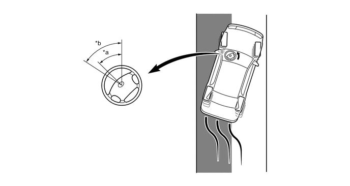
*a Driver's steering wheel angle by the control with a signal from the skid control ECU. *b Driver's steering wheel angle by the control without a signal from the skid control ECU. 
Slippery Surface - -
-
-
-
Fail-safe
-
If the steering control ECU detects a malfunction in the VGRS system, the ECU illuminates the master warning light, indicates the warning message on the multi-information display, sounds the buzzer to inform the driver, and stops the system control.
-
If a system malfunction occurs, it turns off the lock solenoid of the lock mechanism and locks the steering actuator motor.
-
-
Diagnosis
-
If a system malfunction occurs, Diagnostic Trouble Code (DTC) is stored in memory of the steering control ECU. The DTC can be read by connecting a Global TechStream (GTS) to the DLC3.
-
For details, refer to the Repair Manual.
Tech Tips
When the steering control ECU is replaced or when any parts between the steering wheel and tires are removed, replaced or adjusted, initialize the steering actuator neutral position stored in the steering control ECU memory. For details, refer to the Repair Manual.
-