BRAKE
-
General
-
The brake control system has the following functions:
Function Outline Multi-terrain Anti-lock Brake System (ABS) The ABS helps prevent the wheels from locking when the brakes are applied firmly or when braking on a slippery surface. In addition to the existing ABS function, the multi-terrain ABS automatically calculates the optimum ABS control in accordance with the off-road situation such as a dirt or sandy road. Electronic Brake force Distribution (EBD) The EBD utilizes multi-terrain ABS, realizing the proper brake force distribution between front and rear wheels in accordance with the driving conditions. In addition, during cornering braking, it also controls the brake forces of right and left wheels, helping to maintain the vehicle behavior. Brake Assist The primary purpose of the brake assist is to provide an auxiliary brake force to assist the driver who cannot generate a large brake force during emergency braking, thus helping draw the vehicle's brake performance. Tech Tips
When the brake control system is activated, the brake pedal could shudder, which is a normal occurrence of the system in operation and should not be considered a malfunction.
-
-
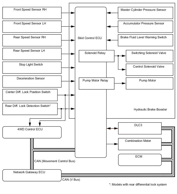
System Diagram
-
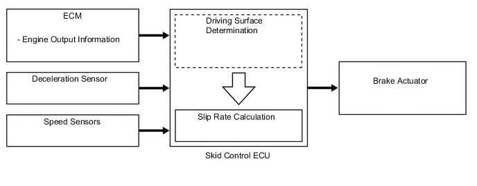
Outline of Multi-terrain ABS
-
General
-
The conventional ABS, by regulating the hydraulic brake pressure of all the wheels by monitoring the wheel speeds during braking, prevents the wheels from locking when braking to ensure the vehicle stability and the steering maneuverability. The multi-terrain ABS has a function that detects the off-road ground conditions such as sand, mud, or gravel via information such as the engine output, vehicle acceleration rate, and wheel speeds, and then selects the optimum ABS control in accordance with the situation. As a result, the braking feel in off-road driving has been enhanced.
-
-
Effective of Multi-terrain ABS
-
Through the addition of the engine output information to the existing control information, the accuracy of determining the road surface conditions has been more improved. By changing the slip rate in accordance with the road surface, the deceleration rate has been increased.
-
-
-
Outline of EBD
-
General
-
The distribution of the brake force, which was performed mechanically in the past, is now performed under electrical control of the skid control ECU, which precisely controls the braking force in accordance with the vehicle's driving conditions.
-
-
Front/ Rear Wheels Brake Force Distribution
-
If the brakes are applied while the vehicle is moving straight forward, the transfer of the road reduces the load that is applied to the rear wheels. The skid control ECU determines this condition by way of the signals from the speed sensor, and the master cylinder solenoid regulates the distribution of the brake force of the rear wheels to optimally control.
-
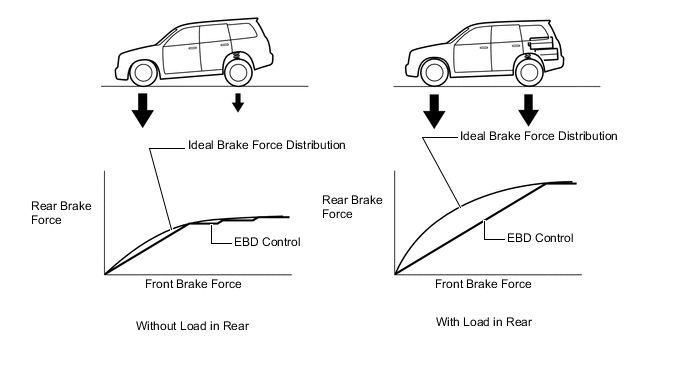
For example, the amount of the brake force that is applied to the rear wheels during braking varies whether or not the vehicle is carrying a load. The amount of the brake force that is applied to the rear wheels also varies in accordance with the extent of the deceleration.
-
Thus, the distribution of the brake force to the rear is optimally controlled in order to effectively utilize the braking force of the rear wheels under these conditions.
Figure 1. EBD Concept
-
-
Right/Left Wheels Brake Force Distribution (During Cornering Braking)
-
When the brakes are applied while the vehicle is cornering, the load that applied to the inner wheel decreases to the outer wheel increases.
-
The skid control ECU determines this condition by way of the signals from the speed sensor, and the master cylinder solenoid regulates the brake force in order to optimally control the distribution of the brake force to the inner wheel and outer wheel.

-
-
-
Outline of Brake Assist
-
The brake assist in combination with ABS helping improves the vehicle's brake performance.
-
The brake assist interprets a quick push of the brake pedal as emergency braking and supplements the brake power applied if the driver has not stepped hard enough on the brake pedal. In emergencies, driver, especially inexperienced ones, often panic and do not apply sufficient pressure on the brake pedal.
-
A key feature of brake assist is that the timing and the degree of braking assistance are designed to ensure that the driver does not discern anything unusual about the braking operation. When the driver intentionally eases up on the brake pedal, the system reduces the amount of assistance it provides.
-
Based on the signals from the master cylinder pressure sensor, the skid control ECU calculates the speed and the amount of the brake pedal application and then determines the intention of the driver to make an emergency braking. If the skid control ECU determines that the driver intends the emergency braking, the system activates the hydraulic brake booster to increase the brake fluid pressure, which increases the braking force.
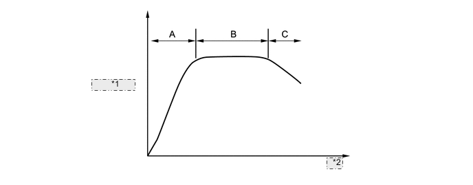
Figure 2. In case that the driver's depressing force is small when applying emergency braking
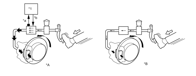
*A Models with Brake Assist *B Models without Brake Assist *1 Skid Control ECU - - *a Master Cylinder Pressure Sensor Signal *b The fluid pressure is increased by the hydraulic brake booster. 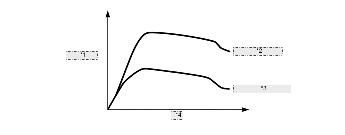
*1 Brake Force *2 With Brake Assist *3 Without Brake Assist *4 Time Tech Tips
There is no difference of the maximum brake performance between the vehicles with and without brake assist.
-
-
Layout of Main Components
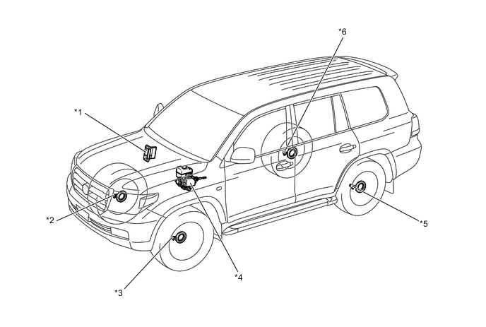
*1 ECM *2 Front Speed Sensor RH *3 Front Speed Sensors LH *4 Hydraulic Brake Booster *5 Rear Speed Sensor LH *6 Rear Speed Sensors RH 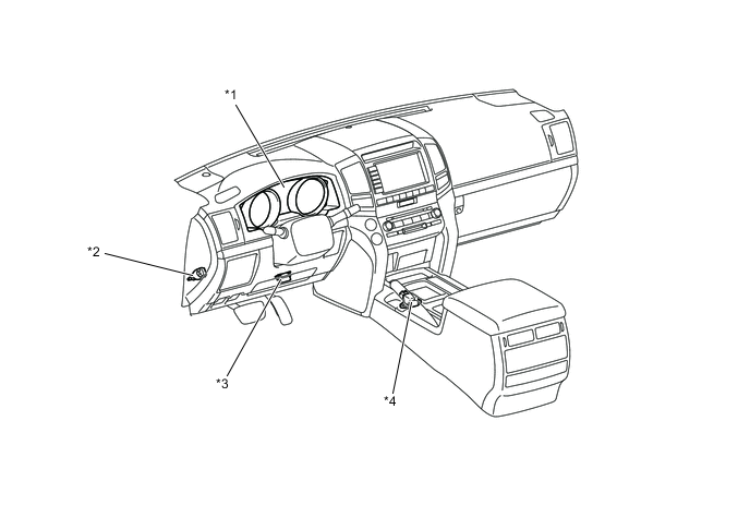
*1 Combination Meter *2 Stop Light Switch *3 DLC3 *4 Deceleration Sensor -
Function of Main Components
Components Function Hydraulic Brake Booster
-
Assists with the brake pedal effort applied to the brake pedal.
-
Changes the brake fluid path based on the signals from the skid control ECU during the operations of the multi-terrain ABS, EBD, brake assist in order to control the fluid pressure that is applied to the wheel cylinders.
Master Cylinder Pressure Sensor (Built into Hydraulic Brake Booster) Detects the master cylinder pressure. Accumulator Pressure Sensor (Built into Hydraulic Brake Booster) Monitors the hydraulic pressure of the accumulator and detects the hydraulic pressure for the pump motor operation. Brake Fluid Level Warning Switch (Built into Hydraulic Brake Booster) Detects the brake fluid level. Combination Meter Brake Warning Light
-
Lights up to alert the driver when a malfunction occurs in the EBD or skid control ECU.
-
Lights up to alert the driver that the hydraulic pressure of the accumulator in the hydraulic brake booster has decreased.
-
Lights up to alert the driver when the brake fluid in the reservoir tank reaches the low level.
ABS Warning Light Lights up to alert the driver when the skid control ECU detects a malfunction in the multi-terrain ABS, EBD or brake assist. Skid Control ECU Judges the vehicle driving condition based on signals from each sensor, and sends brake control signals to the master cylinder solenoid. Pump Motor Relay (Built into Skid Control ECU) Controls the pump motor operation in the hydraulic brake booster. Solenoid Relay (Built into Skid Control ECU) Supplies or cuts off power to solenoid valves in the master cylinder solenoid. Speed Sensor Detects the wheel speed and rotating direction of each of 4-wheel. Deceleration Sensor Detects the vehicle's acceleration in the forward, rearward, and lateral. Stop Light Switch Detects the brake pedal depressing signal. Center Diff. Lock Position Switch Detects the condition of the center differential lock. Rear Diff. Lock Detection Switch* Detects the condition of the rear differential lock. ECM Transmits the engine output information to the skid control ECU. *: Models with rear differential lock system
-
-
Construction of Main Components
-
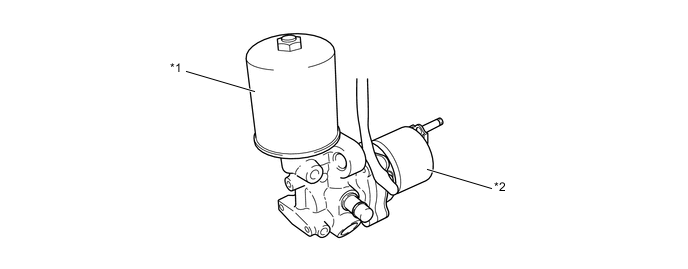
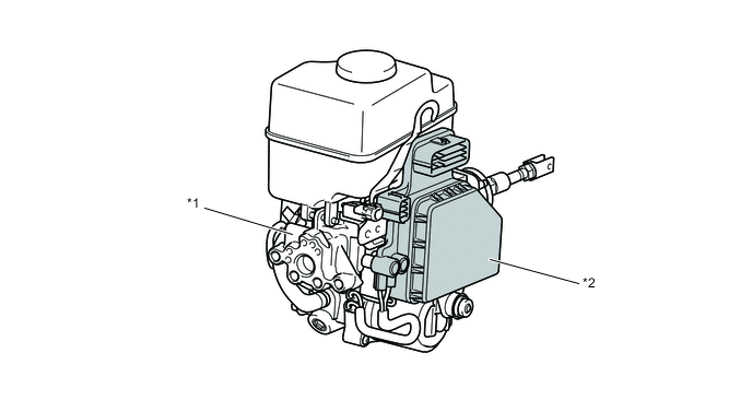
Hydraulic Brake Booster
-
The hydraulic brake booster assembly consists of the brake pressure generation portion, power supply portion, and brake control portion.
-
The brake pressure generation portion is a master cylinder and brake booster and master cylinder pressure sensor.
-
The power supply portion is a pump, pump motor, relief valve, reservoir tank, brake fluid level warning switch, accumulator and accumulator pressure sensor.
-
The brake control portion is a skid control ECU and master cylinder solenoid.
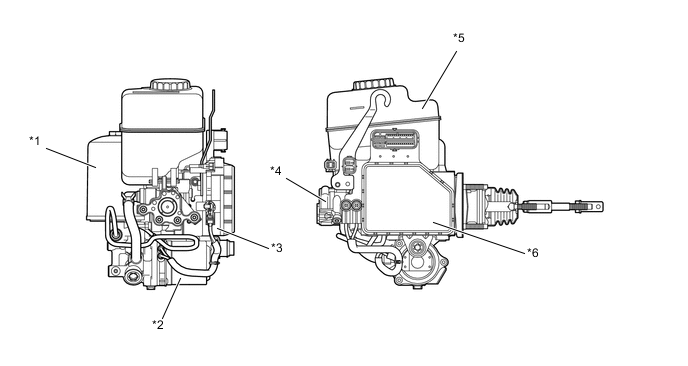
*1 Accumulator *2 Pump and Pump Motor *3 Master Cylinder Solenoid
-
Switching Solenoid Valves
-
Control Solenoid Valves
*4 Master Cylinder and Brake Booster *5 Brake Master Cylinder Reservoir Sub-assembly
-
Brake Fluid Level Warning Switch
*6 Skid Control ECU -
-
The hydraulic brake booster consists of the following components:
Components Function Brake Pressure Generation Portion Master Cylinder and Brake Booster
-
Generates the hydraulic pressure that is provided to the wheel cylinders during normal brake.
-
Regulates the accumulator pressure in accordance with the pedal effort that is applied to the brake pedal and introduce this pressure to the booster chamber in order to provide a power assist to the brakes.
Master Cylinder Pressure Sensor Detects the master cylinder pressure and outputs this signal to the skid control ECU. Power Supply Portion Pump and Pump Motor Draws up the brake fluid from the reservoir tank and provides high hydraulic pressure to the accumulator. Accumulator Stores the hydraulic pressure that was generated by the pump. The accumulator is filled with high-pressure nitrogen gas. Accumulator Pressure Sensor Monitors the hydraulic pressure of the accumulator and detects the hydraulic pressure for the pump motor operation. Relief Valve Returns the brake fluid to the reservoir tank to prevent excessive pressure if the pump operates continuously due to a malfunction of the pressure sensor. Brake Master Cylinder Reservoir Sub-assembly Stores the brake fluid. Brake Fluid Level Warning Switch Detects the low brake fluid level. Brake Control Portion Master Cylinder Solenoid Switching Solenoid Valve Switches the brake hydraulic path when the brake control system is activated. Control Solenoid Valve Controls the hydraulic pressure that is applied to the wheel cylinders during brake control. Skid Control ECU
-
Judges the vehicle driving condition based on signals from each sensor, and controls multi-terrain ABS, EBD and brake assist.
-
Operates the pump and pump motor to control accumulator pressure based on accumulator pressure sensor signal.
Figure 3. Hydraulic Circuit
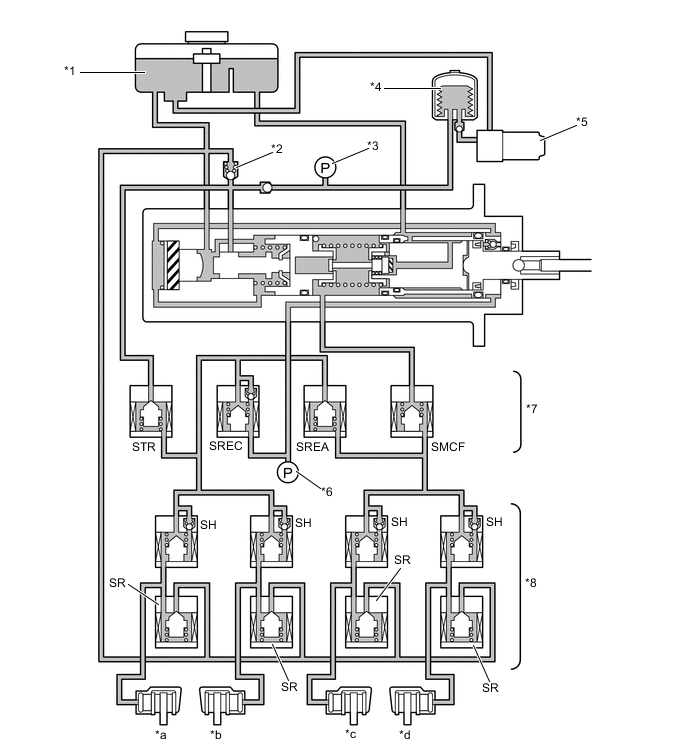
*1 Brake Master Cylinder Reservoir Sub-assembly *2 Relief Valve *3 Accumulator Pressure Sensor *4 Accumulator *5 Pump and Pump Motor *6 Master Cylinder Pressure Sensor *7 Switching Solenoid Valve *8 Control Solenoid Valve *a Rear LH *b Rear RH *c Front LH *d Front RH STR Traction Solenoid Valve (Accumulator Cut Solenoid Valve) SREC Regulator Cut Solenoid Valve SREA Regulator Apply for Front Solenoid Valve SMCF Master Cut for Front Solenoid Valve SH Pressure Holding Solenoid Valve SR Pressure Reduction Solenoid Valve -
-
-
Master Cylinder
-
Construction
-
The master cylinder consists of a brake booster portion, master cylinder portion and regulator portion. These are positioned coaxially to achieve a simple and compact construction.
-
The brake booster portion consists of an operation rod, power piston and booster chamber.
-
The master cylinder portion consists of a master cylinder piston (large diameter piston and small diameter piston), return spring and center valve.
-
The regulator portion consists of a regulator piston, return spring, spool valve, reaction rod and rubber reaction disc.
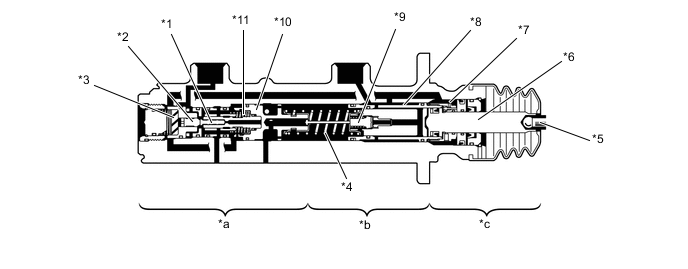
*1 Spool Valve *2 Reaction Rod *3 Rubber Reaction Disc *4 Return Spring *5 Operation Rod *6 Power Piston *7 Booster Chamber *8 Master Cylinder Piston *9 Center Valve *10 Regulator Piston *11 Return Spring - - *a Regulator Portion *b Master Cylinder Portion *c Brake Booster Portion - - 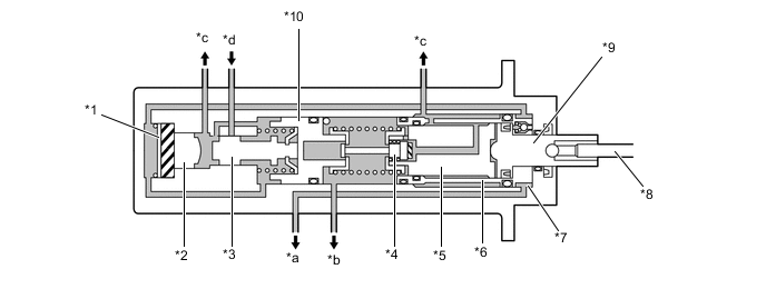
*1 Rubber Reaction Disc *2 Reaction Rod *3 Spool Valve *4 Center Valve *5 Master Cylinder Inner Piston (Small Diameter Piston) *6 Master Cylinder Outer Piston (Large Diameter Piston) *7 Booster Chamber *8 Operation Rod *9 Power Piston *10 Regulator Piston *a To Rear Brake *b To Front Brake *c To Reservoir Tank *d From Accumulator Tech Tips
The supply parts for the master cylinder and brake booster portion are provided as follows:
-
The operation rod and the power piston, which are integrated, are supplied as the No. 1 piston.
-
The master cylinder piston is supplied as the No. 2 piston.
-
Other parts are not available as supply parts, so do not remove them.
For detailed removal procedure, refer to the Repair Manual.
-
-
-
Operation
-
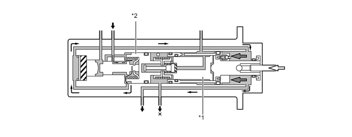
Pressure Increase (Low Pressure)
-
The pedal operation force transmits as follows: Operation Rod → Power Piston → Master Cylinder Piston (Small Diameter Piston).
-
The load setting of the master cylinder's return spring is higher than that of the regulator piston's return spring, the regulator piston gets pushed before the volume in the master cylinder becomes compressed.
-
The spool valve closes the port "A" (between the reservoir tank and booster chamber) and opens the port "B" (between the reservoir tank and accumulator). Then, the pressurized brake fluid is introduced into the booster chamber to provide a power assist to the pedal effort. The pressure of the pressurized brake fluid is transmitted to the large diameter master cylinder piston.
-
This time, the power assist overcomes the force of the master cylinder's return spring. This causes the volume in the master cylinder to become compressed and increased the pressure that is applied to the front brakes. At the same, the pressure in the booster chamber increases the pressure that is applied to the rear brakes.
*1 Rubber Reaction Disc *2 Reaction Rod *3 Spool Valve *4 Master Cylinder Outer Piston (Large Diameter Piston) *5 Operation Rod *6 Master Cylinder Inner Piston (Small Diameter Piston) *7 Port B *8 Port A *a From Accumulator *b To Rear Brake *c To Front Brake - - -
During the initial stage of the brake operation, the booster pressure that is applied to the rubber reaction disc is small. Therefore, a return force in the rightward direction does not apply to the spool valve via the reaction rod.
-
Pressure Increase (High Pressure)
-
In contrast to the time when the pressure is low, when the pressure is high, the booster pressure that is applied to the rubber reaction disc increases. Accordingly, the rubber reaction disc deforms and causes a return force in the rightward direction to be applied to the spool valve via the reaction rod. Therefore, in contrast to the time when the pressure is low, a greater reaction force is transmitted to the brake pedal.
-
As a result, a variable servo mechanism is realized, in which the servo ratio is lower during high pressure than during low pressure.
*1 Rubber Reaction Disc *2 Reaction Rod *3 Spool Valve - - *a Booster Pressure - - -
Holding
-
This is a state in which the force that is applied via the brake pedal and the master cylinder pressure are in balance.
-
The forces that are applied to the front and the rear of the regulator piston, in other words, the forces that are generated by the master cylinder pressure and the regulator pressure become balanced. This causes the spool valve to close both the port B (between the reservoir tank and the accumulator) and the port A (between the booster chamber and reservoir tank). As a result, the brake is in the holding state.
*1 Rubber Reaction Disc *2 Port A *3 Port B *4 Regulator Valve *5 Spool Valve *6 Reaction Rod -
Pressure Reduce
-
When the pressure that is applied to the brake pedal is released, the master cylinder pressure decreases. Then, the regulator piston's return (rightward) force becomes relatively greater, causing the regulator piston and the spool valve to retract. As a result, the port A between the reservoir tank and the booster chamber opens.
-
The booster pressure becomes reduced in this state, creating a balance that corresponds to the change of brake pedal application force. This process occurs constantly to reduce the booster pressure and the master cylinder pressure in accordance with the force that is applied via the brake pedal.
*1 Rubber Reaction Disc *2 Reaction Rod *3 Spool Valve *4 Regulator Valve *5 Port A - - *a To Reservoir Tank - - -
During Power Supply Malfunction
-
If the accumulator pressure is affected by any malfunction, no hydraulic pressure will be supplied to the booster chamber. For this reason, a power assist cannot be provided to the force that is applied via the brake pedal and the pressure to the rear brakes cannot be increased. Since there is no pressurized brake fluid in the large diameter master cylinder piston at this time, the piston does not move from the original position.
-
However, the pressure to the front brakes will be increased at the small diameter master cylinder piston in accordance with the pedal effort applied to the brake pedal.
*1 Master Cylinder Inner Piston (Small Diameter Piston) *2 Master Cylinder Outer Piston (Large Diameter Piston) *a Accumulator Pressure - - -
Front Brake System Malfunction
-
In the front brake system, the master cylinder piston is moved by the booster chamber pressure but the hydraulic pressure does not increase. The piston moves until it hits the regulator piston while the brake fluid in the master cylinder is drained.
-
The rear brake system operates the same as in the normal operation.
*1 Master Cylinder Piston *2 Regulator Valve
-
-
-
Pump and Accumulator
-
General
-
A plunger type pump is used. This pump is driven by the pump motor, and generates high hydraulic pressure, and then supplies the hydraulic pressure to the accumulator.
-
Inside the accumulator, the high-pressurized nitrogen gas is charged and sealed. In addition, metallic bellows-formed tube is used, in order to enhance the gastight performance of the accumulator.
*1 Accumulator *2 Pump Motor Figure 4. Simplified Diagram
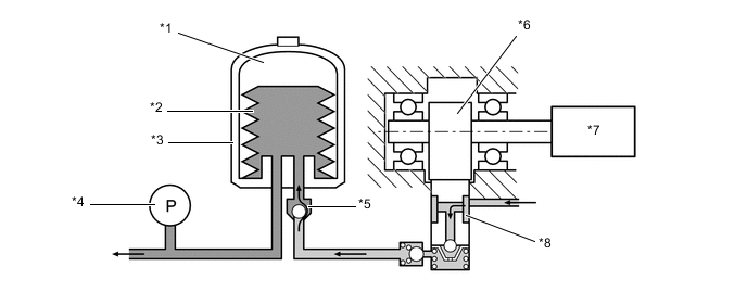
*1 Nitrogen Gas *2 Bellows-formed Tube *3 Accumulator *4 Accumulator Pressure Sensor *5 Check Valve *6 Camshaft *7 Pump Motor *8 Pump
-
-
Operation
-
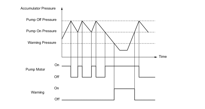
The power supply portion operates based on the accumulator pressure sensor signal as shown in the timing chart below.
-
When the accumulator pressure drops to "pump on pressure", the skid control ECU operates the pump motor.
-
When the accumulator pressure increases to "pump off pressure", the skid control ECU stops the pump motor.
-
When the accumulator pressure drops below the "warning pressure" level, the skid control ECU illuminates all warning and indicator lights other than the downhill assist control and CRAWL indicator lights, displays messages on the multi-information display, and sounds the skid control buzzer continuously.
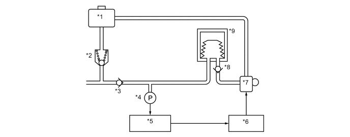
*1 Reservoir Tank *2 Relief Valve *3 Check Valve *4 Accumulator Pressure Sensor *5 Skid Control ECU *6 Motor Relays *7 Pump Motor *8 Check Valve *9 Accumulator - - Figure 5. Timing Chart
-
-
-
Master Cylinder Solenoid
-
General
-
The master cylinder solenoid consists of switching solenoid valves and control solenoid valves.
*1 Master Cylinder Solenoid *2 Skid Control ECU Figure 6. Hydraulic Circuit
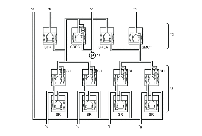
*1 Master Cylinder Pressure Sensor *2 Switching Solenoid Valve *3 Control Solenoid Valve - - *a To Reservoir Tank *b From Accumulator *c From Master Cylinder and Brake Booster *d Rear LH *e Rear RH *f Front LH *g Front RH - -
-
-
Solenoid Valve
-
There are 2 types of solenoid valves: the switching solenoid valve and the control solenoid valve.
-
A total of 4 switching solenoid valves are used: 2 (SMCF, SREA) in the front brake fluid path, 1 (SREC) in the rear brake fluid path, and 1 (STR) in the accumulator fluid path. The switching valves open and close in accordance with the control signals from the skid control ECU in order to switch the respective brake fluid paths.
-
A total of 8 control solenoid valves are used for the 4 wheels (2 types per wheel: pressure holding solenoid and pressure reduction solenoid).
-
The pressure increase mode, the pressure holding mode, and the pressure reduction mode are effected based on the combination of these valves that are turned on and off, in order to control the hydraulic pressure that is applied to each of the wheel cylinders.
-
-
-
Speed Sensor
-
General
-
Active type speed sensors, which can detect the rotational direction of the wheel, have been provided. This sensor contains a sensor IC, which consists of 2 Magnetic Resistance Elements (MREs).
-
The sensor rotor, which consists of N and S poles that are arranged in a circle, is integrated with the inner race of the hub bearing.
-
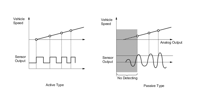
The difference between the passive type speed sensor (containing a pick-up coil to detect speeds) and the active type speed sensors are described below.
Figure 7. Active Type Speed Sensor
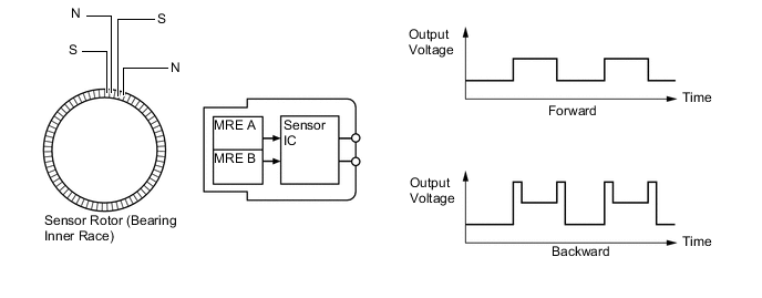
Figure 8. Passive Type Speed Sensor
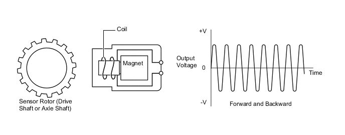
Sensor Type Active Passive Direction Detection Possible to judge both forward and backward Impossible to judge the wheel rotation direction Detection Speed Approx. 0 km/h (0 mph) 3 km/h (5 mph) more than Weight Approx. 1/3 of passive type -
-
-
Detection Method
-
To detect the rotation direction, the output waves are used to determine the relationship of the pulses that are generated by the 2 MREs.
-
Upon receiving this signal, the sensor IC outputs a forward or backward wave.
Figure 9. Forward
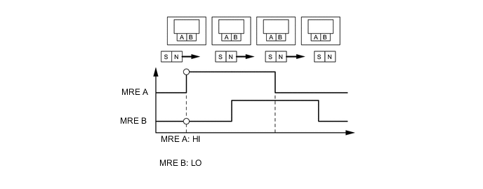
Figure 10. Backward
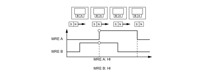
-
To detect the vehicle speed, the duration of the output pulses is used. Because the active type sensor outputs digital pulses, it can detect vehicle speeds even at approximately 0 km/h (0 mph).
-
-
-
-
System Operation
-
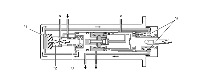
Normal Braking
-
During normal braking, all solenoid valves are turned off.
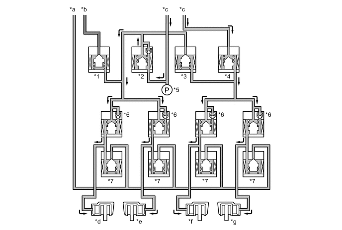
*1 Traction Solenoid Valve (Accumulator Cut Solenoid Valve) (STR) *2 Regulator Cut Solenoid Valve (SREC) *3 Regulator Apply for Front Solenoid Valve (SREA) *4 Master Cut for Front Solenoid Valve (SMCF) *5 Master Cylinder Pressure Sensor *6 Pressure Holding Solenoid Valve (SH) *7 Pressure Reduction Solenoid Valve (SR) - - *a To Master Cylinder Reservoir Sub-assembly *b From Brake Booster Accumulator Assembly *c From Master Cylinder *d Rear LH *e Rear RH *f Front LH *g Front RH - -
-
-
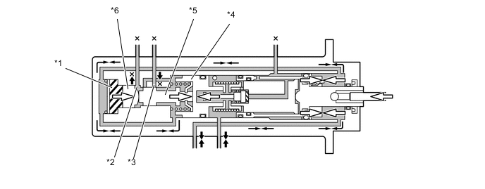
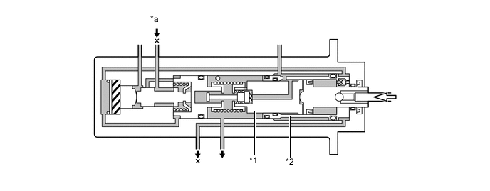
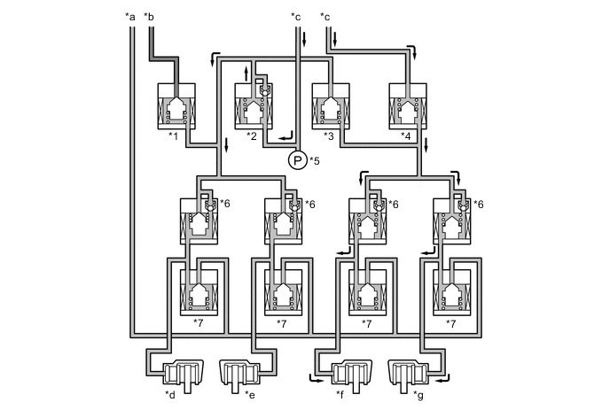
Multi-terrain ABS and EBD Operation
-
The skid control ECU calculates the wheel speeds and deceleration rates, and checks the wheel slipping condition based on signals from the 4 wheel speed sensors and the deceleration sensor as well as the engine output information transmitted from the ECM.
-
The ECU compares the speed sensor signals of the front and rear, judges the slipping condition of the rear wheel, and operates the EBD.
-
If the wheel is likely to be locked, the ECU controls the pressure holding solenoid valve and pressure reduction solenoid valve as multi-terrain ABS operation in the following 3 modes: increase, hold and reduce.
Figure 11. EBD Operation
*1 Traction Solenoid Valve (Accumulator Cut Solenoid Valve) (STR) *2 Regulator Cut Solenoid Valve (SREC) *3 Regulator Apply for Front Solenoid Valve (SREA) *4 Master Cut for Front Solenoid Valve (SMCF) *5 Master Cylinder Pressure Sensor *6 Pressure Holding Solenoid Valve (SH) *7 Pressure Reduction Solenoid Valve (SR) - - *a To Master Cylinder Reservoir Sub-assembly *b From Brake Booster Accumulator Assembly *c From Master Cylinder *d Rear LH *e Rear RH *f Front LH *g Front RH - - Figure 12. Multi-terrain ABS Operation
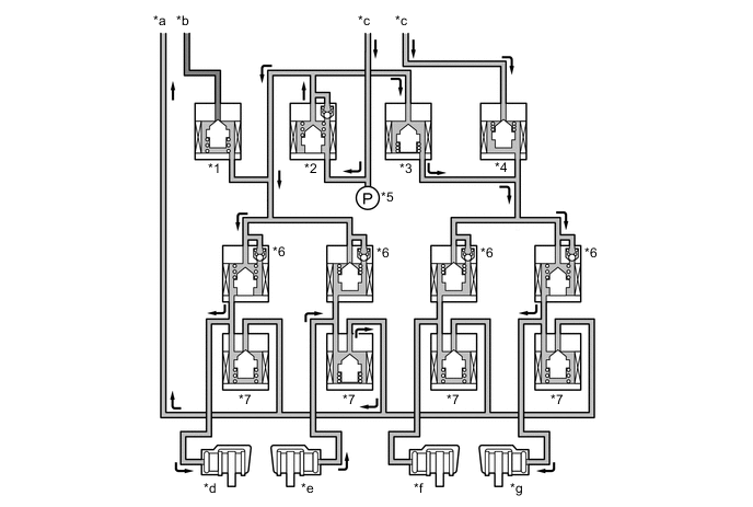
*1 Traction Solenoid Valve (Accumulator Cut Solenoid Valve) (STR) *2 Regulator Cut Solenoid Valve (SREC) *3 Regulator Apply for Front Solenoid Valve (SREA) *4 Master Cut for Front Solenoid Valve (SMCF) *5 Master Cylinder Pressure Sensor *6 Pressure Holding Solenoid Valve (SH) *7 Pressure Reduction Solenoid Valve (SR) - - *a To Master Cylinder Reservoir Sub-assembly *b From Brake Booster Accumulator Assembly *c From Master Cylinder *d Rear LH *e Rear RH *f Front LH *g Front RH - - Item Not Activated Multi-terrain ABS and EBD Activated Increase Mode Holding Mode Reduction Mode SREC Off (Open) ← ← ← STR Off (Closed) ← ← ← Front Brake SMCF*1 Off (Open) On (Closed) ← ← SREA*1 Off (Closed) On (Open) ← ← SH Off (Open) ← On (Closed) ← SR Off (Closed) ← ← On (Open) Wheel Cylinder Pressure - Increase Hold Reduce Rear Brake SH*2 Off (Open) ← On (Closed) ← SR Off (Closed) ← ← On (Open) Wheel Cylinder Pressure - Increase Hold Reduce Tech Tips
*1: While the front wheels are in multi-terrain ABS operation, SMCF and SREA are on. While only rear wheels are in multi-terrain ABS operation, SMCF and SREA are off.
*2: During EBD operation, only SH for both rear wheels is on (close).
-
-
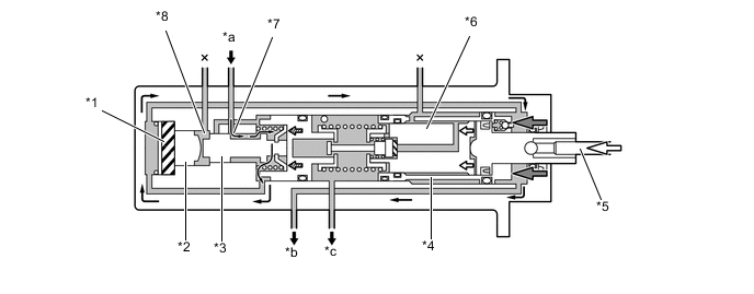
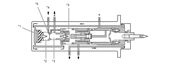
Brake Assist Operation
-
If an emergency braking situation has occurred, it is detected by the skid control ECU based on the vehicle speed signal from the speed sensor, the brake pedal application speed from the master cylinder pressure sensor, and the signal representing the amount of pedal effort. Then, the skid control ECU actuates each solenoid valve. As a result, the pressure from the accumulator is applied to the wheel cylinders. The accumulator pressure that is applied to the wheel cylinders generates a higher pressure than the master cylinder.
Figure 13. Brake Assist Operation
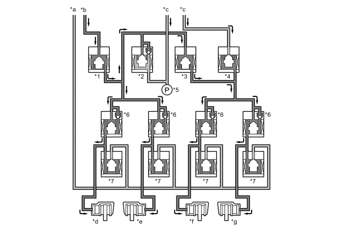
*1 Traction Solenoid Valve (Accumulator Cut Solenoid Valve) (STR) *2 Regulator Cut Solenoid Valve (SREC) *3 Regulator Apply for Front Solenoid Valve (SREA) *4 Master Cut for Front Solenoid Valve (SMCF) *5 Master Cylinder Pressure Sensor *6 Pressure Holding Solenoid Valve (SH) *7 Pressure Reduction Solenoid Valve (SR) - - *a To Master Cylinder Reservoir Sub-assembly *b From Brake Booster Accumulator Assembly *c From Master Cylinder *d Rear LH *e Rear RH *f Front LH *g Front RH - - Figure 14. Brake Assist Timing
*1 Brake Force *2 Time Item Not Activated Multi-terrain ABS and EBD Activated Increase Mode Holding Mode Reduction Mode SREC Off (Open) On (Closed) ← On (Open) STR Off (Closed) On (Open) ← Off (Closed) Front Brake SMCF Off (Open) On (Closed) ← ← SREA Off (Closed) On (Open) ← ← SH Off (Open) ← On (Closed) ← SR Off (Closed) ← ← On (Open) Rear Brake SH Off (Open) ← On (Closed) ← SR Off (Closed) ← ← On (Open) Wheel Cylinder Pressure - Increase Hold Reduce
-
-
Initial Check
-
Each time the engine switch is turned IG-ON, and the vehicle reaches approximately speed of 6 km/h (4 mph) or more, the skid control ECU performs the initial check.
-
The functions of each solenoid valve in the hydraulic brake booster are checked in order.
-
-
-
Diagnosis
-
If the skid control ECU detects a malfunction in the brake control system, the warning lights or indicator light illuminate. At the same time, a Diagnostic Trouble Code (DTC) is stored in the memory of the skid control ECU.
-
This system has a sensor signal check (test mode) function.
-
For details of DTCs and check function, refer to the Repair Manual.
-
-
Fail-safe
-
If a failure occurs in the skid control ECU, sensors or brake actuator assembly, the system continues effecting brake control by excluding the failed area and using only the areas that are operating normally.
-