SUSPENSION AND AXLE
-
General
-
The Kinetic Dynamic Suspension System (KDSS) consists of a hollow stabilizer bar at the front and a sold stabilizer bar at the rear to realize the proper rolling rigidity of the vehicle, and two hydraulic stabilizer control cylinders to deliver excellent off-road driving performance.
-
The 2 stabilizer control cylinders are piped via the valve unit.
Tech Tips
-
This system uses the suspension fluid AHC.
-
Before removing a stabilizer control cylinder, which contains high pressure, make sure to drain the fluid from the bleeder plugs for the upper and lower chambers.
-
After installing a stabilizer control cylinder, make sure to use the SST to bleed air from the system.
-
For details, refer to the Repair Manual.
-
-
-
System Diagram
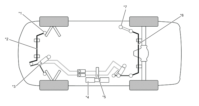
*1 Front Stabilizer Bar Link Assembly *2 Front Stabilizer Bar *3 Front Stabilizer Control Cylinder *4 Stabilizer Control Accumulators *5 Valve Unit
-
Accumulator valve
-
Relief valve
*6 Rear Stabilizer Bar Assembly *7 Stabilizer Link Sub-assembly - - -
-
Layout of Main Components
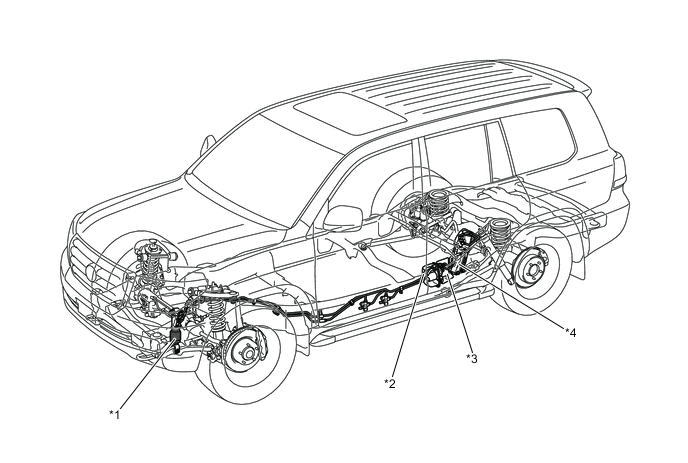
*1 Front Stabilizer Control Cylinder *2 Valve Unit
-
Accumulator Valve
-
Relief Valve
*3 Stabilizer Control Accumulators *4 Rear Stabilizer Control Cylinder -
-
Construction
-
Stabilizer Control Cylinder
-
Stabilizer control cylinder consists of the piston and upper and lower chambers. There is no connection between the upper and lower chambers. The front upper chamber is connected to the rear upper chamber, and the front lower chamber is connected to the rear lower chamber.
-
A bleeder plug is provided for each chamber. To remove a stabilizer control cylinder, fluid must be drained from the bleeder plug.
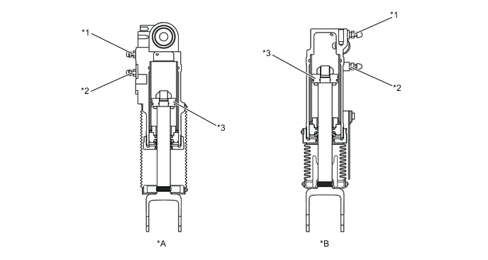
*A Front *B Rear *1 Bleeder Plug for Upper Chamber *2 Bleeder Plug for Lower Chamber *3 Piston - -
-
-
Stabilizer Control Accumulator
-
Inside the stabilizer control accumulator, the high-pressurized nitrogen gas is charged and sealed. In addition, metallic bellows-formed tube is used, in order to enhance the gastight performance of the stabilizer control accumulator.
-
The nitrogen gas filled with the stabilizer control accumulator produces the initial pressure inside the system piping and absorbs the pressure from the stabilizer control cylinder, and the fluid volume also varies in accordance with the temperature, thus contributing to an increase in the riding comfort.
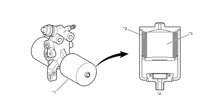
*1 Accumulator *2 Bellows-formed *3 Nitrogen Gas - - *a Cross Section - - Tech Tips
To prevent hazardous conditions, make sure to empty the gas from the accumulator before discarding a high-pressure (N2) gas sealed stabilizer control accumulator. For details, refer to the Repair Manual.
-
-
Valve Unit
-
The valve unit consists of an accumulator valve and a relief valve.
-
The accumulator valve is normally open, and opens and closes the fluid channel from the upper and lower chambers of the stabilizer control cylinder to the accumulator using the check ball.
-
If the fluid pressure inside the upper chamber or lower camber rises above a specified value, the relief valve opens to let the fluid flow into the accumulator, preventing the system from being damaged.
Figure 1. Simplified Diagram of Valve Unit
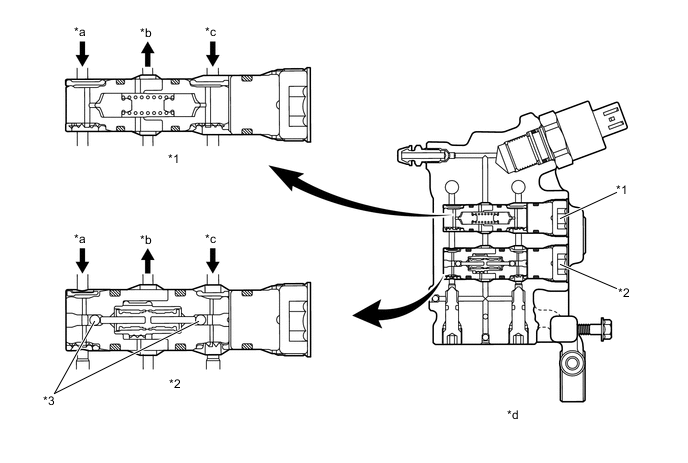
*1 Relief Valve *2 Accumulator Valve *3 Check Balls - - *a From Upper Chamber *b To Accumulator *c From Lower Chamber *d Valve Unit Cross Section
-
-
-
Operation
-
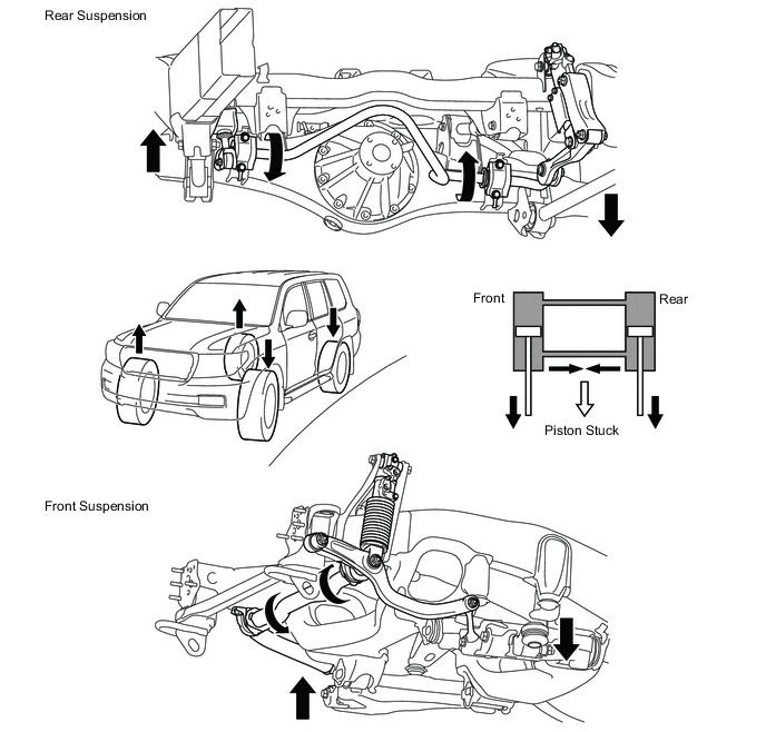
In a Roll Motion
-
During a rolling motion, no stroking movement occurs in the stabilizer control cylinders. Instead, the stabilizer bars operate effectively. As a result, a high level of driving stability is ensured.
-
-
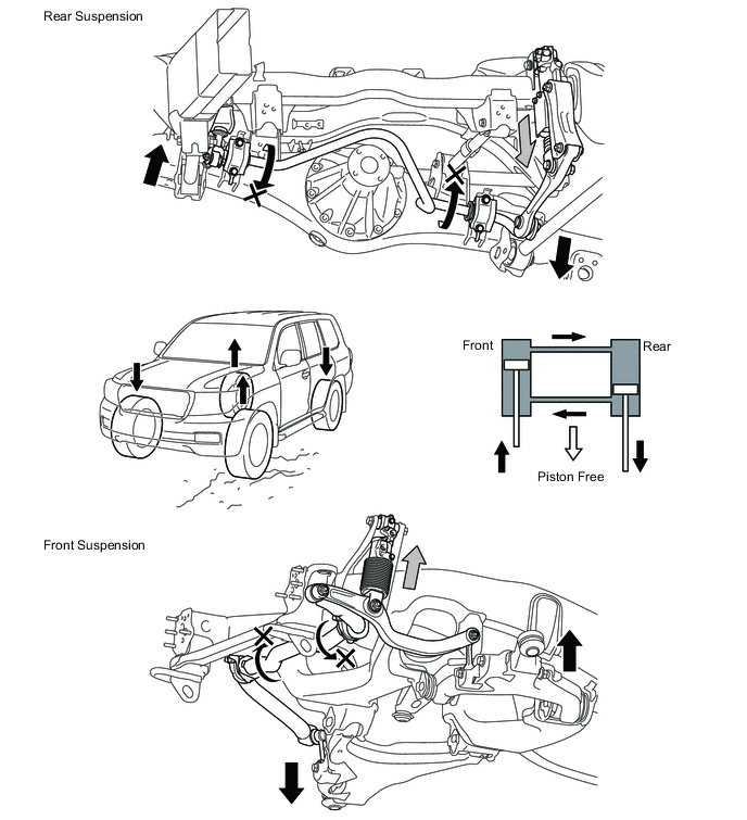
In Off-road Motion
-
During an off-road motion, a stroking movement occurs in the stabilizer control cylinders, and the effectiveness of the stabilizer bars is reduced. Thus, the suspension moves easily, free of torsion. As a result, an excellent performance is realized on the off-road driving.
-
-