AB60F AUTOMATIC TRANSMISSION
-
GENERAL
-
A gate type shift lever is used.
-
Shift pattern is provided with the S mode position on the side of the D position.
-
A shift lock system is used.
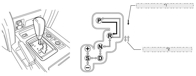
*1 The shift lever can be moved only with the engine switch IG-ON and the brake pedal depressed. *2 The shift lever can be moved at anytime.
-
-
SHIFT LOCK SYSTEM
-
General
-
The shift lock mechanism prevents the shift lever from being shifted to any position other than the P position, unless the IG-ON mode is selected, and the brake pedal is depressed. This mechanism helps to prevent unintentional acceleration.
-
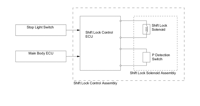
The shift lock system mainly consists of the shift lock control ECU, shift lock solenoid P detection switch and shift lock override button.
Figure 1. System Diagram
-
-
-
LAYOUT OF MAIN COMPONENTS
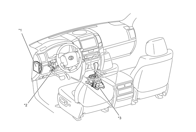
*1 Main Body ECU *2 Stop Light Switch *3 Shift Lock Control ECU
-
P Detection Switch
-
Shift Lock Solenoid
- - -
-
SYSTEM OPERATION
-
The shift lock ECU uses the P detection switch to detect the shift lever position, and receives inputs from the stop light switch and the main body ECU. Upon receiving these signals, the shift lock ECU turns ON the shift lock solenoid in order to release the shift lock.
-
A shift lock override button, which manually overrides the shift lock mechanism, is used.
-