AB60F AUTOMATIC TRANSMISSION
-
CONSTRUCTION
-
The planetary gear unit consists of three planetary gear units, four clutches, four brakes, and four one-way clutches.
-
A centrifugal fluid pressure canceling mechanism is used in the C1, C2, C3, and C4 clutches that are applied when shifting 2nd → 3rd, 3rd → 4th, 4th → 5th, and 5th → 6th.
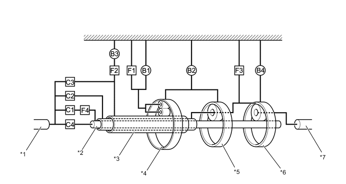
*1 Input Shaft *2 Intermediate Shaft *3 Sun Gear *4 Front Planetary Gear *5 Center Planetary Gear *6 Rear Planetary Gear *7 Output Shaft - -
-
-
-
FUNCTION OF COMPONENTS
Component Function C1 No. 1 Clutch Connects the input shaft, F4 and intermediate shaft. C2 No. 2 Clutch Connects the input shaft and center planetary carrier. C3 No. 3 Clutch Connects the input shaft and sun gear. C4 No. 4 Clutch Connects the input shaft and intermediate shaft. B1 No. 1 Brake Prevents the front planetary carrier from turning either clockwise or counterclockwise. B2 No. 2 Brake Prevents the front and the center ring gears from turning either clockwise or counterclockwise. B3 No. 3 Brake Prevents outer race of F2 from turning either clockwise or counterclockwise. B4 No. 4 Brake Prevents center planetary carrier and the rear ring gear from turning either clockwise or counterclockwise. F1 1-Way Clutch Prevents the front planetary carrier from turning counterclockwise. F2 No. 2 1-Way Clutch When B3 is operating, the one-way clutch prevents the front sun gear from turning counterclockwise. F3 No. 3 1-Way Clutch Prevents the center planetary carrier and the rear ring gear from turning counterclockwise. F4 No. 4 1-Way Clutch Prevents the intermediate shaft from turning counterclockwise. Planetary Gears These gears change the route through which driving force is transmitted, in accordance with the operation of each clutch and brake, in order to increase or reduce the output shaft speed. -
TRANSMISSION POWER FLOW
Shift Lever Position Solenoid Valve S1 S2 S3 S4 P - On On - R* - On On - N - On On - D, S6 1st - On On - 2nd On On On - 3rd On - On - 4th* On - - - 5th* On - - On 6th* On On - On S5 1st - On On - 2nd On On On - 3rd On - On - 4th* On - - - 5th* On - - On S4 1st - On On - 2nd On On On - 3rd On - On - 4th* On - - - S3 1st - On On - 2nd On On On - 3rd* On - On - S2 1st - On On - 2nd* On On On On S1 1st* - On On - *: with engine brake
Shift Lever Position Solenoid Valve SR SL1 SL2 SLU P On - On - R* On - On - N On - On - D, S6 1st On - On - 2nd On - On On 3rd On - On On 4th* On - On On 5th* - On - On 6th* - On - On S5 1st On - On - 2nd On - On On 3rd On - On On 4th* On - On On 5th* - On - On S4 1st On - On - 2nd On - On On 3rd On - On On 4th* On - On On S3 1st On - On - 2nd On - On On 3rd* On - - On S2 1st On - On - 2nd* On - - On S1 1st* On - - - *: with engine brake
Shift Lever Position Clutch C1 C2 C3 C4 P - - - - R* - - ○ - N - - - - D, S6 1st ○ - - ○ 2nd ○ - - ○ 3rd ○ - ○ ○ 4th* ○ ○ ● ○ 5th* ● ○ ○ - 6th* ● ○ - - S5 1st ○ - - ○ 2nd ○ - - ○ 3rd ○ - ○ ○ 4th* ○ ○ ● ○ 5th* ● ○ ○ - S4 1st ○ - - ○ 2nd ○ - - ○ 3rd ○ - ○ ○ 4th* ○ ○ ● ○ S3 1st ○ - - ○ 2nd ○ - - ○ 3rd* ○ - ○ ○ S2 1st ○ - - ○ 2nd* ○ - - ○ S1 1st* ○ - - ○ ○: Operates
●: Operates but is not related to power transmission
*: with engine brake
Shift Lever Position Brake B1 B2 B3 B4 P - - - - R* ○ - - ○ N - - - - D, S6 1st - - - - 2nd - - ○ - 3rd - - ● - 4th* - - ● - 5th* ○ - ● - 6th* ● ○ ● - S5 1st - - - - 2nd - - ○ - 3rd - - ● - 4th* - - ● - 5th* ○ - ● - S4 1st - - - - 2nd - - ○ - 3rd - - ● - 4th* - - ● - S3 1st - - - - 2nd - - ○ - 3rd* ▲ - ● - S2 1st - - - - 2nd* - ▲ ○ - S1 1st* - - - ▲ ○: Operates
●: Operates but is not related to power transmission
▲: Operates during engine braking
*: with engine brake
Shift Lever Position One-way Clutch F1 F2 F3 F4 P - - - - R* ○ - - - N - - - - D, S6 1st - - ○ ○ 2nd ○ ○ - ○ 3rd ○ - - ○ 4th* - - - ○ 5th* - - - - 6th* - - - - S5 1st - - ○ ○ 2nd ○ ○ - ○ 3rd ○ - - ○ 4th* - - - ○ 5th* - - - - S4 1st - - ○ ○ 2nd ○ ○ - ○ 3rd ○ - - ○ 4th* - - - ○ S3 1st - - ○ ○ 2nd ○ ○ - ○ 3rd* ○ - - ○ S2 1st - - ○ ○ 2nd* ○ ○ - ○ S1 1st* - - ○ ○ ○: Operates
*: with engine brake
-
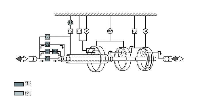
1st Gear (D Position or S Mode)
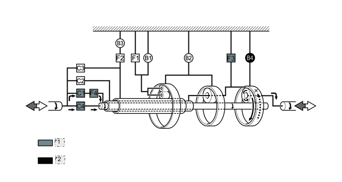
*1 Operates *2 Operates only in the S1 range -
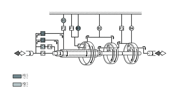
2nd Gear (D Position or S Mode)
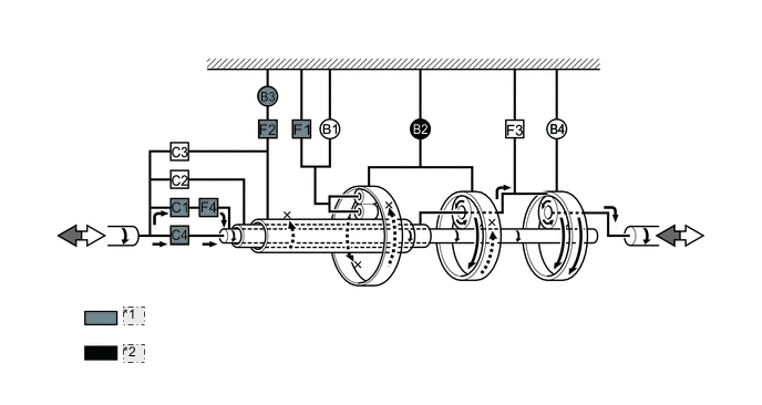
*1 Operates *2 Operates only in the S2 range -
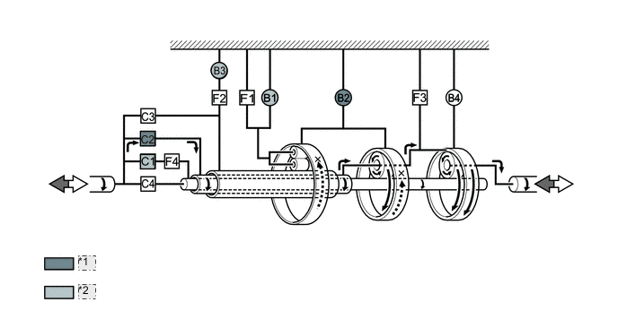
3rd Gear (D Position or S Mode)
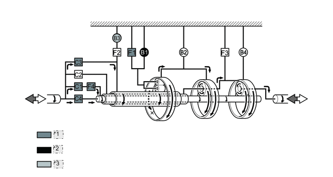
*1 Operates *2 Operates only in the S3 range *3 Operates but is not related to power transmission -
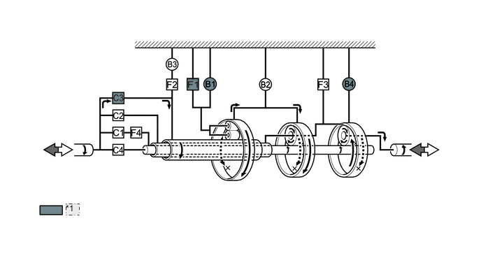
4th Gear (D Position or S Mode)
*1 Operates *2 Operates but is not related to power transmission -
5th Gear (D Position or S Mode)
*1 Operates *2 Operates but is not related to power transmission. -
6th Gear (D Position or S Mode)
*1 Operates *2 Operates but is not related to power transmission -
Reverse Gear (R Position)
*1 Operates
-
-
CENTRIFUGAL FLUID PRESSURE CANCELING MECHANISM
-
For the following reason, the centrifugal fluid pressure canceling mechanism is used on the C1, C2, C3, and C4 clutches.
-
Clutch shifting operation is affected not only by the valve body controlling fluid pressure but also by centrifugal fluid pressure that is present due to fluid in the clutch piston oil pressure chamber. The centrifugal fluid pressure canceling mechanism has chamber B to reduce this affect applied to the chamber A. As a result, smooth shifting with excellent response has been achieved.
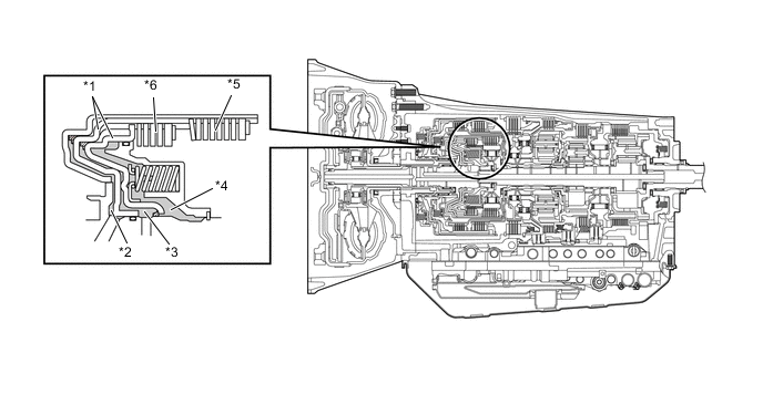
*1 Piston *2 Chamber A (for C1) *3 Chamber A (for C4) *4 Chamber B *5 C1 Clutch *6 C4 Clutch 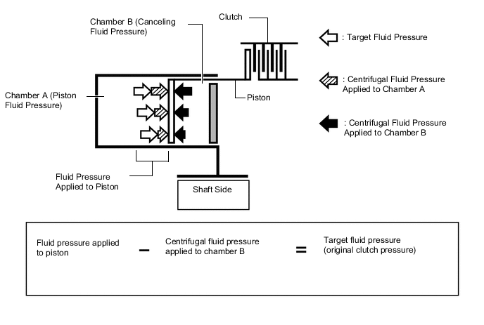
-
-