MULTIPLEX COMMUNICATION
-
GENERAL
-
The Controller Area Network (CAN) is a serial data communication network for real time application. It is a multiplex communication network equipped in a vehicle, and has communication speeds of 500 kbps (HS-CAN) and 250 kbps (MS-CAN), and the ability to detect malfunctions.
-
The HS-CAN consists of the V Bus and Movement Control Bus.*
*: Models with movement control Bus
-
The MS-CAN consists of the MS Bus.
-
The network gateway ECU has a gateway function and is used to transmit data between the V bus and Movement Control Bus*.
*: Models with network gateway ECU
-
The main body ECU has a gateway function and is used to transmit data between the V Bus and MS Bus.
-
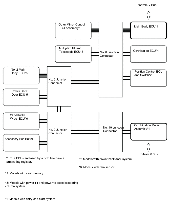
The CAN has 2 terminating resistors which are necessary for accurate judgment of communication on the main bus.
-
The communication wire used is a twisted-pair wire. The bus line has a high line (2.5 V to 3.5 V of voltage is applied) and a low line (1.5 V to 2.5 V of voltage is applied).
-
-
SYSTEM DIAGRAM
-
Models with Network Gateway ECU
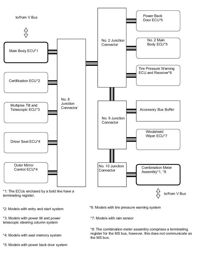
Figure 1. V Bus (LHD Models)
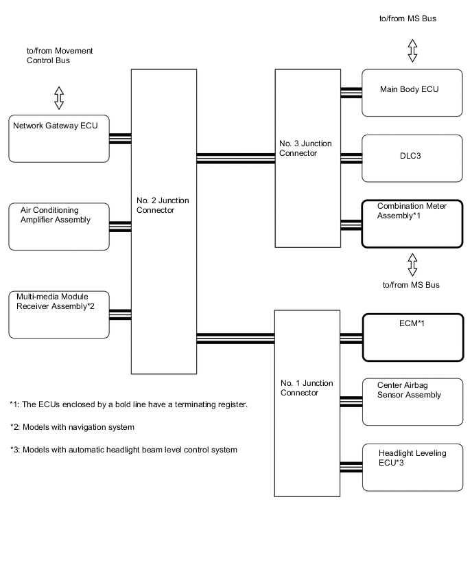
Figure 2. Movement Control Bus (LHD Models)
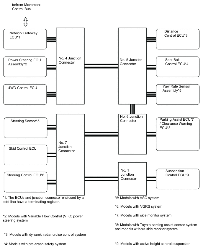
Figure 3. MS Bus (LHD Models)
-
Models without Network Gateway ECU
Figure 4. V Bus (LHD Models)
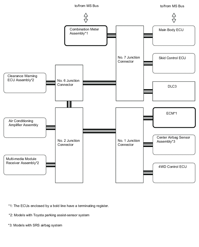
Figure 5. MS Bus (LHD Models)
-
-
LAYOUT OF MAIN COMPONENTS
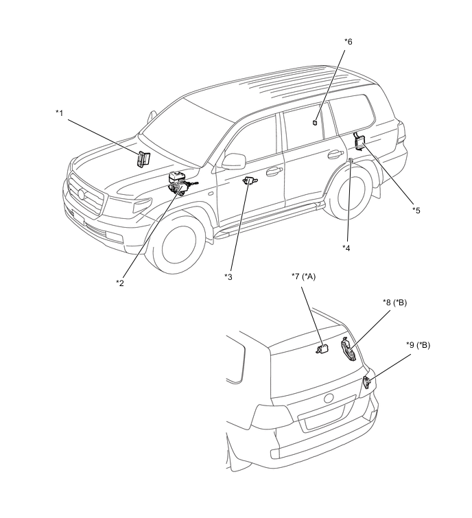
*A Models with Tire Pressure Warning System *B Models with Power Back Door System *1 ECM *2 Hydraulic Brake Booster Assembly
-
Skid Control ECU
*3 Outer Mirror ECU *4 No. 1 Junction Connector *5 Suspension Control ECU *6 No. 9 Junction Connector *7 Tire Pressure Warning ECU and Receiver *8 Power Back Door ECU *9 No. 2 Main Body ECU - - 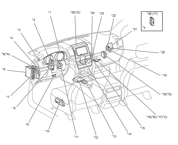
*A Models with VGRS System *B Models with Toyota Parking Assist-sensor System and Models without Side Monitor System *C Models with Parking Assist Monitor System *D Models with Rain Sensor *E Models with Navigation System *F Models with Entry and Start System *1 Combination Meter Assembly *2 Seat Belt Control ECU *3 No. 7 Junction Connector *4 No. 3 Junction Connector *5 Steering Control ECU *6 Main Body ECU (Driver Side Junction Block) *7 No. 8 Junction Connector *8 Multiplex Tilt and Telescopic ECU *9 DLC3 *10 Driver Seat ECU *11 Steering Sensor *12 Center Airbag Sensor Assembly *13 Yaw Rate Sensor Assembly *14 Air Conditioning Amplifier Assembly *15 No. 11 Junction Connector *16 Clearance Warning ECU *17 Parking Assist ECU *18 Windshield Wiper ECU *19 Network Gateway ECU *20 No. 4 Junction Connector *21 4WD Control ECU *22 No. 10 Junction Connector *23 No. 2 Junction Connector *24 No. 5 Junction Connector *25 Multi-media Module Receiver Assembly *26 Certification ECU *a Refer to the Service Bulletin for the installation of the part. - - -
-
DIAGNOSIS
-
If a malfunction occurs on the CAN communication line, the ECU that is connected to the CAN communication line stores the DTC (Diagnostic Trouble Code) in its memory.
-
For details, refer to the Repair Manual
-