1VD-FTV ENGINE
-
General
-
The engine control system of the 1VD-FTV engine has the following systems:
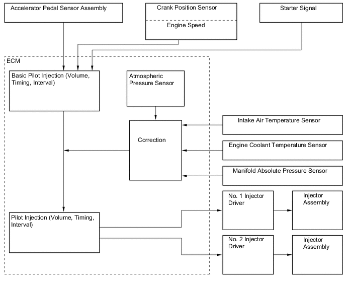
System Outline EURO 5 Except EURO 5 Fuel Injection Volume Control Based on the signals received from the sensors, the ECM determines the fuel injection volume in accordance with the engine condition. ○ ○ Fuel Injection Timing Control Based on the signals received from the sensors, the ECM determines the fuel injection timing in accordance with the engine condition. ○ ○ During Starting Control To facilitate startability, the ECM optimally controls the injection volume and injection timing during starting. ○ ○ Idle Speed Control The ECM determines the idle speed in accordance with the engine condition, and controls the fuel injection volume in order to maintain the target idle speed. ○ ○ Fuel Pressure Control Based on the signals received from the sensors, the ECM controls fuel pressure using the Suction Control Valve (SCV) and fuel pressure discharge valve in accordance with engine operating conditions. ○ - Based on the signals received from the sensors, the ECM controls fuel pressure using the (Suction Control Valve) SCV in accordance with the engine conditions. - ○ Pilot Injection Control Based on the signals received from the sensors, the ECM determines pilot injection volume/timing, and interval (between pilot injection and main injection) in accordance with the engine condition. ○ ○ Glow Plug Control Controls the length of time when the current is applied to the glow plugs in accordance with the engine coolant temperature. ○ ○ Throttle Control
-
Based on the signals received from the various sensors, the ECM determines throttle valve position in accordance with the engine conditions.
-
Fully closes the throttle valve in order to reduce vibration when the engine is stopped.
○ ○ Turbocharger Control Based on the signals received from the sensors, the ECM controls the actuator in accordance with the engine conditions. ○ - Based on the signals received from the sensors, the ECM controls the actuator via the turbo motor driver in accordance with the engine conditions. - ○ Fuel Pump Control*1 Based on the signals from the sensors, the ECM operates the fuel pump to optimally control the transfer of the fuel from the fuel sub tank sub-assembly to the fuel tank sub-assembly. - ○ EGR Control Based on the signals received from the sensors, the ECM determines the EGR volume via the EGR valve and throttle valve in accordance with the engine conditions. ○ ○*2 Engine Mounting Control When the engine speed and the vehicle speed are low, this control utilizes vacuum to soften the engine mounting characteristics in order to restrain the engine vibration. ○ ○ Oil Maintenance Management When the ECM determines engine oil deterioration, the engine oil change reminder light turns on to inform the driver. ○ - Starter Control (Cranking Hold Function)*3 Once the engine switch is pushed, this control continues to operate the starter until the engine is started. ○ ○ Air Conditioner Cut-off Control By controlling the air conditioner compressor on or off in accordance with the engine conditions, driveability is maintained. ○ ○ Catalyst Support Control Based on the signals received from the sensors, the ECM controls the exhaust fuel addition injector assembly to purify the Particulate Matter (PM) that is captured in the filter with catalyst. ○ - Air Fuel Ratio Sensor Heater Control Maintains the temperature of the air fuel ratio sensors at an appropriate level to increase the detection accuracy of the exhaust gas oxygen concentration. ○ - Engine Immobiliser Prohibits fuel injection if an attempt is made to start the engine with an invalid key. ○ ○ Diagnosis When the ECM detects a malfunction, it records the malfunction and memorizes information related to the fault. ○ ○ Fail-safe When the ECM detects a malfunction, it stops or controls the engine according to the data already stored in the memory. ○ ○ Brake Override System The driving torque is restricted when the brake pedal is depressed while the accelerator pedal is depressed. (For the Activation Conditions and Inspection Method, refer to the Repair Manual.) ○ ○ ○: Applicable
-: Not applicable
*1: Models with dual fuel tank
*2: Models compliant with EURO 2, EURO 3 and EURO 4 emission regulations
*3: Models with entry and start system
-
-
-
Construction
-
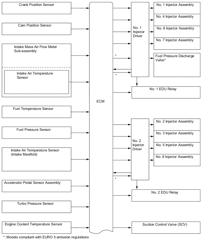
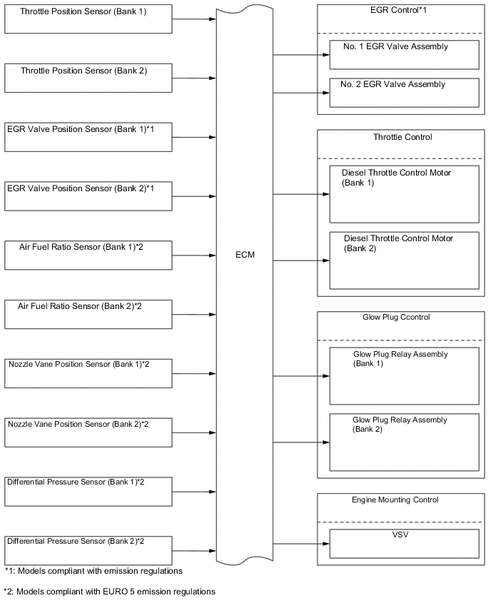
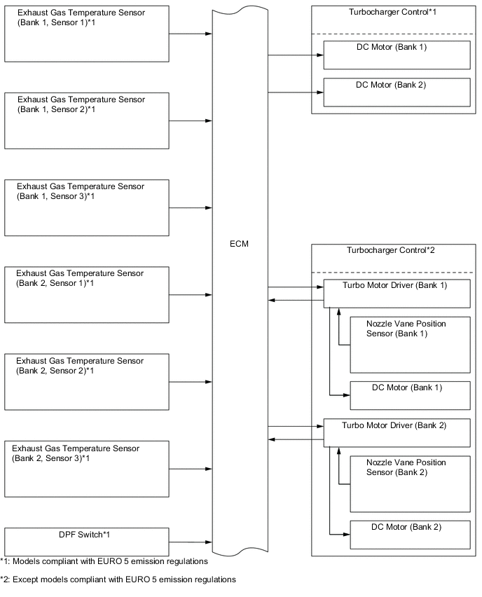
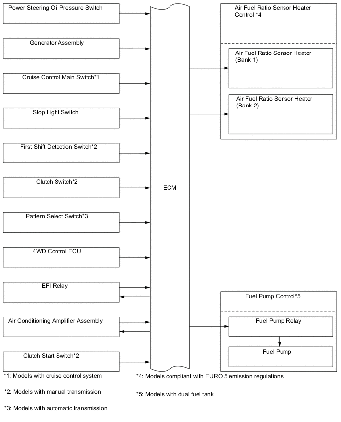
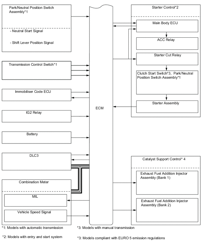
The configuration of the engine control system is as shown in the following chart.
-
-
Layout of Main Components
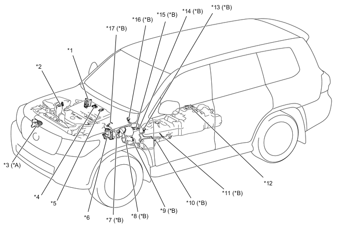
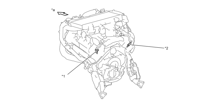
*A Except Models Compliant with EURO 5 Emission Regulations *B Models Compliant with EURO 5 Emission Regulations *1 ECM *2 Intake Mass Air Flow Meter Sub-assembly
-
Intake Air Temperature Sensor
*3 Turbo Motor Driver *4 Manifold Absolute Pressure Sensor *5 Intake Air Temperature Sensor (Intake Manifold) *6 Injector Driver *7 Exhaust Gas Temperature Sensor (Bank 1, Sensor 2) *8 Exhaust Gas Temperature Sensor (Bank 2, Sensor 1) *9 Exhaust Gas Temperature Sensor (Bank 2, Sensor 2) *10 Exhaust Gas Temperature Sensor (Bank 2, Sensor 3) *11 Air Fuel Ratio Sensor (Bank 2) *12 Fuel Suction with Pump and Gauge Tube Assembly
-
Fuel Pump (Models with Dual Fuel Tank)
*13 Differential Pressure Sensor (Bank 2) *14 Air Fuel Ratio Sensor (Bank 1) *15 Exhaust Gas Temperature Sensor (Bank 1, Sensor 3) *16 Differential Pressure Sensor (Bank 1) *17 Exhaust Gas Temperature Sensor (Bank 1, Sensor 1) - - 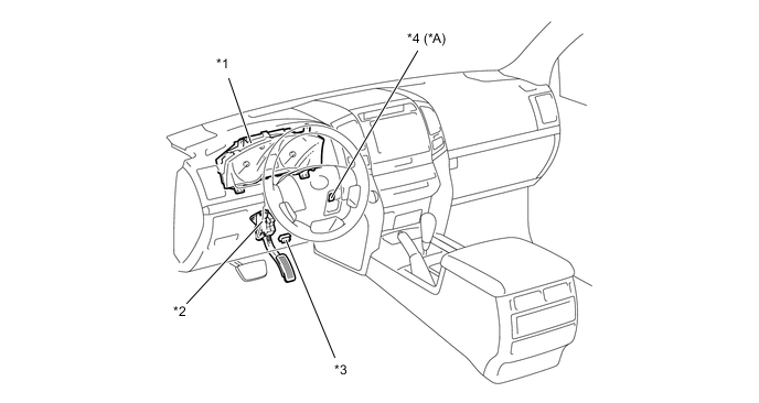
*A Models Compliant with EURO 5 Emission Regulations - - *1 Combination Meter
-
MIL
-
Multi-information Display (Models with Optitron Type Combination Meter)
*2 Accelerator Pedal Sensor Assembly *3 DLC3 *4 DPF Switch 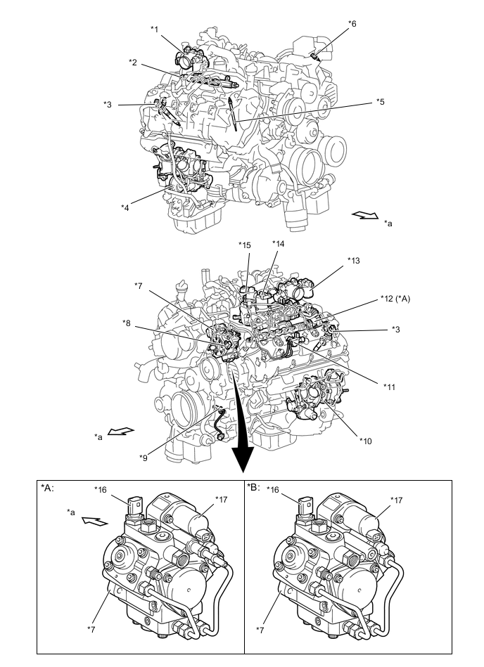
*A Models Compliant with EURO 5 Emission Regulations *B Except Models Compliant with EURO 5 Emission Regulations *1 Diesel Throttle Body Assembly (Bank 1)
-
Throttle Position Sensor
-
Diesel Throttle Control Motor
*2 Fuel Pressure Sensor *3 Injector Assembly *4 Turbocharger Sub-assembly (Bank 1)
-
DC Motor
-
Nozzle Vane Position Sensor
*5 Glow Plug Assembly *6 Engine Coolant Temperature Sensor *7 Supply Pump Assembly *8 Cam Position Sensor *9 Crank Position Sensor *10 Turbocharger Sub-assembly (Bank 2)
-
DC Motor
-
Nozzle Vane Position Sensor
*11 VSV (for Engine Mount Control) *12 Fuel Pressure Discharge Valve *13 Diesel Throttle Body Assembly (Bank 2)
-
Throttle Position Sensor
-
Diesel Throttle Control Motor
*14 No. 2 EGR Valve Assembly
-
EGR Valve Position Sensor (Bank 2)
*15 No. 1 EGR Valve Assembly
-
EGR Valve Position Sensor (Bank 1)
*16 Fuel Temperature Sensor *17 SCV - - *a Front - - Figure 1. Models Compliant with EURO 5 Emission Regulations
*1 Exhaust Fuel Addition Injector Assembly (Bank 2) *2 Exhaust Fuel Addition Injector Assembly (Bank 1) *a Front - - -
-
Main Components of Engine Control System
-
General
-
The engine control system of the 1VD-FTV engine has the following system.
Component Outline Quantity Function ECM 32-bit CPU (DENSO) 1 The ECM effects overall control of the engine control system to suit the operating conditions of the engine in accordance with the signals provided by the sensors. Injector Driver DC/DC Converter 2 The injector driver is used to drive the injector assembly at high speeds. The injector driver has realized high-speed driving under high fuel pressure conditions through the use of a DC/DC converter that provides a high voltage, quick-charging system. Intake Mass Air Flow Meter Sub-assembly Hot-wire Type 1 This sensor uses a built-in hot-wire to directly detect the intake air mass and flow rate. Atmospheric Temperature Sensor Thermistor Type 1 This sensor detects the atmospheric temperature by means of an internal thermistor. Fuel Pressure Sensor Semiconductor Strain Gauge Type 1 This sensor uses built-in semiconductors to detect the internal pressure of the common-rail assembly. Manifold Absolute Pressure Sensor Semiconductor Silicon Chip Type 1 This sensor uses built-in semiconductors to detect the intake manifold pressure. Atmospheric Pressure Sensor Semiconductor Silicon Chip Type 1 This sensor, which is built into the ECM, uses semiconductors to detect the atmospheric pressure. Crank Position Sensor Pick-up Coil Type (Rotor Teeth /36-2) 1 This sensor detects the engine speed and performs the cylinder identification. Cam Position Sensor Pick-up Coil Type (Rotor Teeth /1) 1 This sensor performs the cylinder identification. Throttle Position Sensor Non-contact Type 2 This sensor detects the throttle valve opening angle. Accelerator Pedal Sensor Assembly No-contact Type 1 This sensor detects the amount of pedal effort applied to the accelerator pedal. Engine Coolant Temperature Sensor Thermistor Type 1 This sensor detects the engine coolant temperature by means of an internal thermistor. Intake Air Temperature Sensor Thermistor Type 1 This sensor detects the intake air temperature after the intercooler. Fuel TemperatureSensor Thermistor Type 1 This sensor detects the fuel temperature in the supply pump assembly by means of an internal thermistor. Suction Control Valve (SCV) Linear Solenoid Valve 1 The SCV position is controlled by the signals from the ECM, and a fuel volume that suits the SCV position is drawn into the pumping portion (plunger portion). Injector Assembly 9-hole, Solenoid Type*1 8 The injector assembly injects the fuel to the combustion chamber in accordance with the ECM signals via the injector driver. 9-hole, Piezo Type*2 Exhaust Fuel Addition Injector Assembly*2 Solenoid Type 2 (1 each bank) Injects fuel into the fuel injection passage of the cylinder head sub-assembly. To reduce PM, the ECM controls the injection timing and the injection frequency of the injectors, and activates the exhaust fuel addition injector assembly. Differential Pressure Sensor*2 - 2 (1 each bank) Monitors the differential pressure before and after the DPF to detect whether the DPF is clogged. Exhaust Gas Temperature Sensor*2 Thermistor Type 6 (3 each bank) Located before the oxidation catalyst, and before and after the DPF, these sensors detect the exhaust gas temperature. Air Fuel Ratio Sensor (Bank 1, Sensor 1)*2 - 1 Detects the oxygen concentration in exhaust gas. Air Fuel Ratio Sensor (Bank 2, Sensor 1)*2 1 *1: Except models compliant with EURO 5 emission regulations
*2: Models compliant with EURO 5 emission regulations
-
-
Intake Mass Air Flow Meter Sub-assembly
-
The intake mass air flow meter sub-assembly of diesel engine uses precise fuel injection volume control and EGR control to realize clean emission.
-
This intake mass air flow meter sub-assembly, which is a slot-in type, allows a portion of the intake air to flow through the detection area. By directly measuring the mass and the flow rate of the intake air, the detection precision is improved and the intake air resistance is reduced.
-
The intake mass air flow meter sub-assembly has a built-in atmospheric temperature sensor.
*1 Atmospheric Temperature Sensor - - 
Air Flow - -
-
-
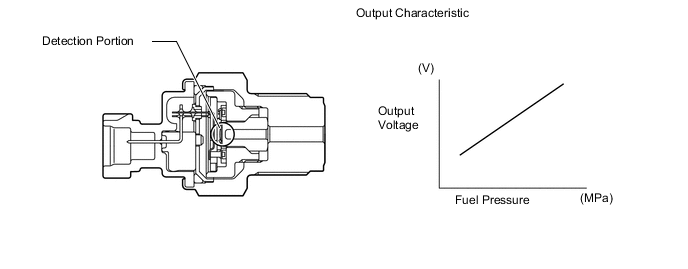
Fuel Pressure Sensor
-
The fuel pressure sensor consists of a semiconductor which utilizes the characteristic of a silicon chip that changes its electrical resistance when pressure is applied to it. This sensor is mounted on the common-rail assembly, outputs a signal that represents the fuel pressure in the common-rail assembly to the ECM, in order to constantly regulate the fuel at an optimal pressure.
-
-
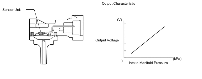
Manifold Absolute Pressure Sensor
-
The manifold absolute pressure sensor consists of a semiconductor which utilizes the characteristic of a silicon chip that changes its electrical resistance when pressure is applied to it. The sensor converts the intake air pressure into an electrical signal, and sends it to the ECM in an amplified form.
-
-
Crank Position Sensor
-
The timing rotor of the crankshaft consists of 34 teeth, with 2 teeth missing. The crank position sensor outputs the crankshaft rotation signals every 10°, and the missing teeth are used to determine the top-dead-center.
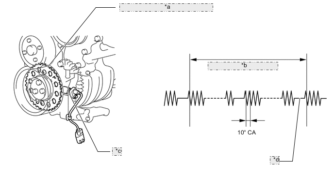
*a Timing Rotor (No.1 Crankshaft Position Sensor Plate) *b NE Signal Plate (720° CA) *c Crank Position Sensor *d 2 Teeth Missing
-
-
Cam Position Sensor
-
The cam position sensor generates one signal in every two revolutions of the crankshaft by using the timing trigger of the No. 2 camshaft timing sprocket.
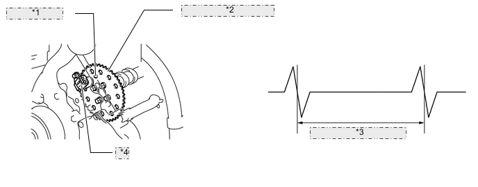
*1 Timing Trigger *2 No. 2 Camshaft Timing Sprocket *3 G Signal Plate (720° CA) *4 Cam Position Sensor
-
-
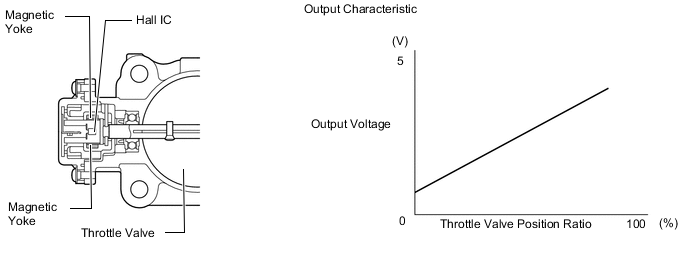
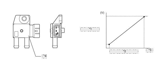
Throttle Position Sensor
-
The throttle position sensor is mounted on the diesel throttle body, to detect the opening angle of the throttle valve. The throttle position sensor converts the magnetic flux density that changes when the magnetic yoke (located on the same axis as that of the throttle valve shaft) rotates around the Hall IC into electric signals to operate the diesel throttle control motor.
-
-
Accelerator Pedal Sensor Assembly
-
The no-contact type accelerator pedal sensor assembly uses a Hall IC, which is mounted on the accelerator pedal arm.
-
A magnetic yoke is mounted at the base of the accelerator pedal arm. This yoke rotates around the Hall IC in accordance with the amount of effort that is applied to the accelerator pedal. The Hall IC converts the changes that occur in the magnetic flux into electrical signals, and outputs them in the form of accelerator pedal position signals to the ECM.
-
The Hall IC contains two circuits, one for the main signal, and the other for the sub signal. It converts the accelerator pedal position (angle) into electric signals that have differing characteristics and outputs them to the ECM.
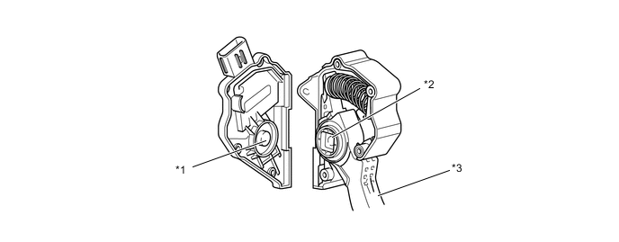
*1 Hall IC *2 Magnetic Yoke *3 Accelerator Pedal Arm - - 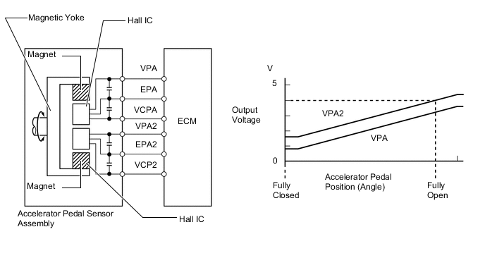
-
-
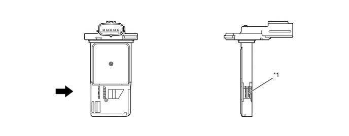
Differential Pressure Sensor
-
The differential pressure sensor measures the pressure differences between before and after the DPF with PM in order to detect clogging.
-
The sensor is mounted on the transmission. The DPF and the sensor are connected with pipes and hoses.
*1 Output Voltage *2 Differential Pressure *3 (kPa) *4 Differential Pressure Sensor
-
-
Exhaust Gas Temperature Sensor
-
An exhaust gas temperature sensor, which is a thermistor type, is installed before the oxidation catalyst, before the DPF and after the DPF, in order to detect the temperature of the exhaust gas.
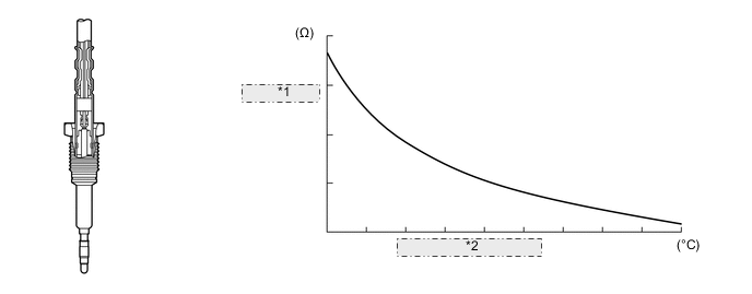
*1 Electric Resistance Value *2 Exhaust Gas Temperature
-
-
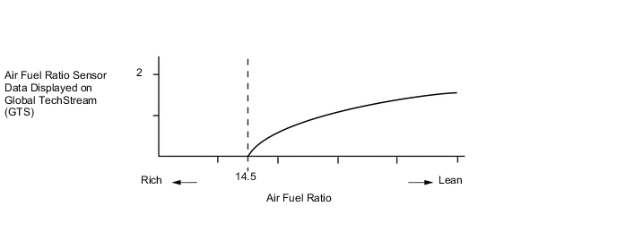
Air Fuel Ratio Sensor
-
A planar type air fuel ratio sensor is used.
-
The planar type air fuel ratio sensor uses alumina, which excels in heat conductivity and insulation, to integrate the sensor element with the heater, thus improving the warm-up performance of the sensor.
-
This sensor is based on a sensor developed for gasoline engines. The cover has been changed for diesel engine application in order to eliminate the influences of the sensor temperature and the PM. This sensor, which is mounted after the DPF, detects the air fuel ratio after the gas has been reduced.
*1 Diffusion Resistance Layer *2 Alumina *3 Platinum Electrode *4 Heater *5 Atmosphere *6 Sensor Element (Zirconia) -
The air fuel ratio sensor data is approximately proportional to the existing air fuel ratio. The air fuel ratio sensor converts the oxygen density to a current and sends it to the ECM.
-
As a result, the detection precision of the air fuel ratio has been improved. The air fuel ratio sensor data can be read using an Global TechStream (GTS).
-
-
-
Fuel Injection Volume Control
-
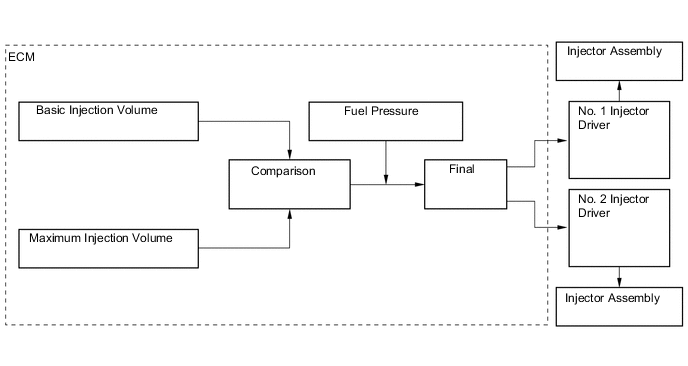
The ECM calculates two types of values: the basic injection volume and the maximum injection volume. Then, the ECM compares the basic and maximum injection volumes, and determines a smaller calculated value to be the final injection volume.
Figure 2. Basic Injection Volume
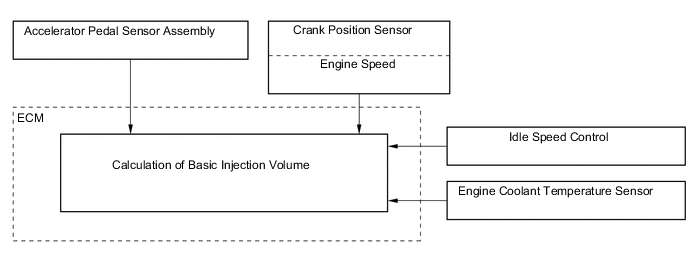
Figure 3. Maximum Injection Volume
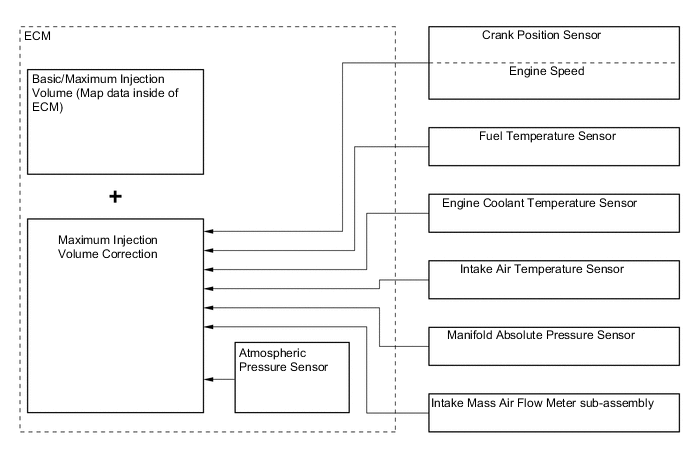
Figure 4. Final Injection Volume Decision
-
-
Fuel Injection Timing Control
-
Fuel injection timing is controlled as shown below.

-
-
During Starting Control
-
Injection Volume Control
-
The starting injection volume is determined by adjusting the basic injection volume in accordance with the starter ON signals (ON time), engine coolant temperature sensor signals and engine speed signal. When the engine is cold, the engine coolant temperature will be lower and the injection volume will be greater.
-
-
Injection Timing Control
-
To determine the starting injection timing, the target injection timing is corrected in accordance with the starter signals, engine coolant temperature, and engine speed. When the engine coolant temperature is low, if the engine speed is high, the injection timing is advanced.
*1 Starter Signal *2 Target Injection Timing Correction *3 Engine Coolant Temperature Sensor *4 Crank Position Sensor
-
-
-
Idle Speed Control
-
Idle speed is controlled as shown below.
-
-
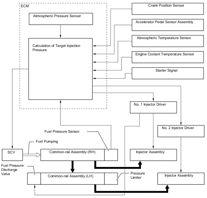
Fuel Pressure Control
-
General
-
Except Models Compliant with EURO 5 Emission Regulations
-
The ECM calculates the target injection pressure (25 MPa to 175 MPa*1, 25 MPa to 129 MPa*2) based on the engine conditions, that are the signals from the accelerator pedal sensor assembly and the crank position sensor.
-
To control fuel pressure, signals sent to Suction Control Valve (SCV) of the supply pump assembly regulate the pumping volume, so that the pressure detected by the fuel pressure sensor matches the target injection pressure.
-
*1: Models compliant with EURO 4 emission regulations
-
*2: Except models compliant with EURO 4 emission regulations
-
-
Models Compliant with EURO 5 Emission Regulations
-
The ECM calculates the target injection pressure (32 MPa to 200 MPa) based on the signals from the accelerator pedal sensor assembly and the crank position sensor.
-
To control fuel pressure, signals sent to the Suction Control Valve (SCV) of the supply pump assembly regulate the suction volume, and signals sent to the fuel pressure discharge valve of the common-rail assembly via the No. 1 injector driver regulate the discharge volume, so that the pressure detected by the fuel pressure sensor matches the target injection pressure.
-
A pressure limiter mechanically relieves the pressure if the internal pressure of the common-rail assembly rises abnormally.
-
-
-
System Operation
-
General
-
The ECM controls the opening of the Suction Control Valve (SCV) in order to regulate the volume of fuel that is pumped by the supply pump assembly to the common-rail assembly. Consequently, the fuel pressure in the common-rail assembly is controlled to the target injection pressure.
-
-
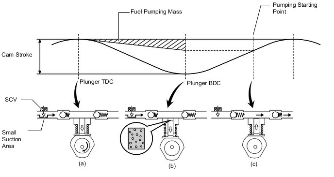
SCV Opening Small
-
(a) When the opening of the SCV is small, the fuel suction area is kept small, which decrease the transferable fuel quantity.
-
(b) The plunger strokes fully, however, the suction volume becomes small due to the small suction area. Therefore, the difference of the volume between the geometry volume and the suction volume is in vacuum condition.
-
(c) Pumping will start at the time when the fuel pressure has become higher than the common-rail assembly pressure.
-
-
SCV Opening Large
-
(a) When the opening of the SCV is large, the fuel suction area is kept large, which increase the transferable fuel quantity.
-
(b) If the plunger strokes fully, the suction volume will increase because the suction area is large.
-
(c) Pumping will start at the time when the fuel pressure has become higher than the common-rail assembly pressure.
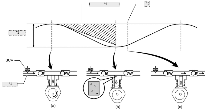
*1 Fuel Pumping Mass *2 Pumping Starting Point *3 Cam Stroke *4 Large Suction Area -
-
-
-
Pilot Injection Control
-
Pilot injection is a method that provides auxiliary fuel injection before the main injection takes place. The purpose of pilot injection is to gently start the combustion of the fuel of the main injection in order to reduce combustion noise.
State Pilot Injection Ordinary Injection Fuel Injection 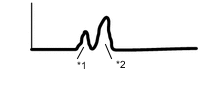
*1 Pilot Injection *2 Main Injection 
Combustion Pressure 
-
During pilot injection, the pilot injection volume, timing, and interval (between pilot injection and main injection) are controlled as shown below.
-
-
Throttle Control
-
The opening of the throttle valve is controlled by the ECM in accordance with engine conditions. As a result, the noise that is generated during idling and deceleration, as well as the noise and vibration that are generated when the engine is stopped, have been reduced.
*1 Diesel Throttle Control Motor *2 ThrottlePosition Sensor *3 ECM *4 Atmospheric Pressure Sensor *5 Engine Speed *6 Vehicle Speed *7 Engine Coolant Temperature *8 Intake Air Temperature *9 Accelerator Pedal Position *10 Intake Air Pressure *11 Starter Signal - -
-
-
Turbo Charger Control
-
General
-
Except Models Compliant with EURO 5 Emission Regulations
-
The ECM controls nozzle vane positions in the turbocharger sub-assemblies on each bank via the turbo motor drivers in order to obtain the calculated target turbo pressure appropriate to the engine operation conditions.
-
The ECM calculates the optimal nozzle vane position in accordance with the driving conditions (such as engine speed, injection volume, atmospheric pressure and engine coolant temperature), and sends a target nozzle vane position signal to each turbo motor driver. The turbo motor driver controls the nozzle vane position in accordance with this signal and the actual nozzle vane position signal provided by the nozzle vane position sensor.
Figure 5. System Diagram
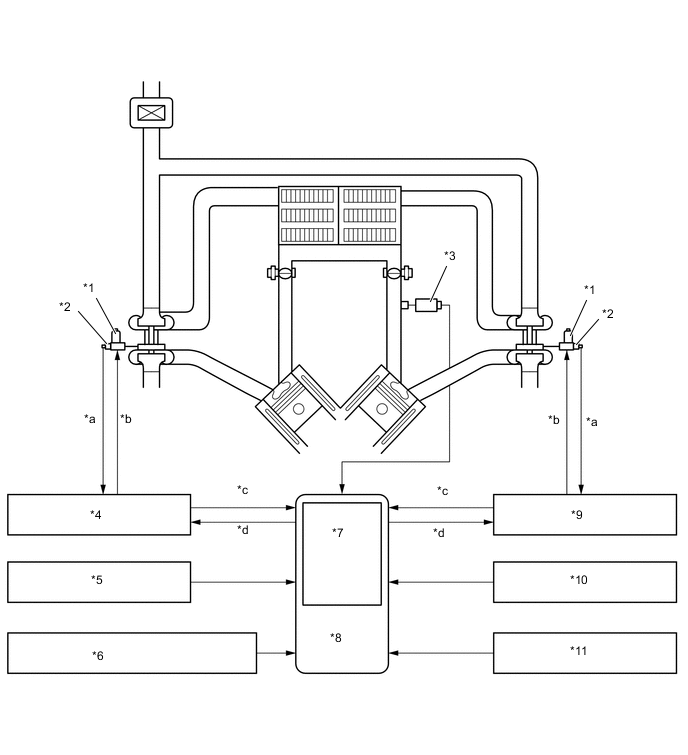
*1 DC Motor *2 Nozzle Vane Position Sensor *3 Manifold Absolute Pressure Sensor *4 No. 1 Turbo Motor Driver *5 Crank Position Sensor *6 Accelerator Pedal Sensor Assembly *7 Atmospheric Pressure Sensor *8 ECM *9 No. 2 Turbo Motor Driver *10 Engine Coolant Temp. Sensor *11 Intake Air Temp. Sensor - - *a Actual Nozzle Vane Position *b Nozzle Vane Position Control *c Turbocharger Control Status *d Target Nozzle Vane Position -
-
Models Compliant with EURO 5 Emission Regulations
-
The ECM controls the actuator directly.
-
The ECM controls nozzle vane positions in the turbocharger sub-assemblies on each bank in order to obtain the calculated target turbo pressure appropriate to the engine operation conditions.
-
The ECM calculates the optimal nozzle vane position in accordance with the driving conditions (engine speed, injection volume, atmospheric pressure, and engine coolant temperature etc.), and controls the nozzle vane position in accordance with the optimal nozzle vane position and the actual nozzle vane position signal provided by the nozzle vane position sensor.
Figure 6. System Diagram
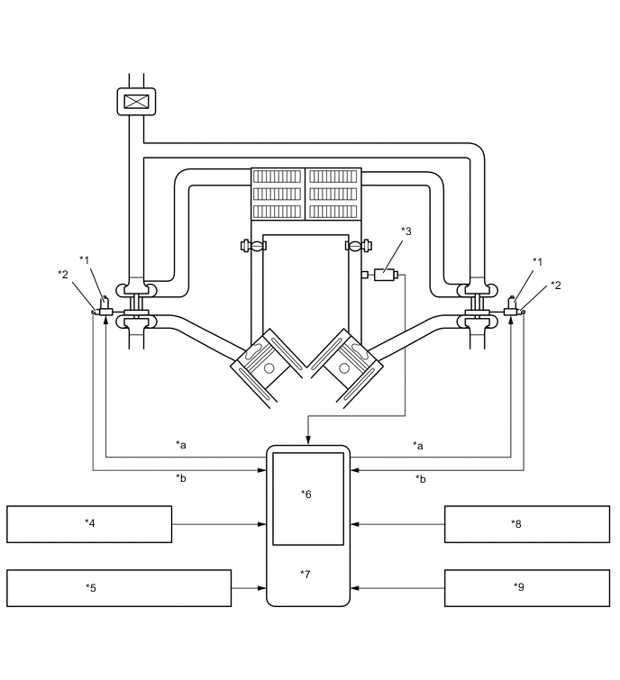
*1 DC Motor *2 Nozzle Vane Position Sensor *3 Manifold Absolute Pressure Sensor *4 Crank Position Sensor *5 Accelerator Pedal Sensor Assembly *6 Atmospheric Pressure Sensor *7 ECM *8 Engine Coolant Temp. Sensor *9 Intake Air Temp. Sensor - - *a Actual Nozzle Vane Position *b Nozzle Vane Position Control -
-
-
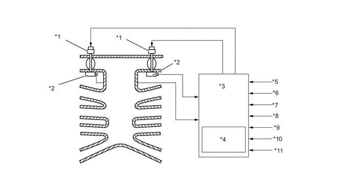
Construction
-
General
-
Variable nozzle vane device is established on the turbine wheel (exhaust) side, and consisted of a DC motor, nozzle vane position sensor, linkage, drive arm, unison ring, driven arms and nozzle vanes.
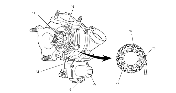
*1 Turbine Wheel *2 Linkage *3 Nozzle Vane Position Sensor *4 DC Motor *5 Nozzle Vane *6 Driven Arm *7 Unison Ring *8 Drive Arm -
-
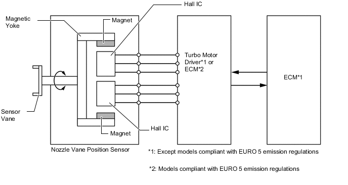
Nozzle Vane Position Sensor
-
The nozzle vane position sensor consists of a Hall IC and a magnetic yoke that rotates in unison with the movement of the linkage that actuates the nozzle vane. The nozzle vane position sensor converts the changes in the magnetic flux that are caused by the rotation of the DC motor (hence, the rotation of the magnetic yoke) into electric signals, and outputs them to the turbo motor driver*1 or ECM*2. The turbo motor driver determines the actual nozzle vane position from the electric signals in order to calculate the target nozzle vane position.*1
-
*1: Except models compliant with EURO 5 emission regulations
-
*2: Models compliant with EURO 5 emission regulations
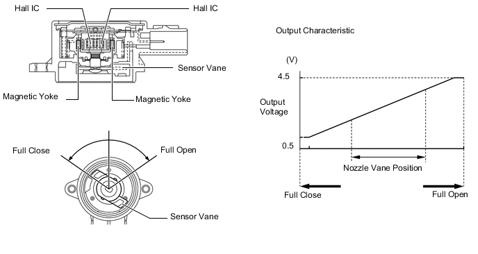
Figure 7. System Diagram
-
-
-
Operation
-
At Engine Low Speed Range
-
When the engine is running in a low speed range, the DC motor pulls up the linkage by a signal from the turbo motor driver*1 or ECM*2. The tip of the linkage rotates the unison ring counterclockwise through a drive arm. The unison ring contains a driven arm, which is placed through the cutout portion of the unison ring. This driven arm also moves in the direction of the rotation of the unison ring. The fulcrum of the driven arm is an axis that is integrated with the nozzle vane behind the plate. When the driven arm moves counterclockwise, the nozzle vane moves toward the closing direction. This results in increasing the velocity of the exhaust gas flowing to the turbine, as well as the speed of the turbine. As a result, torque is improved when the engine is running at low speeds.
-
*1: Except models compliant with EURO 5 emission regulations
-
*2: Models compliant with EURO 5 emission regulations
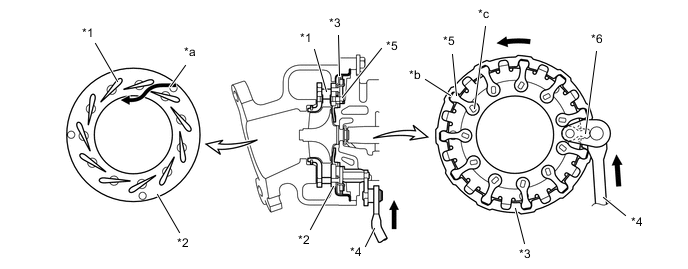
*1 Nozzle Vane *2 Plate *3 Unison Ring *4 Linkage *5 Driven Arm *6 Drive Arm *a Gas Flow *b Cutout Portion *c Fulcrum - - -
-
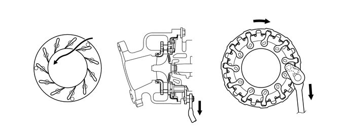
At Engine Medium-to-High Speed Range
-
When the engine is running in a medium-to-high speed range, the DC motor presses down the linkage by a signal from the turbo motor driver*1 or ECM*2. With this, the driven arm moves clockwise and this opens the nozzle vane and holds the specified supercharging pressure. Thus, lowering the back pressure and improving the output and fuel consumption.
-
*1: Except models compliant with EURO 5 emission regulations
-
*2: Models compliant with EURO 5 emission regulations
-
-
-
-
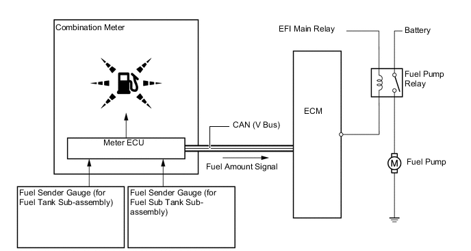
Fuel Pump Control
-
The ECM operates the fuel pump in accordance with signals from the meter ECU, which indicate the fuel amount in the fuel tanks (calculated by signals from fuel sender gauges in each fuel tank), to transfer fuel from the fuel sub tank sub-assembly to the fuel tank sub-assembly using the jet pump for fuel transfer.
-
The meter ECU determines if the fuel pump control system is malfunctioning based on the fuel amount in the fuel tank sub-assembly and fuel sub tank sub-assembly. When the meter ECU detects that the fuel amount in the fuel tank sub-assembly is small (20.7 liters [21.9 US qts, 18.2 Imp. qts] or less) and the amount in the fuel sub tank sub-assembly is large (7.8 liters [8.2 US qts, 6.9 Imp. qts] or more), it determines that fuel has not been transferred from the fuel sub tank sub-assembly to the fuel tank sub-assembly. The meter ECU then blinks the low fuel warning light in the combination meter to inform the driver of the fuel pump control system malfunction. In addition, the master warning light comes on, the buzzer sounds and the warning message (Check Fuel System) is displayed on the multi-information display on models with optitron display type combination meter.
-
-
EGR Control
-
This system is designed to reduce and control NOx formation due to a slight reduction of peak temperature in the engine combustion chamber, which is accomplished by introducing a small amount of inert gas into intake manifold.
-
By sensing the engine driving conditions and actual amount of the EGR valve opening, the ECM operates the EGR valve and diesel throttle control motor, and regulates the amount of exhaust gas.
Figure 8. System Diagram
*1 EGR Valve Position Sensor *2 No. 1 EGR Valve *3 EGR Cooler *4 Diesel Throttle Control Motor *5 No. 2 EGR Valve *6 ECM *7 Atmospheric Pressure Sensor *8 Accelerator Pedal Sensor Assembly *9 Crank Position Sensor *10 Intake Mass Air Flow Meter sub-assembly *11 Engine Coolant Temperature Sensor *12 AtmosphericTemperature Sensor *13 Manifold Absolute Pressure Sensor - - Exhaust Gas 
Intake Air
-
-
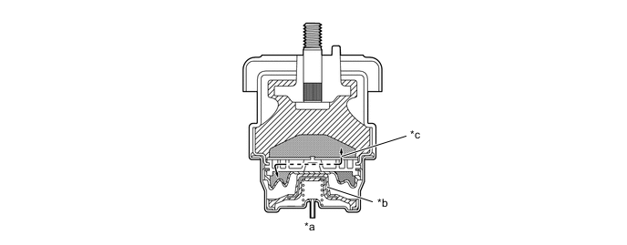
Engine Mounting Control
-
General
-
When the engine speed and the vehicle speed are low, this engine mounting utilizes the vacuum from the vacuum pump to move the diaphragm inside the mount, which switches the passage for the fluid sealed in the fluid chambers. By softening the damping characteristics of the mounting in this manner, the mounting restrains the engine vibration.
*1 Engine *2 Vacuum Pump *3 Electrical Hydraulic Type Engine Mounting *4 VSV *5 ECM *6 Vehicle Speed Signal *7 Crank Position Sensor - -
-
-
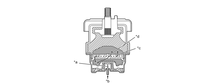
Construction
-
This engine mounting consists primarily of the rubber portion, No. 1 fluid chamber, No. 2 fluid chamber, and diaphragm. Fluid is sealed in the No. 1 and No. 2 fluid chambers.
-
This engine mounting obtains a vacuum from the vacuum pump via the VSV. It utilizes the vacuum to pull the diaphragm down in order to open or close the passages that connect the No. 1 and No. 2 fluid chambers.
-
The No. 1 and No. 2 fluid chambers use two fluid passages: the No. 1 fluid passage that is always connected regardless of whether the diaphragm is open or closed; and the No. 2 fluid passage that is connected only when the diaphragm is open. The fluid flows back and forth between the No. 1 and No. 2 fluid chambers through these two passages in order to restrain the vibration.
*1 Rubber *2 Diaphragm *a No.2 Fluid Passage *b No. 1 Fluid Passage *c Vacuum Intake *d No. 2 Fluid Chamber *e No. 1 Fluid Chamber *f Fluid
-
-
Operation
-
General
-
When the ECM determines that the engine speed and the vehicle speed are low, it controls the introduction of vacuum from the vacuum pump to the engine mounting by turning the VSV ON or OFF.
-
A hysteresis is provided for both the engine speed and the vehicle speed at the point in which the VSV switches from ON to OFF.
-
While the engine is cranking, the VSV is OFF.
-
-
When the VSV is OFF
-
When the ECM determines that the engine speed and vehicle speed exceed the specified value, it stops the introduction of vacuum into the engine mounting by turning the VSV OFF.
-
When no vacuum is introduced into the engine mounting, the diaphragm does not move, so the No. 1 fluid passage remains closed. In this state, the fluid passes only through the No. 1 fluid passage in order to flow back and forth between the No. 1 and No. 2 fluid chambers.
*a No Vacuum Introduced *b Diaphragm Stopped *c Flow of Fluid in No. 1 Fluid Passage - - -
-
When the VSV is ON
-
When the ECM determines that the engine speed and the vehicle speed are equal to or less than the specified value, it turns the VSV ON to introduce vacuum into the engine mounting.
-
When a vacuum is introduced into the engine mounting, it pulls the diaphragm down, causing the No. 2 fluid passage to open. As a result, a large volume of fluid flows back and forth between the No. 1 and No. 2 fluid chambers, thus minimizing the fluid resistance and softening the engine mounting characteristics.
*a Diaphragm Descends *b Vacuum Introduced *c Flow of Fluid in No. 1 Fluid Passage *d Flow of Fluid in No. 2 Fluid Passage -
-
-
-
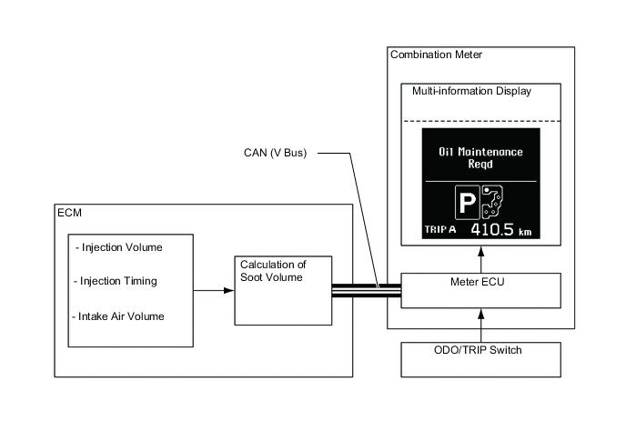
Oil Maintenance Management System
-
General
-
In this oil maintenance management system, the soot volume in the engine oil is calculated based on the engine operating conditions. Based on the calculated soot volume, the ECM displays an "Oil Maintenance Reqd" warning on the multi-information display to inform the driver when it is necessary to change the engine oil.
-
The ECM calculates soot volume from the injection volume, injection timing and intake air volume in order to operate this system.
Figure 9. System Diagram
Tech Tips
Since this system is controlled based on engine operating conditions, the "Oil Maintenance Reqd" warning may be displayed before driving 30000 km (the maximum travel distance after oil maintenance). If the "Oil Maintenance Reqd" warning is displayed, immediately replace the oil and oil filter.
-
-
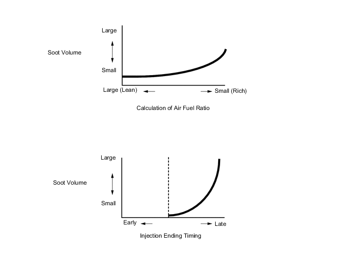
Soot Volume Calculation Method
-
The soot volume largely depends on injection ending timing and air fuel ratio. The ECM calculates soot volume from this information as shown in the graphs below.
Tech Tips
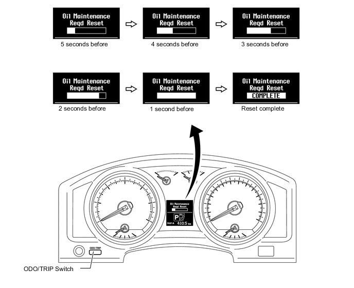
The accumulated soot volume memorized in ECM can be reset using the following procedures.
-
Switch the power source to IG-ON. Then, use the ODO/TRIP switch to turn ON the "TRIP A" display on the multi-information display.
-
Switch the power source to OFF. While pushing the ODO/TRIP switch, switch the power source to IG-ON.
-
With the power source in the IG-ON mode, keep holding the ODO/TRIP switch (for at least five seconds) with the multi-information display counting down as shown below.
-
When the resetting is completed, the multi-information display will display "COMPLETE" for one second and the buzzer built into the combination meter will sound.
-
-
-
-
Catalyst Support Control
-
General
-
This control makes the ECM control the exhaust fuel addition injector assembly to purify the Particulate Matter (PM) captured in the filter with catalyst.
The ECM judges the Diesel Particulate Filter (DPF) condition based on injection timing, injection volume, signals from various sensors to control the injector assemblies and exhaust fuel addition injector assemblies for catalyst support control.
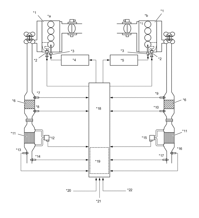
*1 Cylinder Head *2 Exhaust Fuel Addition Injector Assembly *3 Injector Assembly *4 No. 2 Injector Driver *5 No. 1 Injector Driver *6 Oxidation Catalyst *7 Exhaust Gas Temperature Sensor (Bank 2, Sensor 1) *8 Exhaust Gas Temperature Sensor (Bank 2, Sensor 2) *9 Exhaust Gas Temperature Sensor (Bank 1, Sensor 1) *10 Exhaust Gas Temperature Sensor (Bank 1, Sensor 2) *11 DPF *12 Differential Pressure Sensor (Bank 2) *13 Exhaust Gas Temperature Sensor (Bank 2, Sensor 3) *14 Air Fuel Ratio Sensor (Bank 2) *15 Differential Pressure Sensor (Bank 1) *16 Exhaust Gas Temperature Sensor (Bank 1, Sensor 3) *17 Air Fuel Ratio Sensor (Bank 1) *18 ECM *19 Atmospheric Pressure Sensor *20 Intake Mass Air Flow Meter Sub-assembly *21 DPF Switch *22 Engine Coolant Temperature Sensor *a LH *b RH
-
-
Operation
-
The DPF captures Particulate Matter (PM) in the exhaust gas to purify the exhaust gas. When the temperature of the DPF increases, the PM which has accumulated in the DPF is oxidized and emitted as CO2 and H2O.
-
If the PM which has accumulated in the DPF exceeds an expected amount, the temperature may be in danger of becoming extraordinarily high when the accumulated PM is oxidized, and there may be an abnormal increase in DPF pressure loss, which could lead to engine damage. For this reason, PM regeneration is necessary to regularly oxidize the PM accumulated in the DPF.
-
The ECM calculates the state of engine combustion via signals from each sensor. Based on this, the ECU calculates the amount of PM that has accumulated in the DPF ("A"). The ECM also uses signals from the exhaust gas temperature sensor to calculate the amount of accumulated PM that has been reduced by oxidation ("B"). In addition, the ECM calculates the amount of PM accumulated in the DPF based on "A" and "B".
-
When the amount of PM accumulated in the DPF exceeds a predetermined volume, PM regeneration will be forcibly performed to oxidize the PM. If the PM accumulation amount exceeds the predetermined volume, or if the output value of the differential pressure sensor exceeds a predetermined value, the ECM changes the combustion control in the following order: it increases the exhaust gas temperature, forcibly increases the DPF temperature by injecting the fuel from the exhaust fuel addition injector assemblies and oxidizes the PM accumulated in the DPF.
-
PM regeneration is automatically performed to keep the DPF normal. However, the DPF temperature cannot be increased enough to perform PM regeneration when driving at an extremely low speed or when driving for an extraordinarily short time. As this situation could be hazardous to the DPF if it continues for a long time, a warning needs to be given to the driver. At this time, "DPF FULL SEE OWNER'S MANUAL" will be displayed on the multi-information display as a warning message.
-
If the warning message is displayed, the driver can perform PM regeneration by driving at an appropriate speed or using the DPF switch with the vehicle idling. The message will disappear when the accumulated PM in the DPF decreases to the normal level.
-
When driving while "DPF FULL SEE OWNER'S MANUAL" is being displayed, "DPF FULL ENGINE SERVICE REQUIRED" will be displayed on the multi-information display. In this case, the driver can conduct PM regeneration using the DPF switch while idling.
-
In addition, if the driver keeps driving without conducting PM regeneration even though the warning message is displayed, PM will keep accumulating in the DPF which could cause a hazardous situation. In this case, the ECM controls the engine output and torque to protect the engine, and the MIL will turn on. In this situation, PM regeneration is not possible, and the driver will have to replace the DPF at a Toyota dealer.
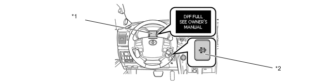
*1 Multi-information Display *2 DPF Switch Tech Tips
-
The ECM confirms activation of the oxidation catalyst by the output value of the exhaust gas temperature sensor exceeding the predetermined value.
-
When replacing the front exhaust pipe with a new one, it is necessary to perform initialization of the DPF deteriorate data history in the ECM by using a Global TechStream (GTS).
-
When replacing the ECM with a new one, it is necessary to read DPF deteriorate data history from the installed ECM and then transfer that data history to the new ECM by using a Global TechStream (GTS). When the DPF deteriorate data history is not transferred, Diagnostic Trouble Code (DTC) is stored in the ECM, and the MIL comes on.
-
When replacing both the front exhaust pipe and the ECM, it is necessary to perform initialization of the DPF deteriorate data history in the ECM using a Global TechStream (GTS). When DPF deteriorate history initialization is not performed, DTC is stored in the ECM and the MIL comes on.
-
-
-
-
Diagnosis
-
When the ECM detects a malfunction, the ECM makes a diagnosis and memorizes the failed section. Furthermore, the MIL in the combination meter illuminates or blinks to inform the driver.
-
The ECM will also store the Diagnostic Trouble Code (DTC) of the malfunctions. The DTC can be accessed by using the Global TechStream (GTS).
-
For details, refer to the Repair Manual.
Tech Tips
To clear the DTC that is stored in the ECM, use the Global TechStream (GTS), disconnect the battery terminal or remove the EFI MAIN fuse for 1 minute or longer.
-
-
Fail-safe
-
When a malfunction is detected at any of the sensors, there is a possibility of an engine or other malfunction occurring if the ECM were to continue to control the engine control system in the normal way. To prevent such a problem, the fail-safe function of the ECM either relies on the data stored in memory to allow the engine control system to continue operating, or stops the engine if a hazard is anticipated. For details, refer to the Repair Manual.
-