1VD-FTV ENGINE
-
General
-
A compact and lightweight segment conductor type generator is used on all models.
-
A SC6 type generator is provided. The cross sectional area of the segment conductors on a stator in this generator has been increased, which reduces the electrical resistance of the stator, generates high power output, and achieves a higher efficiency. This type uses an aluminum die-casting rectifier unit and also provides fins on the rectifier to improve heat dissipation.*
-
*: Models with towing package for Europe
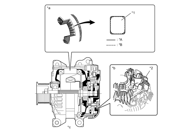
*A SC6 Type *B Conventional Type *1 Segment Conductor *2 Fin *a Stator Portion *b Rectifier Portion *c Generator Cross Section - - Specifications Type SC1 SC2 SC6 Destination G.C.C. Countries Europe*2 Europe*4 General Countries*1 Australia General Countries*3 Rated Voltage 12 V 12 V 12 V Rated Output 130 A 150 A 180 A *1: Except models for Argentina and models with towing package
*2: Models for India and Morocco
*3: Models for Argentina and models with towing package
*4: Except models for India and Morocco
-
-
-
Construction and Operation
-
This generator uses a joined segment conductor system, in which multiple segment conductors are welded together at the stator. Compared to the conventional winding system, the electrical resistance is reduced due to the shape of the segment conductors, and their arrangement helps to make the generator more compact.
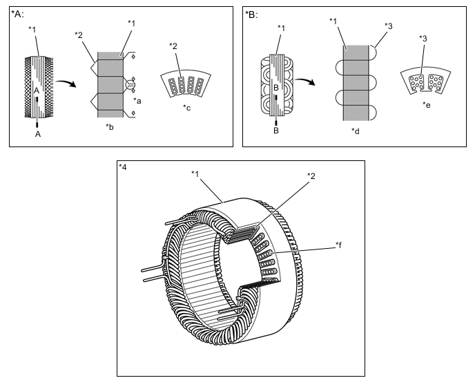
*A Segment Conductor Type Generator *B Conventional Type Generator *1 Stator *2 Segment Conductor *3 Conductor Wire *4 Stator of Segment Conductor Type Generator *a Joined *b Joined Segment Conductor System *c A - A CrossSection *d Winding System *e B - B CrossSection *f Cross Section Figure 1. Wiring Diagram
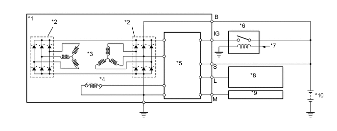
*1 Generator *2 Rectifier *3 Stator *4 Rotor *5 Regulator *6 IG1 Relay *7 Main Body ECU *8 Combination Meter
-
Discharge Warning Light
*9 ECM *10 Battery -
-
-
Dual Winding System
-
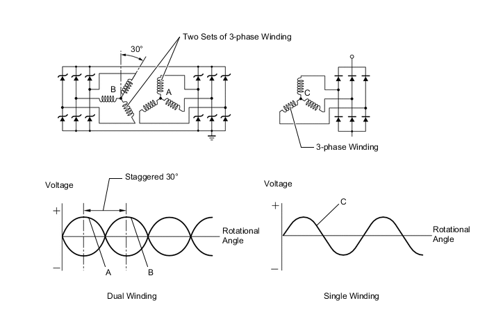
A dual winding system is used. This system consists of two sets of three-phase windings whose phases are staggered 30°. This system results in the reduction of both electrical noise (ripple and spike), and magnetic noise (a hum that is heard as generator load is increased). This system significantly suppresses noise at the source (generator). Because the waves that the respective windings generate have opposite polarities, magnetic noise is reduced. The magnetic noise is significantly reduced, but the electrical power generated does not cancel itself out due to the use of separate rectifiers. The opposite polarities that are generated can be seen below.
-