1VD-FTV ENGINE
-
General
-
A cyclone pre-cleaner is provided on all models except European models.*1
-
A snorkel air cleaner is used. The cool air intake duct of the snorkel air cleaner uses an air cleaner inlet designed to prevent rainwater entry.*2
-
A diesel throttle body equipped with a rotary solenoid type diesel throttle control motor is used.
-
An air-cooled intercooler is used.*3
-
An EGR control is used.*4.
-
A variable nozzle vane type turbocharger driven by a DC motor is used in each bank.
-
A stainless steel exhaust pipe is used for weight reduction and improved rust resistance.
-
An oxidation catalysts are used.*4
-
A Diesel Particulate Filters (DPF) are used.*5
-
*1: Models with pre-cleaner
-
*2: Optional equipment on models for Australia and general countries
-
*3: Models with intercooler
-
*4: Models compliant with emission regulations
-
*5: Models compliant with EURO 5 emission regulations
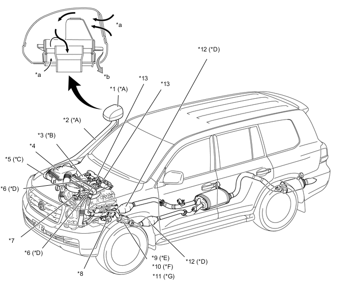
*A Models with Snorkel Air Cleaner *B Models with Intercooler *C Models with Pre-cleaner *D Models Compliant with Emission Regulations *E Models Non-compliant with Emission Regulations and Models Compliant with EURO2 and EURO 3 Emission Regulations *F Models Compliant with EURO4 Emission Regulations *G Models Compliant with EURO5 Emission Regulations - - *1 Air Cleaner Inlet *2 Cool Air Intake Duct *3 Intercooler *4 Air Cleaner *5 Pre-cleaner *6 EGR Valve *7 Exhaust Manifold *8 No. 2 Turbocharger Sub-assembly *9 Turbine Outlet Elbow LH *10 Monolithic Converter Assembly LH (Oxidation Catalyst) *11 DPF *12 Oxidation Catalyst *13 Diesel Throttle Body - - *a Air *b Rainwater -
-
-
Air Cleaner
-
A nonwoven, full-fabric type air cleaner filter element is used.
-
A cyclone pre-cleaner has been provided in the air cleaner case. This cyclone pre-cleaner has a screw shape (turbinated blade) and gathers dusts which has rather big size in a dust cup by swirling the inlet air. The dust cup is removable, so the dust gathered can be disposed.*
-
*: Models with pre-cleaner
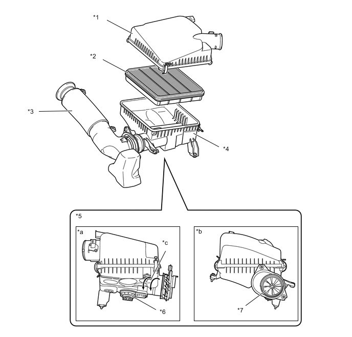
*1 Air Cleaner Cap Sub-assembly *2 Air Cleaner Filter Element Sub-assembly (Nonwoven Fabric) *3 Air Cleaner Inlet Sub-assembly *4 Air Cleaner Case Sub-assembly *5 Cyclone Pre-cleaner *6 Dust Cup *7 Turbinated Blade - - *a Rear View *b Side View *c Swirl Air Flow - - -
-
-
Diesel Throttle Body
-
Two link-less type diesel throttle bodies in which the diesel throttle control motor and the throttle position sensor are integrated are used.
-
In the diesel throttle control motor, a torque motor (rotary solenoid type) is used to control intake throttle.
-
A non-contact type throttle position sensor is used in the throttle body.
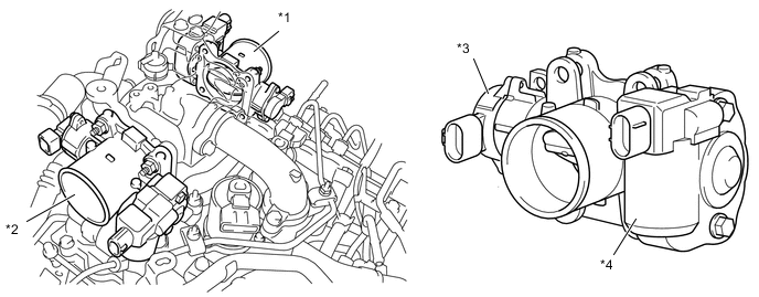
*1 Diesel Throttle Body (for bank 2) *2 Diesel Throttle Body (for bank 1) *3 Throttle Position Sensor *4 Diesel Throttle Control Motor
-
-
Intercooler
-
An air-cooled intercooler is used in order to lower the intake air temperature, improve engine performance, and to realize cleaner exhaust gas emissions. It is located directly on top of the engine.*
-
*: Models with intercooler
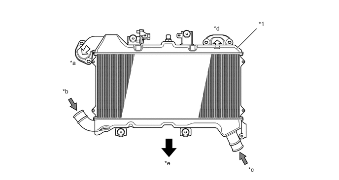
*1 Intercooler - - *a To Diesel Throttle Body (for bank 1) *b From No. 1 Turbocharger Sub-assembly *c From No. 2 Turbocharger Sub-assembly *d To Diesel Throttle Body (for bank 2) *e Front - - -
-
-
EGR Valve
-
Two linear solenoid type EGR valves are used. Also, a dual-valve mechanism is used to cancel the effects of the exhaust pressure during actuation, in order to realize quick response.
-
An EGR valve position sensor is provided in the EGR valve. This sensor enables EGR valve control at a higher level of precision by detecting the amount of lift of the EGR valve.
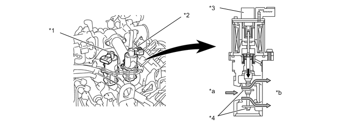
*1 No. 1 EGR Valve Assembly *2 No. 2 EGR Valve Assembly *3 EGR Valve Position Sensor *4 Dual-valve *a Exhaust Gas IN (From Exhaust Manifold) *b Exhaust Gas OUT (To Intake Manifold)
-
-
EGR Cooler
-
A water-cooled type EGR cooler is used. That lowers the exhaust gas temperature to recirculate the great amount of exhaust gas, realizing the reduction of NOx.
-
In the water-cooled type EGR cooler, water flows the five-layered gas passage to cool down.
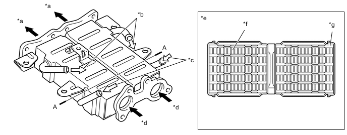
*a Exhaust Gas (To EGR Valve) *b Water OUT *c Water IN *d Exhaust Gas (From Cylinder Head) *e A-A Cross Section *f Exhaust Gas *g Water - -
-
-
Turbocharger
-
Variable nozzle vane type turbocharger sub-assembly consists primarily of a compressor wheel, turbine wheel, nozzle vane, unison ring, DC motor and nozzle vane position sensor.
-
This turbocharger sub-assembly has realized great improvements in low-speed torque, maximum output, fuel consumption, and emission reduction. These improvements have been accomplished through variable control of the nozzle vane position, and an optimal velocity of the exhaust gas inflow to the turbine at all times in response to the engine condition.
-
The ECM outputs a signal to the turbo motor driver, which actuates the DC motor, to control the nozzle vane position.*1
-
The ECM outputs a signal to the turbocharger sub-assembly, which actuates the DC motor, to control the nozzle vane position.*2
-
*1: Except models compliant with EURO 5 emission regulations
-
*2: Models compliant with EURO 5 emission regulations
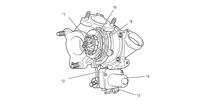
*1 Turbine Wheel *2 Linkage *3 Nozzle Vane Position Sensor *4 DC Motor *5 Unison Ring *6 Nozzle Vane -
-
The exhaust gas from the exhaust manifold goes through the nozzle vane inside the turbocharger housing, and flows to the exhaust pipe through the turbine wheel. The speed of the turbine wheel (supercharging pressure) differs depending on the flow velocity of the exhaust gas going through the turbine wheel and the flow velocity of the exhaust gas is controlled by the opening. In such a time like idling, when the exhaust gas is less, the nozzle vane is almost fully closed, but as there is a slight clearance between the vanes, the exhaust gas flows through this clearance to the exhaust pipe. Therefore, there is no bypass.

*1 Impeller *2 Nozzle Vane *3 Turbine - - 
Exhaust Gas 
Intake Air
-
-
Exhaust Manifold
-
On the models compliant with EURO 5 emission regulations, along with the use of the exhaust fuel addition injector assembly, an exhaust manifold pipe is provided to each exhaust manifold. This prevents fuel injected into the exhaust port from entering the EGR control.
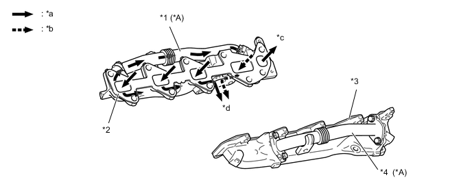
*A Models Compliant with EURO 5 Emission Regulations - - *1 No. 1 Exhaust Manifold Pipe *2 Exhaust Manifold (Bank 1) *3 Exhaust Manifold (Bank 2) *4 No. 2 Exhaust Manifold Pipe *a Exhaust Gas *b Exhaust Gas and Fuel from Exhaust Fuel Addition Injector Assembly *c To EGR Valve - -
-
-
Exhaust Pipe
-
A stainless steel exhaust pipe is used for weight reduction and rust resistance.
-
2 oxidation catalysts are used on the front exhaust pipe to clean the HC and CO.*1
-
4 oxidation catalysts are used on the front exhaust pipe to clean the HC and CO. *2
-
2 oxidation catalysts and 2 Diesel Particulate Filters (DPF) are provided in each front exhaust pipe to capture Particulate Matter (PM).*3
-
A ball joint is used to join the front exhaust pipe assembly and the center exhaust pipe assembly. As a result, a simple and reliable construction for reducing vibration has been realized.
-
*1: Models compliant with EURO 2 and EURO 3 emission regulations
-
*2: Models compliant with EURO 4 emission regulations
-
*3: Models compliant with EURO 5 emission regulations
Figure 1. Models Non-compliant with Emission Regulations
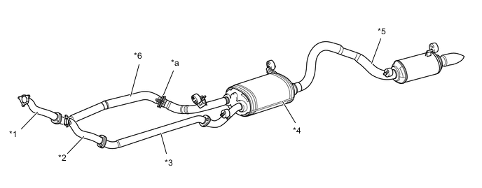
*1 Turbine Outlet Elbow RH *2 Turbine Outlet Elbow LH *3 No. 2 Front Exhaust Pipe Assembly *4 Center Exhaust Pipe Assembly *5 Tail Pipe Assembly *6 Front Exhaust Pipe Assembly *a Ball Joint - - Figure 2. Models Compliant with EURO 2 and EURO 3 Emission Regulations
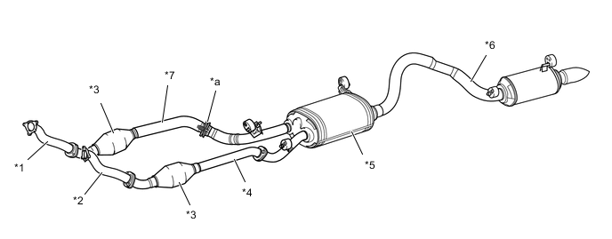
*1 Turbine Outlet Elbow RH *2 Turbine Outlet Elbow LH *3 Oxidation Catalyst *4 No. 2 Front Exhaust Pipe Assembly *5 Center Exhaust Pipe Assembly *6 Tail Pipe Assembly *7 Front Exhaust Pipe Assembly - - *a Ball Joint - - Figure 3. Models Compliant with EURO 4 Emission Regulations
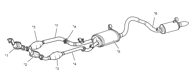
*1 Monolithic Converter Assembly RH (Oxidation Catalyst) *2 Monolithic Converter Assembly LH (Oxidation Catalyst) *3 Oxidation Catalyst *4 No. 2 Front Exhaust Pipe Assembly *5 Center Exhaust Pipe Assembly *6 Tail Pipe Assembly *7 Front Exhaust Pipe Assembly - - *a Ball Joint - - Figure 4. Models Compliant with EURO 5 Emission Regulations
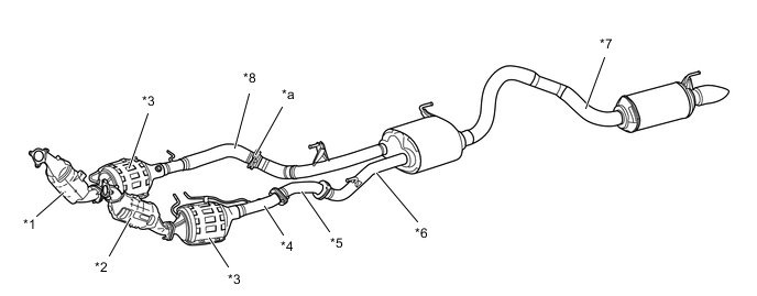
*1 Monolithic Converter Assembly RH (Oxidation Catalyst) *2 Monolithic Converter Assembly LH (Oxidation Catalyst) *3 DPF *4 No. 2 Front Exhaust Pipe Assembly *5 No. 3 Front Exhaust Pipe Assembly *6 Center Exhaust Pipe Assembly *7 Tail Pipe Assembly *8 Front Exhaust Pipe Assembly *a Ball Joint - - Figure 5. Ball Joint

*1 Front Exhaust Pipe Assembly *2 Gasket *3 Center Exhaust Pipe Assembly *4 Gasket -
-