1VD-FTV ENGINE
-
Cylinder Head Cover
-
The cylinder head cover sub-assemblies are made of plastic to reduce weight and noise.
-
Acrylic rubber, which excels in heat resistance and reliability, is used for the cylinder head cover gaskets.
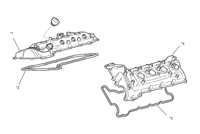
*1 Cylinder Head Cover Sub-assembly RH *2 Cylinder Head Cover Gasket RH *3 Cylinder Head Cover Gasket LH *4 Cylinder Head Cover Sub-assembly LH
-
-
Cylinder Head
-
The cylinder head is made of aluminum alloy.
-
The injector assembly has been located in the center of the combustion chamber in order to improve engine performance and clean emission.
-
The passage for the EGR is provided in the cylinder head. By cooling the exhaust gas, the great amount of exhaust gas can recirculate.
-
A vertical two-stage construction is used for the water jacket to improve cooling performance.
-
A glow plug is placed between the intake ports of each cylinder to ensure startability.
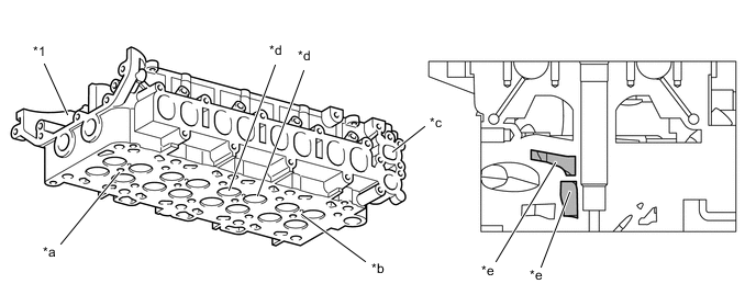
*1 Cylinder Head - - *a Injector Hole *b Glow Plug Hole *c EGR Passage *d Intake Ports *e Two-stage Water Jacket - - -
An installation hole and fuel injection passage for the exhaust fuel addition injector assembly are provided on the cylinder head.*
-
*: Models compliant with EURO 5 emission regulations
Figure 1. Models Compliant with EURO 5 Emission Regulations
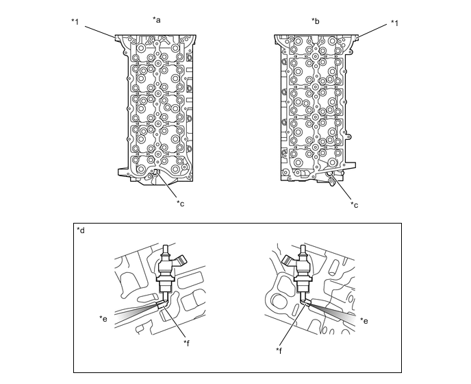
*1 Cylinder Head - - *a LH (Bank 2) *b RH (Bank 1) *c Exhaust Fuel Addition Injector Assembly Installation Hole *d Injection Passage Cross Section *e To Exhaust Port *f Injection Passage -
-
-
Cylinder Block
-
Lightweight compact graphite iron is used for the cylinder block.
-
The cylinder block has a bank angle of 90°, a bank offset of 22 mm (0.866 in.) and a bore pitch of 97 mm (3.82 in.), resulting in a compact block in its length and width even for its displacement.
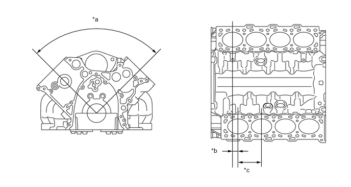
*a 90° *b 22 mm (0.866 in.) *c 97 mm (3.82 in.) - - -
The oil pump drive gear at the rear end of the cylinder block drives the oil pump and the scavenging pump in order to achieve a compact engine.
-
Four plastic region tightening bolts are used to tighten the crankshaft bearing caps together with the cylinder block stiffening plates in order to reduce vibrations.
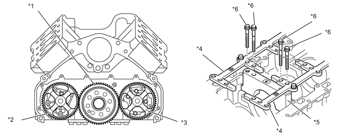
*1 Oil Pump Drive Gear *2 Scavenging Pump Assembly *3 Oil Pump Assembly *4 Cylinder Block Stiffening Plates *5 Crankshaft Bearing Cap *6 Plastic Region Tightening Bolts
-
-
Piston
-
The piston is made of aluminum alloy.
-
In conjunction with the adoption of direct injection, the piston provided with combustion chamber is used.
-
A cooling channel is provided to realize excellent piston performance.
-
The top ring groove uses a Ni-resist cast iron ring carrier to improve wear resistance.
-
The piston skirt is coated with resin to reduce friction loss and improve initial seizure resistance.
-
A PVD (Physical Vapor Deposition) coating has been applied to the surface of the No. 1 compression ring, to improve its wear resistance.*
-
*: Models for G.C.C. countries, general countries and some models for Europe (package models for Russia)
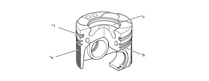
*1 Top Ring Groove (Ni-resist Cast Iron Ring Carrier) - - *a Resin Coating *b Cooling Channel *c Combustion Chamber - - -
-
-
Connecting Rod
-
The connecting rods and caps are made of high-strength material to ensure the proper strength.
-
Knock pins are used at the mating surfaces of the bearing caps of the connecting rod to minimize the shifting of the bearing caps during assembly.
-
Nutless type plastic region tightening bolts are used.
-
The connecting rod bearings are reduced in width to reduce friction.
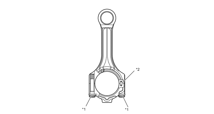
*1 Plastic Region Tightening Bolt *2 Knock Pin
-
-
Crankshaft
-
A crankshaft made of forged steel, which excels in rigidity and wear resistance, is used.
-
The crankshaft has 5 journals and 7 balance weights.
-
All pins and journal fillets are IH (Induction Hardening)-finished to maintain adequate strength.
-
An aluminum bearing is used for the crankshaft bearings.
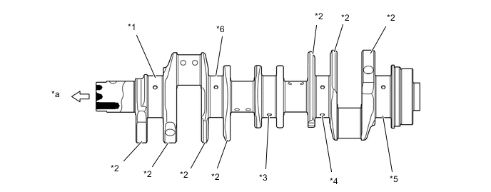
*1 No. 1 Journal *2 Balance Weight *3 No. 3 Journal *4 No. 4 Journal *5 No. 5 Journal *6 No. 2 Journal *a Engine Front - -
-
-
Crankshaft Pulley
-
Three bolts tighten the crankshaft pulley onto the crankshaft to reduce the tightening torque and improve serviceability.
-
An inertial weight is installed via a torsional damper rubber to reduce vibrations.
Figure 2. Models without Viscous Heater
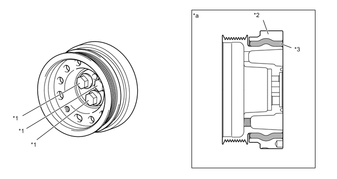
*1 Bolt *2 Inertial Weight *3 Torsional Damper Rubber - - *a Cross Section - -
-
-
Oil Pan
-
The No. 1 oil pan sub-assembly is made of aluminum alloy.
-
The No. 2 oil pan sub-assembly is made of steel.
-
The No. 1 oil pan sub-assembly is secured to the cylinder block and the transmission housing to increase rigidity.
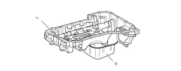
*1 No. 1 Oil Pan Sub-assembly *2 No. 2 Oil Pan Sub-assembly
-
-
Engine Mounting
-
General
-
Two front engine mountings on each side of the engine and one rear engine mounting at the back of the transmission are provided.
-
Electrical hydraulic type engine mountings are used for the front engine mounting. These mountings are operated by the vacuum which is generated by the vacuum pump that is used to control engine mountings.
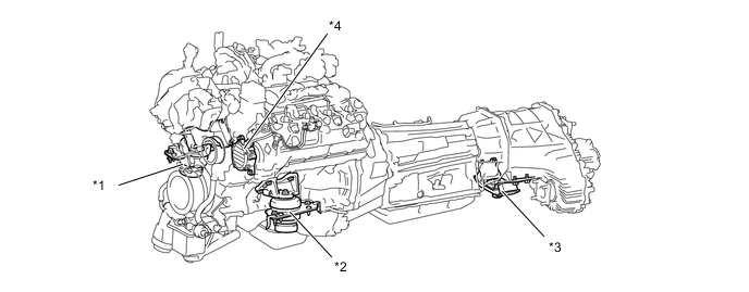
*1 Front Engine Mounting Insulator RH *2 Front Engine Mounting Insulator LH *3 Rear Engine Mounting Insulator *4 Vacuum Pump Assembly
-
-
Vacuum Pump
-
A compact and lightweight vane type vacuum pump with 1 blade is used.
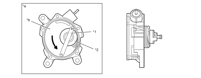
*1 Vane *2 Rotor *a Cross Section *b Pump Chamber Tech Tips
The maintenance interval (replacement) of the vacuum pump is every 200000 km. For details, refer to the Repair Manual.
-
-