3UR-FE ENGINE
-
General
-
A cyclone pre-cleaner is used.
-
The Electronic Throttle Control System-intelligent (ETCS-i) is used to ensure excellent throttle control in all operating ranges.
-
The Acoustic Control Induction System (ACIS) is used to improve the engine performance in all speed ranges.
-
A plastic intake manifold is used.
-
Stainless steel exhaust manifolds and exhaust pipes are used.
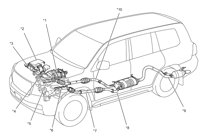
*1 Intake Manifold *2 Air Cleaner *3 Pre-cleaner *4 Throttle Body *5 Exhaust Manifold RH *6 Exhaust Manifold LH *7 Front Exhaust Pipe LH *8 Center Exhaust Pipe *9 Tail Exhaust Pipe *10 Front Exhaust Pipe RH
-
-
Air Cleaner
-
A nonwoven, full-fabric type air cleaner element is used.
-
A cyclone pre-cleaner has been provided in the air cleaner case. This cyclone pre-cleaner has a screw shape (turbinated blade) and gathers large dust particles in a dust cup by swirling the inlet air. The dust cup is removable from the inside of the air cleaner case, so the gathered dust can be disposed of.
-
A rear duct is provided for the air cleaner inlet, thus enhancing anti-dust performance while keeping engine performance.
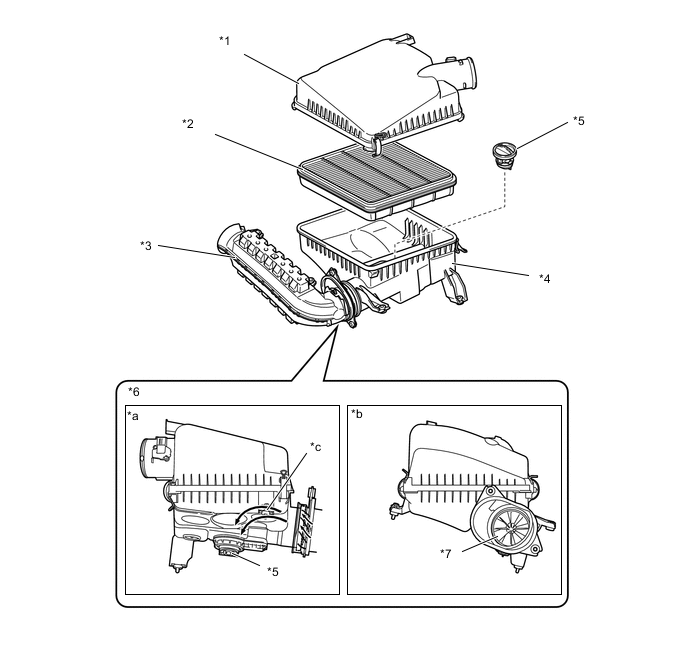
*1 Air Cleaner Cap *2 Air Cleaner Filter Element *3 Air Cleaner Inlet *4 Air Cleaner Case *5 Dust Cup *6 Cyclone Pre-cleaner *7 Turbinated Blade - - *a Rear View *b Side View *c Swirl Air Flow - -
-
-
Throttle Body
-
A throttle body in which the throttle position sensor and the throttle control motor are integrated is used. It achieves excellent throttle valve control.
-
For a throttle control motor, a DC motor with excellent response and minimal power consumption is used. The ECM performs duty cycle control of the direction and the amperage of the current that is supplied to the throttle control motor in order to regulate the throttle valve angle.
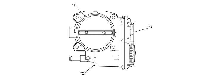
*1 Throttle Valve *2 Throttle Control Motor *3 Throttle Position Sensor Portion - -
-
-
Intake Manifold
-
An intake manifold with a built-in plastic intake air chamber is used for weight reduction.
-
The port diameter and length are optimized to achieve high torque in all driving ranges.
-
The intake manifold contains valves for the Acoustic Control Induction System (ACIS), and the actuator is laser-welded to the intake manifold.
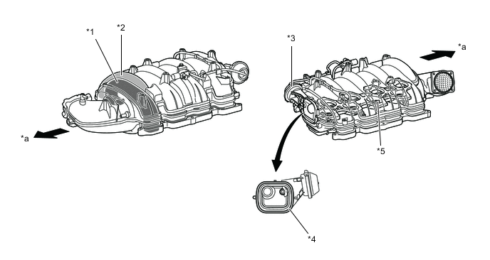
*1 Left Bank Passage *2 Right Bank Passage *3 ACIS Actuator *4 Laser-welding *5 Intake Air Control Valve - - *a Front - - Tech Tips
Laser-welding:In laser-welding, a laser-absorbing material (for the intake manifold) is joined to a laser-transmitting material (for the ACIS actuator). Laser beams are then irradiated from the laser-transmitting side. The beams penetrate the laser-transmitting material to heat and melt the surface of the laser-absorbing material. Then, the heat of the laser-absorbing material melts the laser-transmitting material and causes both materials to become welded.
-
-
Exhaust Manifold
-
A stainless steel exhaust manifold is used for weight reduction and rust resistance.
-
A ceramic type Three-Way Catalytic converter (TWC) is provided in each exhaust manifold for the right bank and the left bank. The exhaust emission performance of the engine is improved as a result of these TWCs.
-
The exhaust manifold heat insulator is made of corrugated aluminum. This ensures rigidity, and at the same time, increases the surface area to improve heat dissipation. Furthermore, a floating construction is used at the tightened area to reduce the transfer of heat and vibration to the heat insulator and improve reliability.
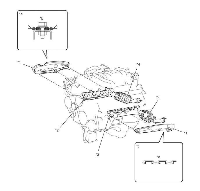
*1 Heat Insulator *2 Exhaust Manifold RH *3 Exhaust Manifold LH *4 TWC *a Heat Insulator Tightened Area Cross Section *b Floating Construction *c Heat Insulator Cross Section *d Corrugated
-
-
Exhaust Pipe
-
General
-
The exhaust pipes are made of stainless steel to reduce their weight and improve rust resistance.
-
A 2-way exhaust control system is provided in the main muffler.
-
A ceramic type TWC is provided in each front exhaust pipe for the right bank and the left bank. As a result, exhaust emission performance of the engine is improved.
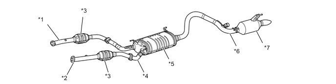
*1 Front Exhaust Pipe RH *2 Front Exhaust Pipe LH *3 TWC *4 Center Exhaust Pipe *5 Main Muffler *6 Tail Exhaust Pipe *7 Sub Muffler - -
-
-
2-way Exhaust Control System
-
General
-
2-way exhaust control system reduces the back pressure by opening and closing a control valve that is enclosed in the main muffler, thus varying the exhaust gas pressure.
-
The control valve opens steplessly in accordance with the operating condition of the engine, thus enabling a quieter operation at lower engine speeds, and reducing back pressure at higher engine speeds.
-
When the exhaust pressure overcomes the spring force of the control valve, the control valve opens steplessly in accordance with the exhaust gas pressure.
-
-
Operation
-
When Control Valve is Closed (Low Engine Speed)
-
Since the pressure in the muffler is low, the control valve is closed. Hence exhaust gas does not pass the bypass passage, and exhaust noise is decreased in the muffler.
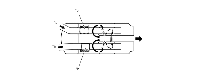
*a Exhaust Gas *b Control Valve Closed -
When Control Valve is Open (Middle to High Engine Speed)
-
The valve opens as the engine speed and the back pressure in the muffler increase. This allows a large volume of exhaust gas to pass the bypass passage, thereby substantially decreasing the back pressure.
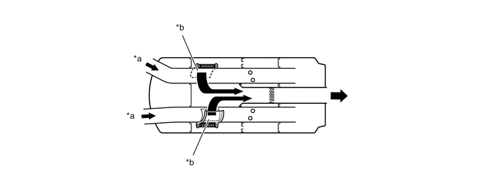
*a Exhaust Gas *b Control Valve Open
-
-
-