3UR-FE ENGINE
-
General
-
The cooling system uses a pressurized forced circulation system with open air type reservoir tank.
-
An water distribution pathway is provided between the left and right banks of the cylinder block.
-
A thermostat with a bypass valve is located on the plastic water inlet to maintain suitable temperature distribution in the cooling system.
-
An aluminum radiator core is used for weight reduction.
-
A 2-stage temperature-controlled coupling fan is used. It rotates at lower speeds when the engine is cold to minimize fan noise.
-
TOYOTA genuine Super Long Life Coolant (SLLC) is used.
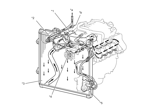
*1 Throttle Body *2 Thermostat *3 Radiator *4 Water Pump *5 Oil Cooler - - *a To Heater Radiator *b From Heater Radiator Figure 1. Water Circuit
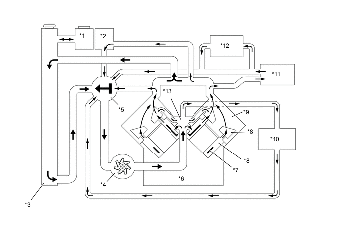
*1 Radiator Reservoir Tank *2 Throttle Body *3 Radiator *4 Water Pump *5 Thermostat *6 Cylinder Block *7 Cylinder Block Water Jacket Spacer *8 Water Jacket *9 Cylinder Head *10 Oil Cooler *11 Heater Radiator *12 ATF Cooler (Warmer) *13 Water Distribution Pathway - - Specifications Engine Coolant Type TOYOTA Genuine Super Long Life Coolant (SLLC) or similar high quality ethylene glycol based non-silicate, non-amine, non-nitrite and non-borate coolant with long-life hybrid organic acid technology (coolant with long-life hybrid organic acid technology is a combination of low phosphates and organic acids.) Do not use plain water alone. Color Pink Maintenance Intervals First Time 160000 km (100000 miles) Subsequent Every 80000 km (50000 miles) Thermostat Opening Temperature 80 - 84°C (176 - 183°F)
-
SLLC is pre-mixed (50% coolant and 50% deionized water). Therefore, no dilution is needed when SLLC in the vehicle is added or replaced.
-
-
-
Water Pump
-
A rust-resistant water pump rotor made of stainless steel is used.
-
The water pump circulates the water to the water distribution pathway located between the left and right banks of the cylinder block.
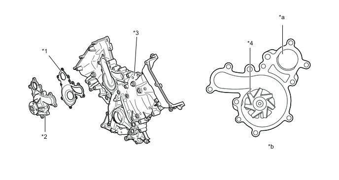
*1 Water Pump Gasket *2 Water Pump *3 Timing Chain Cover *4 Rotor *a From Water Inlet Housing *b View from Back Side
-
-
Water Distribution Pathway
-
The water pump circulates the water and directs it to the water distribution pathway located between the left and right banks. From there, the water is uniformly distributed to each cylinder of the cylinder block, and also directly discharged to the cylinder heads. As a result, the cooling performance of the cylinder heads is assured and reliability is improved.
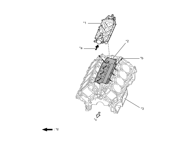
*1 Heat Exchanger Cover *2 Water Distribution Pathway *3 Cylinder Block - - *a From Water Pump *b To Cylinder Head *c Front Side *d Water Flow
-