1GR-FE ENGINE
-
General
-
A compact and lightweight segment conductor type generator that generates high amperage output in a highly efficient manner is provided as standard equipment.
-
This generator has a joined segment conductor system in which multiple segment conductors are welded together to form the stator. Compared to the conventional winding system, the electrical resistance is reduced due to the shape of the segment conductors, and their arrangement helps to make the generator compact.
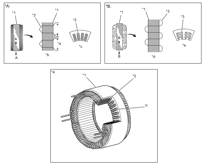
*A Segment Conductor Type Generator *B Conventional Type Generator *1 Stator *2 Segment Conductor *3 Conductor Wire *4 Stator of Segment Conductor Type Generator *a Joined *b Joined Segment Conductor System *c A - A CrossSection *d Winding System *e B - B CrossSection *f Cross Section Specifications Type SE0 Rated Voltage 12 V Rated Output 100 A Figure 1. Wring Diagram
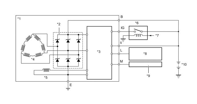
*1 Generator *2 Rectifier *3 Regulator *4 Stator *5 Rotor *6 IG1 Relay *7 Main Body ECU *8 Combination Meter
-
Discharge Warning Light
*9 ECM *10 Battery -
-
A one-way clutch is set into the generator pulley.
-
Operation of the one-way clutch cancels generator pulley inertia and helps to prevent slipping of the V-ribbed belt. This provides a low tension V-ribbed belt that achieves reduced friction.
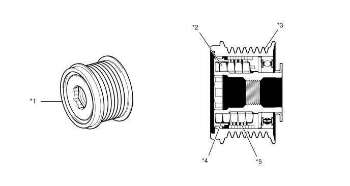
*1 Generator Pulley *2 Coil Spring *3 Pulley *4 Shaft *5 One-way Clutch - -
-