1GR-FE ENGINE
-
General
-
A fuel cut control is used to stop the fuel pump when SRS airbags deploy in a frontal or side collision.
-
The fuel pressure pulsation damper assembly and fuel pressure regulator assembly are surface-treated to be compatible with alcohol fuel, resulting in improving the corrosion resistance.
-
Compact 12-hole type fuel injectors are used to improve the atomization of fuel.
-
The fuel injector assembly is shaped to form a long nozzle. This shortens the distance from the fuel injector to the intake valve, which prevents the fuel from adhering to the intake port walls and reduces exhaust emissions.
-
Quick connectors are used to connect the fuel lines for ease of serviceability.
-
The dual fuel tank which is comprised of a fuel tank and a fuel sub tank is provided.*
-
*: Models with dual fuel tank
-
-
A multi-layer plastic fuel tank is used. (The fuel sub tank however is made of steel.)
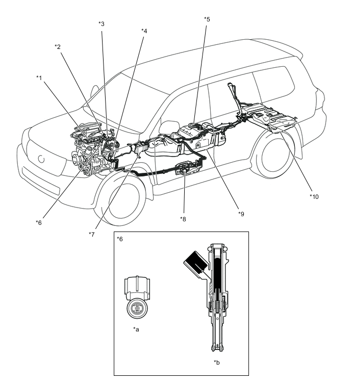
*1 Fuel Delivery Pipe Sub-assembly *2 Fuel Pressure Regulator Assembly *3 Fuel Pressure Pulsation Damper Assembly *4 Quick Connector *5 Fuel Suction with Pump and Gauge Tube Assembly
-
Fuel Pump
-
Fuel Sender Gauge
-
Jet Pump
*6 Fuel Injector Assembly *7 Canister *8 Fuel Filter *9 Fuel Tank *10 Fuel Sub Tank *a Bottom Side View *b Fuel Injector Assembly Cross Section -
-
-
Fuel Delivery Pipe
-
The fuel delivery pipe is made of plastic to reduce weight.
-
The right and left fuel delivery pipes are connected by a nylon tube.
-
The pulsation damper is sealed with an O-ring and secured with a holder.
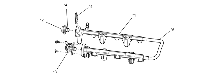
*1 Fuel Delivery Pipe Sub-assembly *2 Fuel Pressure Pulsation Damper Assembly *3 Fuel Pressure Regulator Assembly *4 O-ring *5 Holder *6 Nylon Tube
-
-
Fuel Tank
-
General
-
The multi-layer plastic fuel tank consists of 6 layers of 4 types of materials, and one of those is a recyclable material to address environmental concerns.
-
A jet pump, which automatically transfers fuel from the fuel sub tank to the fuel tank, is provided in the fuel tank on models with a dual fuel tank.
Figure 1. Cross Section of Fuel Tank

*1 Adhesive *2 High Density Polyethylene *3 Recyclable Material *4 Ethylene Vinyl Alcohol Copolymer *a Interior of Fuel Tank *b Exterior of Fuel Tank Tech Tips
A drain mark has been provided at the lowest position of the fuel tank. When dismantling (scraping) the vehicle, drain fuel by drilling holes at the drain mark.
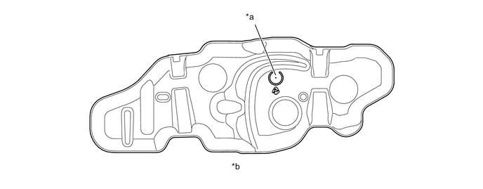
*a Drain Mark *b View from Bottom Side
-
-
Construction of Dual Fuel Tank
-
General
-
A jet pump is provided in the fuel tank in order to automatically transfer fuel from the fuel sub tank to the fuel tank.
-
A fuel filler pipe which has a unified structure directly below the fuel inlet but which branches into two at a midway point in used. Therefore, the driver can refuel without the need to distinguish the fuel tank from the fuel sub tank.
Figure 2. System Diagram
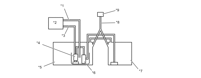
*1 Return Tube *2 Engine *3 Main Tube *4 Fuel Pump *5 Fuel Tank *6 Jet Pump *7 Fuel Sub Tank *8 Fuel Filler Pipe *9 Fuel Inlet - -
-
-
Fuel Inlet
-
There is only one fuel filler pipe directly below the fuel inlet, which branches into two pipes at a midway point.

*1 Fuel Supply Nozzle *2 Fuel Inlet *3 Fuel Filler Pipe - - *a To Sub Fuel Tank *b To Main Fuel Tank
-
-
Operation
-
The fuel from the fuel pump actuates the jet pump in the fuel tank, in order to draw fuel from the fuel sub tank to the fuel tank.
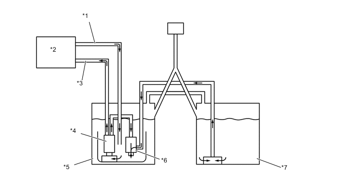
*1 Return Tube *2 Engine *3 Main Tube *4 Fuel Pump *5 Fuel Tank *6 Jet Pump *7 Fuel Sub Tank - - -
The fuel from the fuel pump passes through the orifice in the jet pump and returns to the fuel tank. Because the flow speed of the fuel from the fuel pump increases as it passes through the orifice, a vacuum is created near the exit of the orifice. This vacuum causes the fuel to be drawn from the fuel sub tank to the fuel tank.
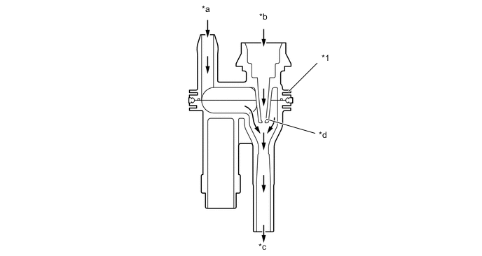
*1 Jet Pump - - *a From Fuel Sub Tank *b From Fuel Pump *c To Fuel Tank *d Orifice
-
-
-