1GR-FE ENGINE
-
Cylinder Head Cover
-
Lightweight yet high-strength aluminum cylinder head cover sub-assemblies are used.
-
An oil filler housing has been provided on the cylinder head cover sub-assembly LH to improve the serviceability when filling the engine oil.
-
An oil delivery pipe is installed inside each cylinder head cover sub-assemblie. This ensures lubrication to the sliding parts of the valve rocker arm sub-assemblies, achieving reliability.
-
The cylinder head cover gasket and a gasket to seal the ignition coil circumference have been integrated to reduce the number of parts.
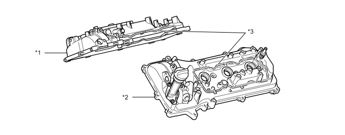
*1 Cylinder Head Cover Sub-assembly RH *2 Cylinder Head Cover Sub-assembly LH *3 Oil Delivery Pipe Sub-assembly - -
-
-
Cylinder Head Gasket
-
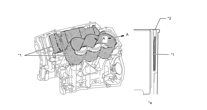
A steel-laminate type cylinder head gasket is used.
-
A shim has been added around the cylinder bore to increase the sealing surface, thus improving the sealing performance and durability
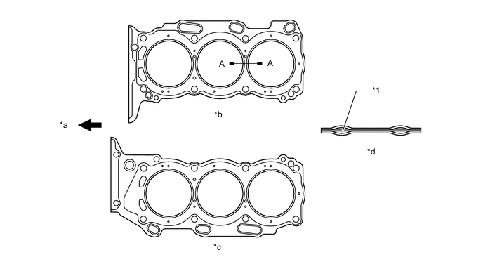
*1 Shim - - *a Front *b Right Bank *c Left Bank *d A - A Cross Section
-
-
Cylinder Head Sub-assembly
-
The cylinder head sub-assembly structure has been simplified by separating the camshaft housing (cam journal portion) from the cylinder head.
-
The cylinder head, which is made of aluminum, contains a pentroof-type combustion chamber. The spark plug has been located in the center of the combustion chamber in order to improve the engine's anti-knocking performance.
-
The intake ports are on the inside and the exhaust ports on the outside of the left and right banks respectively.
-
Upright intake ports are used to improve the intake efficiency.
-
A taper squish combustion chamber is used to improve anti-knocking performance and intake efficiency. In addition, engine performance and fuel economy have been improved.
-
By fitting the fuel injector assembly so that its nozzle end juts into the intake port, the intake port cross sectional area has become smooth, enhancing the efficiency of air intake. Furthermore, the distance between the injector nozzle end and intake valve has been shortened. As a result, the amount of fuel that adheres to the intake port has been reduced, increasing the fuel economy as well as reducing the exhaust emissions.
-
The siamese type intake port is used to reduce the overall surface area of the intake port walls. This prevents the fuel from adhering onto the intake port walls, thus reducing HC exhaust emissions.
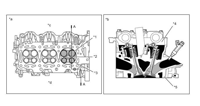
*1 Intake Valve *2 Spark Plug Hole *3 Exhaust Valve *4 Camshaft Housing *5 Cylinder Head - - *a Bottom Side View *b A - A Cross Section *c Intake Side *d Exhaust Side Tech Tips
Siamese Type Intake Port and Independent Type Intake Port
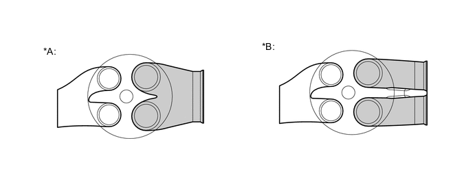
*A Siamese Type *B Independent Type -
The cylinder head bolts have been positioned below the camshaft journal in the front of the right bank, and the holes for placing the bolts have been provided above the camshaft journal. Thus, the front end of the right bank has been shortened, resulting in a shorter overall length of the engine.
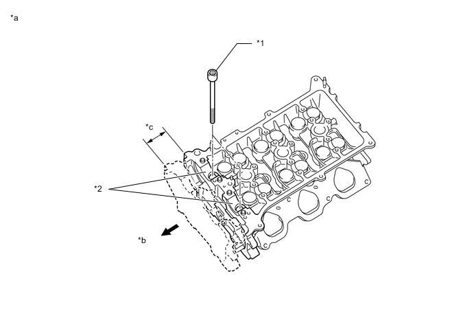
*1 Cylinder Head Bolt *2 Camshaft Journal *a Right Bank Cylinder Head *b Front *c Shortened - -
-
-
Cylinder Block Sub-assembly
-
General
-
The cylinder block is made of aluminum alloy.
-
The cylinder block has a bank angle of 60°, a bank offset of 36.6 mm (1.441 in.) and a bore pitch of 105.5 mm (4.15 in.), resulting in a compact block in its length and width even for its displacement.
-
Installation bosses of the two knock sensors are located on the inner side of left and right banks.
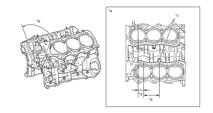
*a View from Top Side *b 60° *c Knock Sensor Boss *d 36.6 mm (1.441 in.) *e 105.5 mm (4.15 in.) - - -
Water passages have been provided between the cylinder bores. By allowing the engine coolant to flow between the cylinder bores, this construction enables the temperature of the cylinder walls to be kept uniform.
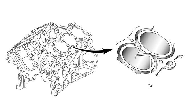
*a Water Passage - - -
A compact block has been achieved by producing the thin cast-iron liners and cylinder block as a unit. Do not bore the block with this liner.
-
-
Spiny-type Liner
-
The liners are the spiny-type, which have been manufactured so that their casting exterior forms a large irregular surface in order to enhance the adhesion between the liners and the aluminum cylinder block. The enhanced adhesion helps improve heat dissipation, resulting in a lower overall temperature and heat deformation of the cylinder bores.
-
The shape of the cross-hatching of the liner surface has been optimized to improve oil retention performance, resulting in reduced friction.
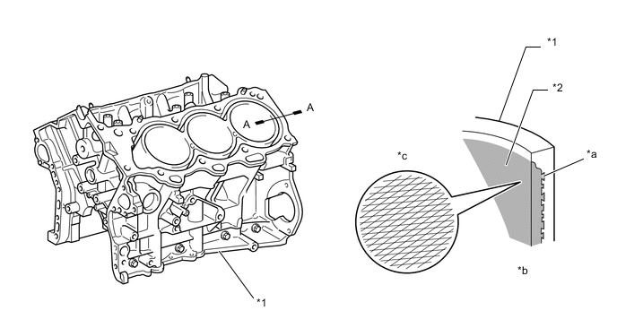
*1 Cylinder Block *2 Liner *a Irregularly Shaped Outer Casting Surface of Liner *b A - A Cross Section *c Enlarged View of Cross-hatching - -
-
-
Cylinder Block Water Jacket Spacer
-
Cylinder block water jacket spacers have been added to the water jacket.
-
The cylinder block water jacket spacer prevents water flow in the middle and below the water jacket and draws coolant above the cylinder bore, to ensure uniform temperature distribution. As a result, the viscosity of the engine oil that acts as a lubricant between the bore walls and the pistons can be lowered, thus reducing friction.
*1 Cylinder Block Water Jacket Spacer *2 Water Jacket *a A - A Cross Section - -
-
-
-
Piston
-
The pistons are made of aluminum alloy.
-
The piston shape has been optimized for a high compression ratio.
-
The piston head portion uses a taper squish shape to accomplish fuel combustion efficiency.
-
In order to reduce weight, cast holes have been provided on the bottom of the piston head near the pin bosses as shown in the illustration below.
-
The piston skirt has been coated with resin to reduce the friction loss.
-
The groove of the top ring has been coated with anodic oxide to improve wear resistance and rust resistance.
-
This piston is common to all cylinders. Therefore, the pistons are not shaped especially for the right or the left bank. As a result, serviceability has been improved.
-
The outer surface of the No. 2 compression ring has been plated with chrome in order to be compatible with gasoline/ethanol mixed fuel.
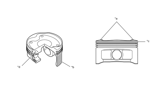
*a Taper Squish Shape *b Resin Coating *c Anodic Oxide Coating *d Weight Reduction Area
-
-
Connecting Rod and Connecting Rod Bearing
-
Connecting rods that have been forged for high strength are used for weight reduction.
-
Knock pins are used at the mating surfaces of the bearing caps of the connecting rod to minimize the shifting of the bearing caps during assembly.
-
Plastic region tightening bolts are used.
-
An aluminum bearing is used for the connecting rod bearings.
-
The lining surface of the connecting rod bearing has been micro-grooved to realize an optimal amount of oil clearance. As a result, cold-engine cranking performance has been improved and engine vibrations have been reduced.
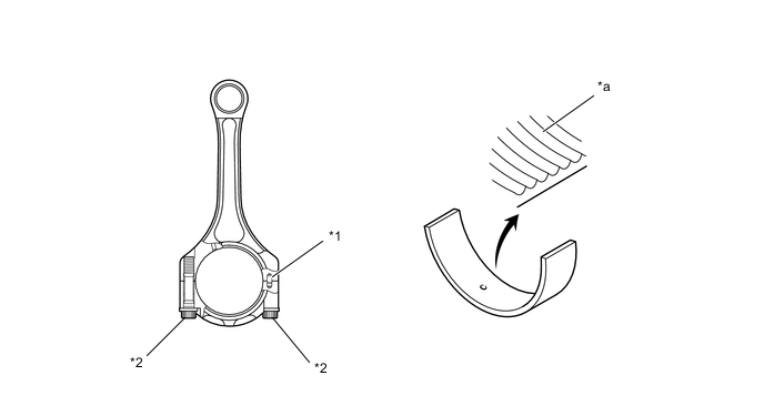
*1 Knock Pin *2 Plastic Region Tightening Bolt *a Micro-Grooved - -
-
-
Crankshaft
-
A crankshaft made of steel, which excels in rigidity and wear resistance, is used.
-
A 5 balance weight crankshaft is used for weight reduction, and the installation locations of the balance weights have been optimized to reduce vibration and noise.
-
All pin and journal fillets are roll-finished to maintain adequate strength.
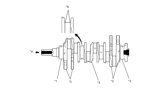
*1 No. 1 Journal *2 No. 4 Journal *3 Balance Weight - - *a Front *b Roll-Finished
-
-
Crankshaft Bearing and Crankshaft Bearing Cap
-
The crankshaft bearings are made of aluminum alloy.
-
Similar to the connecting rod bearings, the lining surface of the crankshaft bearings has been micro-grooved to realize an optimal amount of oil clearance. As a result, cold-engine cranking performance has been improved and engine vibrations have been reduced.
-
The upper crankshaft bearing has an oil groove around its inside circumference.
-
The crankshaft bearing caps are tightened using 4 plastic-region tightening bolts for each journal. In addition, each cap is tightened laterally to improve its reliability.
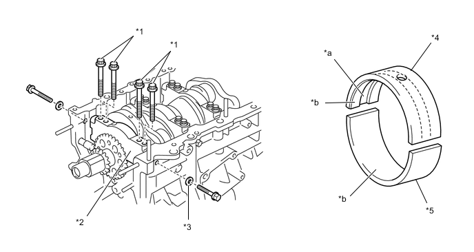
*1 Plastic Region Tightening Bolt *2 Crankshaft Bearing Cap *3 Seal Washer *4 Upper Crankshaft Bearing *5 Lower Crankshaft Bearing - - *a Oil Grooved *b Micro-Grooved
-
-
Crankshaft Pulley
-
The rigidity of the torsional damper rubber has been optimized to reduce noise.

*1 Torsional Damper Rubber - -
-
-
Oil Pan
-
The No. 1 oil pan sub-assembly is made of aluminum alloy.
-
The No. 2 oil pan sub-assembly is made of steel.
-
An oil passage has been integrated in the No. 1 oil pan sub-assembly to simplify the construction of the oil strainer.
-
The No. 1 oil pan sub-assembly is secured to the cylinder block and the torque converter housing and is increasing rigidity.

*1 No. 1 Oil Pan Sub-assembly *2 No. 2 Oil Pan Sub-assembly *a Oil Passage *b A - A Cross Section
-