1GR-FE ENGINE
-
General
-
The intake camshafts are driven by the crankshaft via the No.1 chain. The intake camshaft of the respective bank drives the exhaust camshafts via the No.2 chain.
-
A Dual Variable Valve Timing-intelligent (VVT-i) system is used. As a result, the valve timing has been optimized, achieving lower fuel consumption, higher engine performance and lower exhaust emissions.
-
A valve rocker arm sub-assemblies with built-in needle bearings are used. This reduces the friction that occurs between the cams and the valve rocker arm sub-assemblies that push the valves down, thus improving fuel economy.
-
Valve lash adjuster assemblies, which maintain a constant zero valve clearance through the use of oil pressure and spring force, are used.
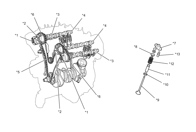
*1 Camshaft Timing Gear Assembly (Exhaust) *2 Camshaft Timing Gear Assembly (Intake) *3 Exhaust Camshaft *4 Intake Camshaft *5 No. 1 Chain *6 No. 2 Chain *7 Valve Rocker Arm Sub-assembly *8 Valve Spring Retainer *9 Valve *10 Valve Spring Seat *11 Valve Guide Bush *12 Compression Spring *13 Valve Lash Adjuster Assembly - -
-
-
Camshaft
-
The camshafts are made of a cast iron alloy.
-
A camshaft timing gear assembly has been added at the front end of the exhaust camshafts to vary the timing of the exhaust valves.
-
Oil passages are provided on the intake and exhaust camshafts in order to supply engine oil to the VVT-i system.
-
Together with the use of the valve rocker arm sub-assemblies, the cam profile has been optimized. This results in increased valve lift when the valve begins to open and as it finishes closing, helping to achieve enhanced output performance.
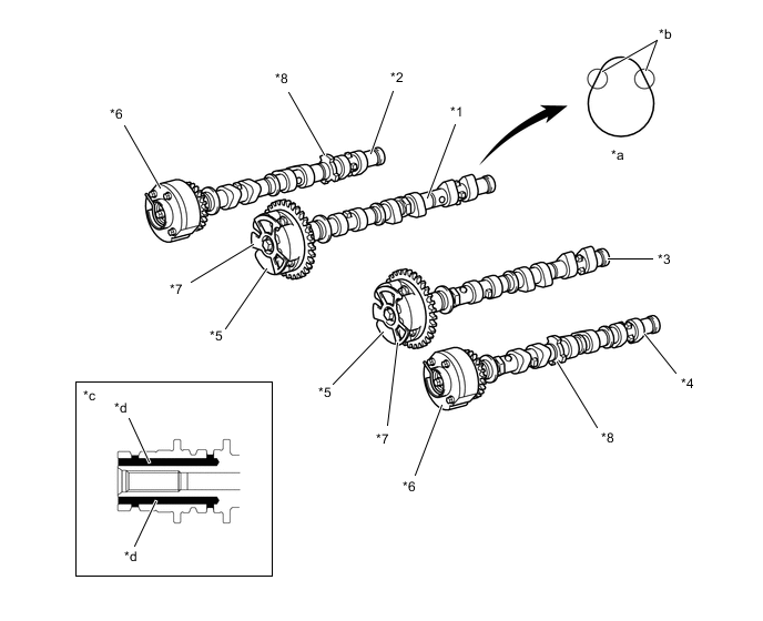
*1 No. 1 Camshaft (Intake) *2 No. 2 Camshaft (Exhaust) *3 No. 3 Camshaft (Intake) *4 No. 4 Camshaft (Exhaust) *5 Camshaft Timing Gear Assembly (Intake) *6 Camshaft Timing Gear Assembly (Exhaust) *7 Timing Rotor for VVT Sensor (Intake) *8 Timing Rotor for VVT Sensor (Exhaust) *a Cam with Indented R *b Indented R Portion of Cam (Profile) *c Cross Section of End of Intake Camshaft *d Oil Passage
-
-
Timing Chain and Chain Tensioner
-
Both the No. 1 and No. 2 chains use roller chains with a pitch of 9.525mm (0.375 in.).
-
The timing chain is lubricated by timing chain oil jet.
-
The No. 1 chain uses one timing chain tensioner and each of the No. 2 chains for the right and left banks uses one timing chain tensioner.
-
The chain tensioners use a spring and oil pressure to maintain proper chain tension at all times. They suppress noise generated by the timing chains.
-
The No. 1 chain tensioner is the ratchet type with a non-return mechanism.
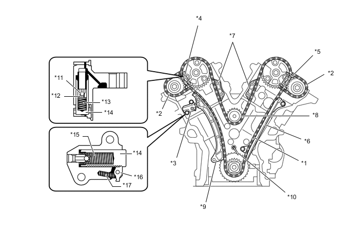
*1 No. 1 Chain *2 No. 2 Chain *3 No. 1 Chain Tensioner *4 No. 2 Chain Tensioner *5 No. 3 Chain Tensioner *6 No. 1 Chain Vibration Damper *7 No. 2 Chain Vibration Damper *8 No. 1 Idle Gear *9 Chain Tensioner Slipper *10 Timing Chain Oil Jet *11 Ball *12 Ball Spring *13 Main Spring *14 Plunger *15 Spring *16 Cam *17 Cam Spring - -
-
-
Timing Chain Cover
-
The timing chain cover has an integrated construction consisting of the cooling system (water pump and water passage) and the lubrication system (oil pump and oil passage). Thus, the number of parts has been reduced to reduce weight.
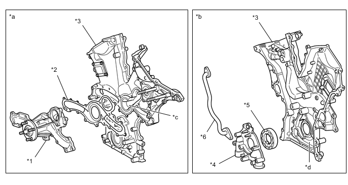
*1 Water Pump Assembly *2 Water Pump Gasket *3 Timing Chain Cover *4 Oil Pump Housing *5 Oil Pump Rotor *6 Oil Passage *a Front Side View *b Back Side View *c Water Pump Swirl Chamber *d Oil Pump Chamber
-
-
Valve Lash Adjuster Assembly
-
The valve lash adjuster assembly, which is located at the fulcrum of the valve rocker arm sub-assembly, consists primarily of a plunger, plunger spring, check ball and check ball spring.
-
The engine oil that is supplied by the cylinder head and the built-in spring actuate the valve lash adjuster assembly. The oil pressure and the spring force that act on the plunger push the valve rocker arm sub-assembly against the cam, in order to adjust the valve clearance that is created during the opening and closing of the valve. As a result, engine noise is reduced.
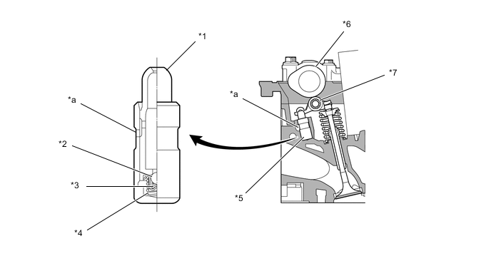
*1 Plunger *2 Check Ball *3 Check Ball Spring *4 Plunger Spring *5 Valve Lash Adjuster Assembly *6 Cam *7 Valve Rocker Arm Sub-assembly - - *a Oil Passage - - Tech Tips
Valve clearance adjustment is not necessary because valve lash adjuster assemblies are used.
-