BODY STRUCTURE
-
FUNCTION
-
Impact Absorbing Structure for Frontal Collision
-
A structure that ensures collision energy absorption efficiency, dissipates impact, and minimizes cabin deformation during a frontal collision has been achieved.
-
Front impact energy entering from the upper side member is transmitted efficiently to the center pillar through the beltline (*a).
-
The load box reduces the time needed to transfer the impact energy to the underbody at the moment of collision (*b).
-
Front impact energy entering from the front side member is distributed efficiently amongst the under body structure (*c).
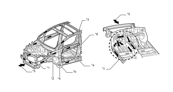
Text in Illustration *1 Front Side Member *2 Upper Side Member *3 Beltline *4 Load Box *5 Front Impact Energy *6 Center Pillar
-
-
Dash panel insulator pads are used on the lower section of the dash panel, helping reduce injuries to the legs.
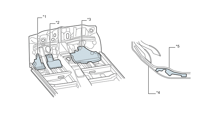
Text in Illustration *1 No. 2 Dash Panel Insulator Pad *2 No. 1 Dash Panel Insulator Pad *3 No. 3 Dash Panel Insulator Pad *4 Dash Panel *5 Floor Carpet - -
-
-
Impact Absorbing Structure for Side Collision
-
A structure that ensures collision energy absorption efficiency, dissipates impact, and minimizes cabin deformation during a side collision has been achieved.
-
The center body pillar reinforcement is optimally placed to suppress cabin intrusion at the time of a side collision.
-
Rocker panel reinforcements are provided at the sides of the front floor cross member and center floor cross member in order to transmit the load to the cross members.
-
The roof panel reinforcement is used in order to convey the load more efficiently.
-
The side impact protect beams are optimally placed to suppress cabin intrusion at the time of a side collision.
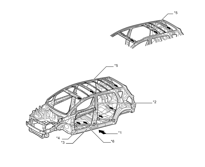
Text in Illustration *1 Side Impact Energy *2 Center Body Pillar Reinforcement *3 Rocker Panel Reinforcement *4 Floor Cross Member *5 Roof Panel Reinforcement *6 Side Impact Protect Beam -
-
On the models without Supplemental Restraint System (SRS) curtain shield airbag assembly, a head impact protection structure is used. With this type of construction, if the occupant's head hits against the roof side rail and pillar in reaction to a collision, the inner panel of the roof side rail and pillar collapses to help reduce the impact.
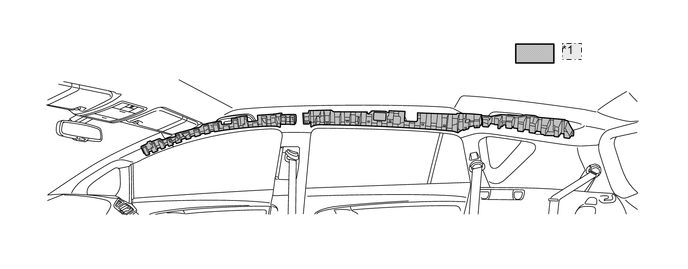
*1 EA rib -
Door trim lower pads are provided in the door trims to help dampen the impact applied from the sides of the vehicle to the occupants.
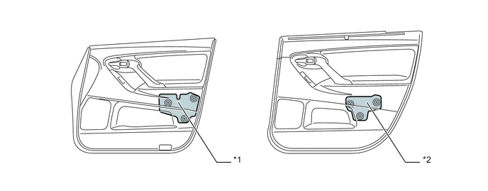
Text in Illustration *1 Front Door Trim Lower Pad *2 Rear Door Trim Lower Pad -
The following structures have been built into the rear cabin in order to lessen the impact applied to passengers in the event of a side collision:
-
In order to strengthen the rear door and reduce impact force, a beltline inner reinforcement and an EA pad have been provided.
-
Additional aluminum and resin hybrid stiffeners convey the load to the seat rod more efficiently and minimize deformation of the rear door.
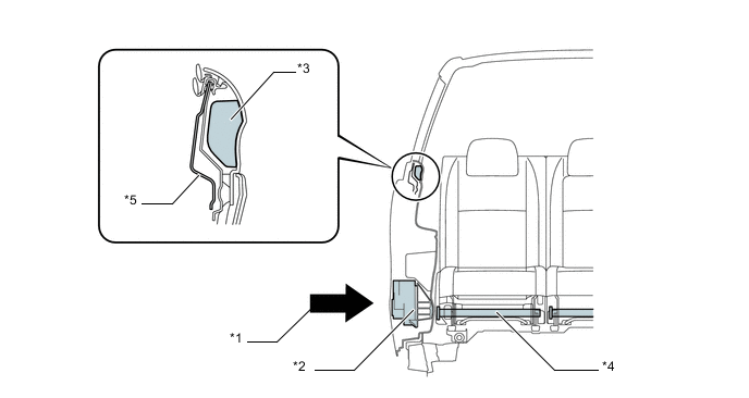
Text in Illustration *1 Side Impact Energy *2 Side Impact Pad (Aluminum and Resin Hybrid Stiffener) *3 EA Pad *4 Seat Rod *5 Beltline Inner Reinforcement - - -
-
-
Lessening Pedestrian Head Injury
-
A hood lock is located behind the radiator support. By ensuring a distance between the hood panel and the hood lock, collision energy caused by a pedestrian colliding with the hood panel is reduced in order to ensure pedestrian protection performance.
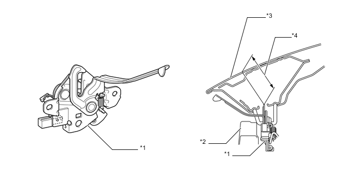
Text in Illustration *1 Hood Lock *2 Radiator Support *3 Hood Panel *4 Deformation Zone -
A collision stopper has been located to allow the hood hinge arm to rotate further downwards than the fully closed position without any interference. This enables the hood hinge arm to rotate downwards when a pedestrian collides with the hood panel, thus reducing collision energy and ensuring pedestrian protection performance.
Text in Illustration *1 Collision Stopper *2 Hood Hinge Bracket *3 Hood Hinge Arm - - -
An apron fender side extension and a front apron to cowl side member plate are used in the joint portion of the front fender. Thus, a certain deformation stroke in the event of a head form collision has been ensured, reducing the impact.
Text in Illustration *1 Apron Fender Side Extension *2 Front Apron to Cowl Side Member Plate *3 Head Form *4 Deformation Zone -
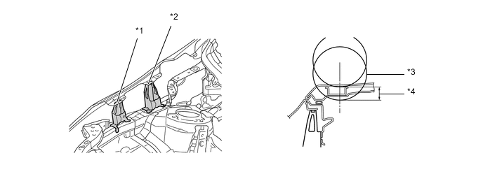
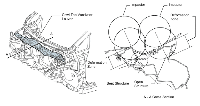
The cowl louver uses a bent structure. Collision energy is absorbed using an enhanced folding mode. The cowl area also has an open structure. In the event of a collision with a pedestrian, this structure helps lessen the impact inflicted by the cowl to the head of the pedestrian.
-
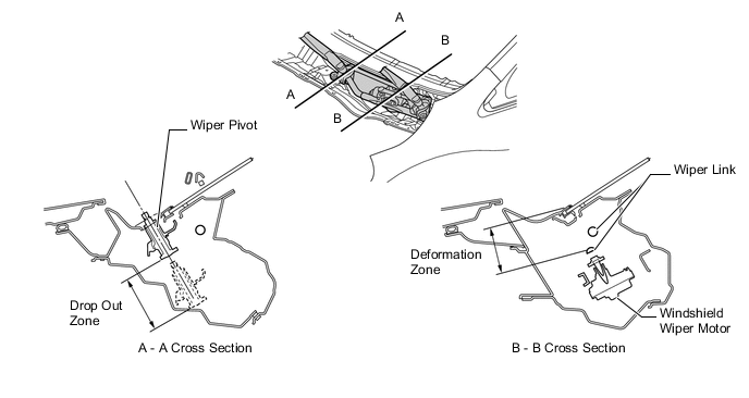
By locating the windshield wiper motor on the lower part of the wiper link, and by using a body structure that causes the wiper pivot to drop out, the stroke to reduce impact energy from the top of the cowl louver is ensured.
-
A front bumper energy absorber and a front bumper absorber lower are provided in front of the front bumper reinforcement and below the radiator support lower. This structure helps lessen the impact applied to the legs of the pedestrians.
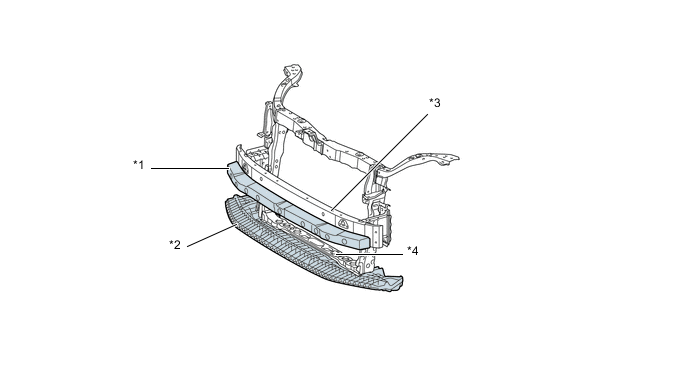
Text in Illustration *1 Front Bumper Energy Absorber *2 Front Lower Bumper Absorber *3 Front Bumper Reinforcement *4 Lower Radiator Support
-
-
Aerodynamics
-
A front spoiler side protector is provided at the lower end of the front bumper cover, thus reducing the Cd level.
Tech Tips
The Cd level refers to the air resistance coefficient. Cd stands for Coefficient of drag (or Constant drag). The lower the level is, the lesser the air resistance is. This improves fuel efficiency.
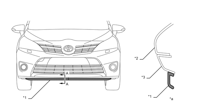
Text in Illustration *1 Front Spoiler Side Protector *2 Front Bumper Cover *3 Front Spoiler Cover - - *a A - A Cross Section - - -
By providing a vertical bead on the upper face of the front fender liner and by providing a rectifying effect on the air flow inside the wheel house, driveability has been improved. Also, a large front wheel opening extension pad with a slit construction is used, actualizing the aerodynamics and braking cooling performance.
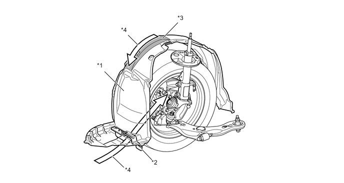
Text in Illustration *1 Front Fender Liner *2 Front Wheel Opening Extension Pad *3 Bead *4 Air Flow -
Various types of airflow routing parts that control airflow are provided under the floor, and an undercover is provided to make the under-floor area flat in order to ensure excellent aerodynamic performance.
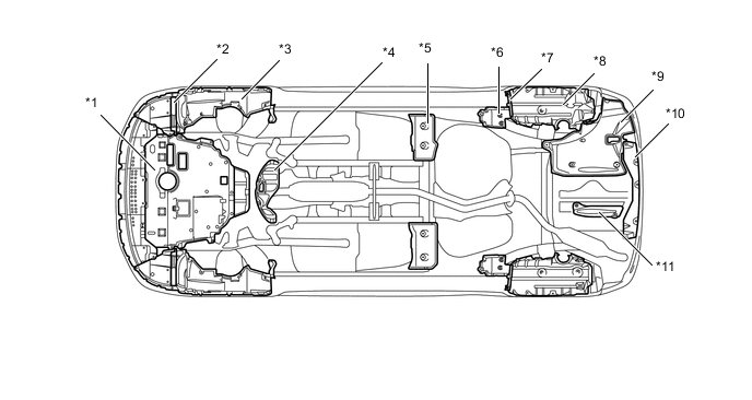
Text in Illustration *1 No. 1 Engine Undercover *2 Front Wheel Opening Extension Pad *3 Front Fender Liner *4 No. 2 Engine Undercover *5 Front Floor Cover Center *6 Rear Floor Side Member Cover *7 Rear Wheel House Plate Front *8 Rear Wheel House Liner *9 No. 2 Floor Undercover *10 No. 1 Floor Undercover *11 Air Guide Plate - - -
On the back surface of the rear floor, wing shaped vertical fins are set in order to improve both aerodynamics and vehicle stability.
Text in Illustration *1 Vertical Fin - - -
A rear spoiler is provided, giving a rectifying effect and allowing superior aerodynamic performance.
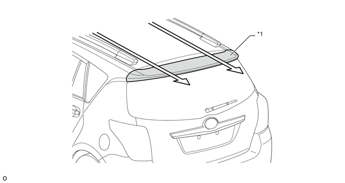
Text in Illustration *1 Rear Spoiler - - 
Air Flow - -
-
-
-
CONSTRUCTION
-
High-strength Sheet Steel
-
High-strength sheet steel and ultra high-strength sheet steel are used in order to achieve excellent body rigidity and a lightweight body.
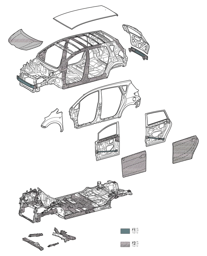
*1 Ultra high-strength sheet steel *2 High-strength sheet steel
-
-
Stability and Controllability
-
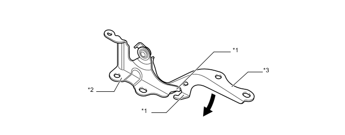
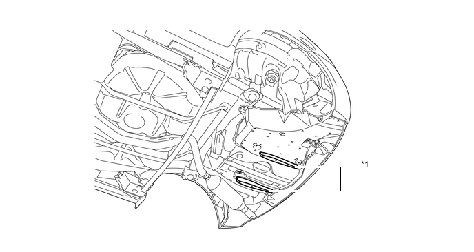
Braces have been provided at the bottom of the front suspension member to help ensure the rigidity of the front suspension member in the longitudinal direction.
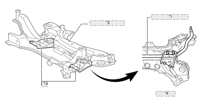
*1 Front Stabilizer Bar *2 Front Suspension Crossmember *3 Brace *4 Bottom View
-
-
High Rigidity Body
-
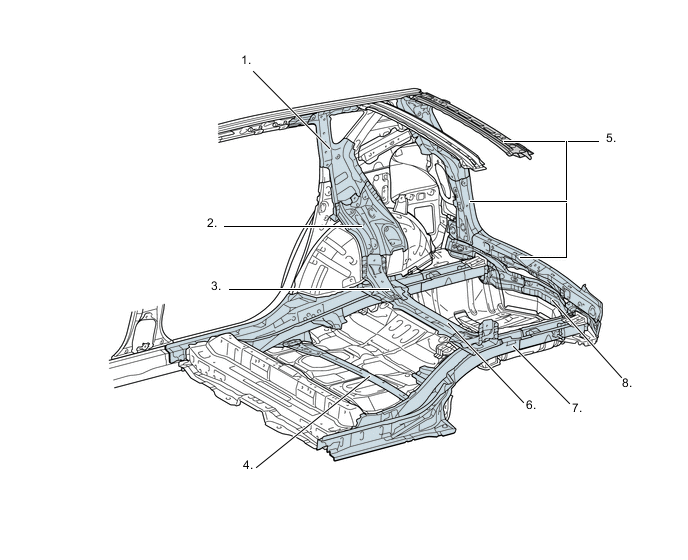
Efficient reinforcement around the back door opening and rear suspension support point improves the rigidity of the body torsion and rear suspension point.
-
The shape of quarter pillar reinforcement has been straightened.
-
By connecting the wheelhouse and wheelhouse gusset, a continuous closed cross section has been achieved.
-
A rear floor cross member gusset is provided.
-
Rear suspension brace contributes to body rigidity.
-
By connecting the lower back panel, quarter pillar and rear header, a continuous closed cross section has been achieved.
-
A rear No. 2 lower cross member is provided to ensure rigidity.
-
Cross section is closed with lower back reinforcement.
-
The rear floor side member is reinforced.
-
-
Many spot welding points are provided in the periphery of the door opening and back door opening, thus ensuring stability while maneuvering (yaw response, steering response and rear grip feeling) by enhancing the strength of the connection between the panels.
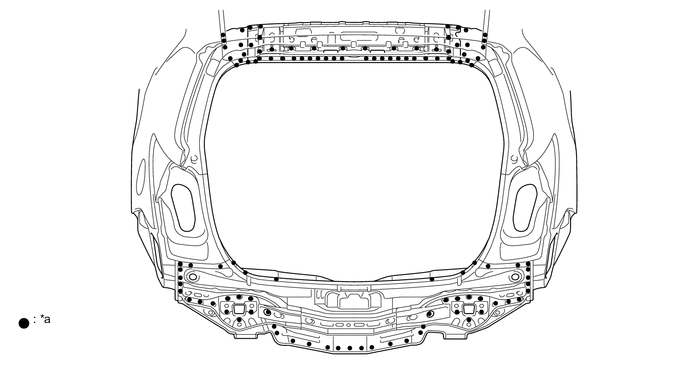
Text in Illustration (Back Door Opening) *a Spot Welding Point - - 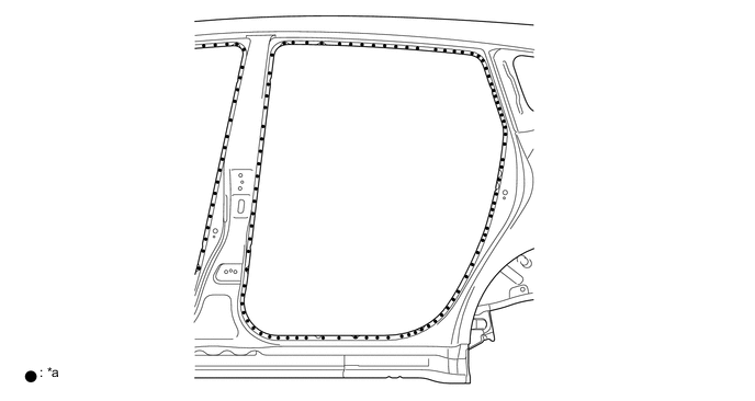
Text in Illustration (Rear Door Opening) *a Spot Welding Point - -
-
-
Anti-corrosion Sheet Steel
-
Anti-corrosion sheet steel is used as in the following illustration:
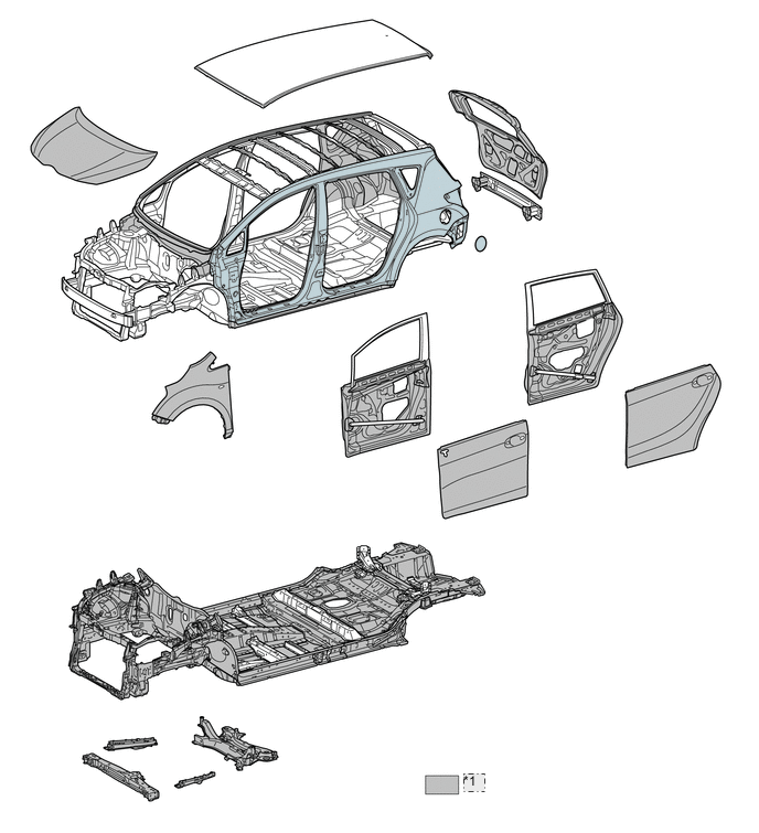
*1 Anti-corrosion sheet steel -
Wax is applied to front end of the hood panel, the edge of the each of the door lower portions, door hinge and the fuel filler lid hinge to improve rust-resistant performance. Sealer is applied to hemmed portions of the door panels and back door panel.
-
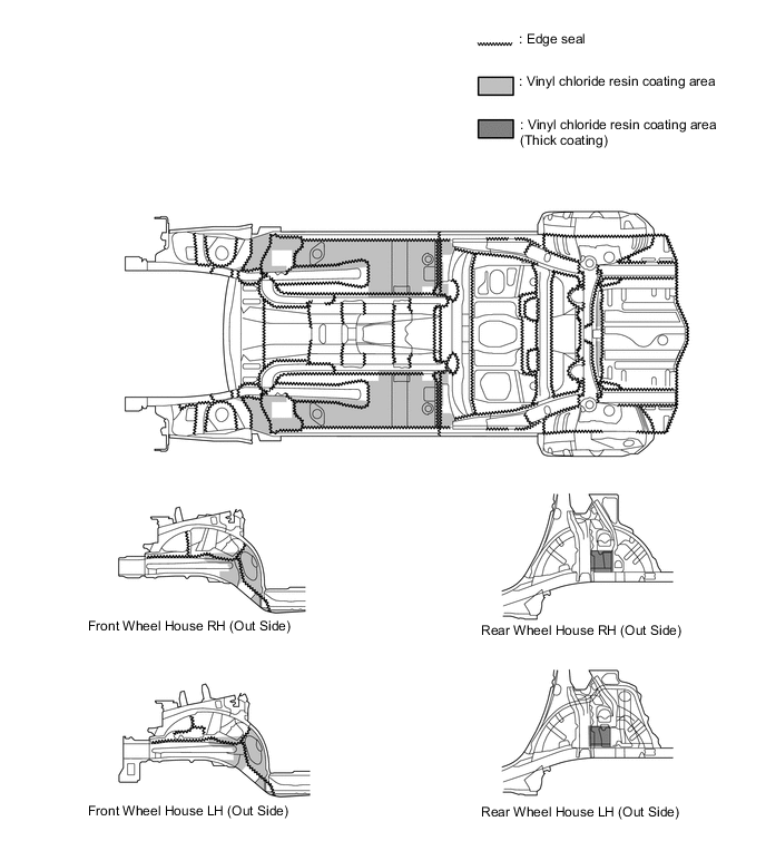
Vinyl chloride resin is applied to under side of the body, inside the wheel housing and other parts that are susceptible to stone chipping damage, thus improving the rust-resistant performance of these areas.
-
-
Anti-chipping Application
-
To protect the paint from chipping while the vehicle is being driven, anti-chipping paint is applied to the rockers and the front end of the hood panel.
-
A quarter panel protector and a rear door panel protector are available as an option on the quarter panel on the back of the rear door to protect the paint surface from icy snow or gravel and to achieve a high level of rust resistance.
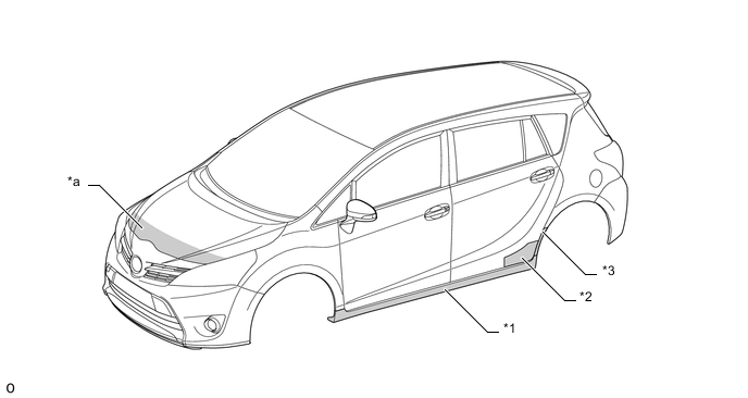
Text in Illustration *1 Body Rocker Panel Molding Assembly *2 Rear Door Panel Protector *3 Quarter Panel Protector - - *a Soft Chipping Primer - -
-
-
Sound Absorbing and Vibration Damping Materials
-
A hood insulator is provided on the rear of the hood panel. This achieves excellent sound insulation performance.
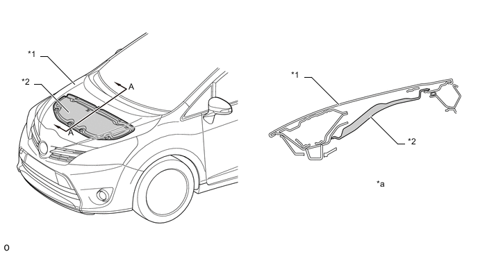
Text in Illustration *1 Hood Panel *2 Hood Insulator *a A - A Cross Section - - -
A dash panel insulator outer is provided. This reduces the amount of engine noise leaking into and out of the cabin.
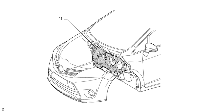
Text in Illustration *1 Dash Panel Insulator Outer - - -
No. 2 dash panel insulator outer is provided at the front of the cowl. This reduces the noise coming from the engine compartment and achieves superior quietness.
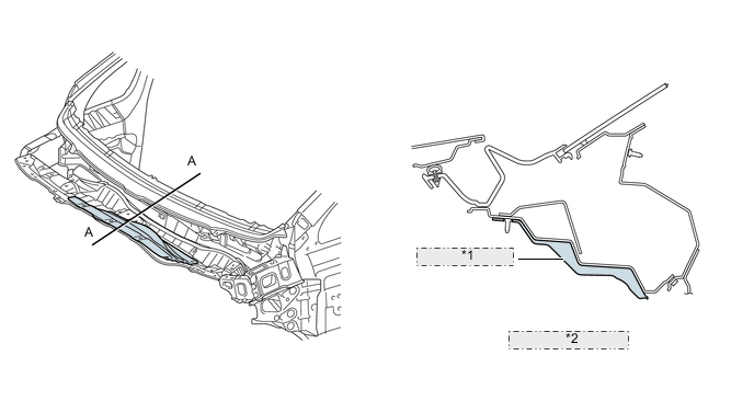
*1 No. 2 Dash Panel Insulator *2 A - A Cross Section -
A dash panel insulator assembly is provided. This insulates and absorbs the engine noise to reduce the amount of engine noise leaking into the cabin.
-
The following features have been given to achieve a superior sound absorption and insulation performance.
-
Extension of the center and lower areas (B in the illustration).
-
Extension of the side areas (C in the illustration).
-
Hole size reduction (D in the illustration).
-
Material addition on top of the air conditioning intake duct (E in the illustration).
-
Foam flap addition over the body panel (F in the illustration).
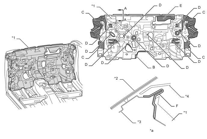
Text in Illustration *1 Dash Panel Insulator Assembly *2 Windshield Glass *3 Cowl Top Panel Inner *4 Instrument Panel Sub-assembly Upper *a A - A Cross Section - - -
-
To reduce the amount of road noise, engine noise, and droning sound that enters the cabin, the floor panel is coated with a floor silencer.
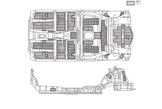
*1 Floor silencer -
A sound absorbing pad is provided on the upper surface of the front fender liner. This absorbs road noise and achieves superior quietness.
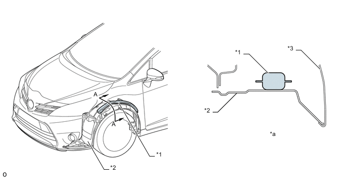
Text in Illustration *1 Absorbing Pad *2 Front Fender Liner *3 Fender Panel - - *a A - A Cross Section - - -
A front fender side panel protector is provided between the front pillar and the fender panel. This prevents road noise from entering the cabin, and achieves superior quietness.
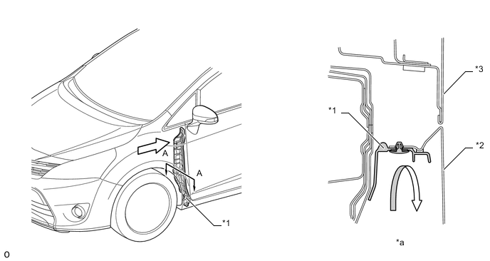
Text in Illustration *1 Front Fender Side Panel Protector *2 Fender Panel *3 Front Door Panel - - *a A - A Cross Section - - Noise - - -
Nonwoven cloth type rear wheel house liner and rocker panel moulding is provided. This reduces chipping noises caused by sand being thrown up by the tire from entering the cabin, and achieves superior quietness.
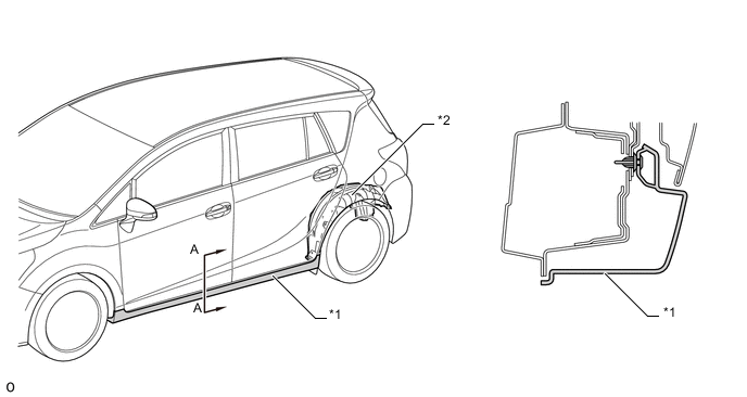
Text in Illustration *1 Body Rocker Panel Molding Assembly *2 Rear Wheel House Liner *a A - A Cross Section - - -
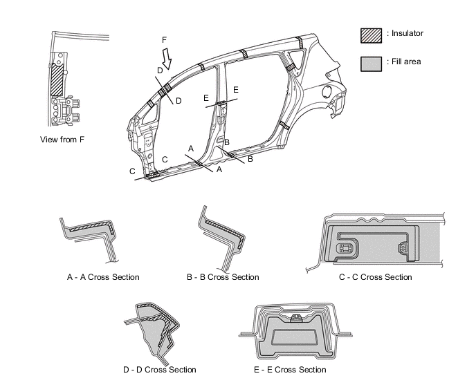
A foam type sound insulation material is used in the body frame profile, thus dampening the various noises which intrude from the outside of the vehicle to the inside of the cabin.
-
The rear bumper reinforcement and the rear bumper arm use a bolt-on structure to enable efficient repair or replacement work.
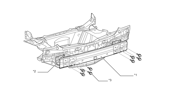
Text in Illustration *1 Rear Bumper Reinforcement *2 Rear Bumper Arm *3 Bolt - -
-
-