ECD SYSTEM
-
FUNCTION OF MAIN COMPONENTS
-
The main components of the 1WW engine control system are as follows:
Component Quantity Function ECM 1 The ECM performs overall control of the engine control system to suit the operating conditions of the engine in accordance with the signals from the sensors. Atmospheric Pressure Sensor (Built into ECM) 1 This sensor, which is built into the ECM, uses semiconductors to detect the atmospheric pressure. Atmospheric Temperature Sensor (Built into ECM) 1 This sensor, which is built into the ECM, uses a thermistor to detect the atmospheric temperature. Intake Mass Air Flow Meter Sub-assembly Mass Air Flow Meter 1 This sensor uses a built-in hot-wire to directly detect the intake air mass. Intake Air Temperature Sensor (Built into Intake Mass Air Flow Meter Sub-assembly) 1 This sensor detects the intake air temperature by means of an internal thermistor. Intake Air Temperature Sensor (for Compressed Intake Air) 1 This sensor detects the intake air temperature past the turbocharger and intercooler. Diesel Throttle Body Assembly Throttle Control Motor 1 This motor regulates the opening of the diesel throttle valve in accordance with the signals from the ECM. Throttle Position Sensor 1 This sensor detects the diesel throttle valve opening angle. Accelerator Pedal Position Sensor 1 This sensor detects the amount of pedal effort applied to the accelerator pedal. Fuel Temperature Sensor 1 This sensor detects the fuel temperature in the fuel line before the supply pump assembly by means of an internal thermistor. Fuel Pressure Sensor 1 This sensor uses built-in semiconductors to detect the internal pressure of the common-rail assembly. Crankshaft Position Sensor 1 This sensor detects the engine speed and performs the cylinder identification. Camshaft Position Sensor 1 This sensor performs the cylinder identification. Turbo Pressure Sensor Assembly 1 This sensor detects the intake manifold pressure. Engine Coolant Temperature Sensor 1 This sensor detects the engine coolant temperature by means of an internal thermistor. Air Fuel Ratio Sensor 2 This sensor detects the oxygen concentration in the exhaust gas. Nozzle Vane Position Sensor 1 This sensor detects the nozzle vane position. Swirl Control Valve Position Sensor 1 This sensor detects the diesel swirl control valve opening angle. Actuator (for Turbocharger) 1 This actuator regulates the opening of the nozzle vane in accordance with the signals from the ECM. Actuator (for Swirl Control) 1 This actuator regulates the opening of the swirl control valve in accordance with the signals from the ECM. Glow Plug Controller 1 The glow plug controller controls the length of time for which the current is applied to the glow plug assemblies in accordance with the signals from the ECM. Fuel Quantity Control Valve 1 The valve position is controlled by the signals from the ECM, and a fuel volume that suits the valve position is drawn into the pumping portion (plunger portion). Pressure Discharge Valve 1 The pressure discharge valve regulates the fuel pressure. Injector Assembly 4 The injector injects the fuel to the combustion chamber in accordance with the signals from the ECM. Fuel Pump Assembly 1 The fuel pump assembly feeds fuel to the supply pump assembly. Glow Plug Assembly 4 The glow plug assembly heats the combustion chamber.
-
-
SYSTEM CONTROL
-
The engine control system of the 1WW engine has the following systems:
System Outline Fuel Injection Control Based on the signals received from the sensors, the ECM determines the fuel injection volume and fuel injection timing in accordance with the engine condition. Fuel Pressure Control Based on the signals received from the fuel pressure sensor, the ECM controls fuel pressure using the fuel quantity control valve and pressure discharge valve in accordance with engine operating conditions. For details of the fuel quantity control valve operation, see the 1WW Fuel section. Fuel Pump Control Fuel pump operation is controlled by signals from the ECM in order to feed fuel to the supply pump. Glow Plug Control
-
The ECM sends signals to the glow plug controller in accordance with engine conditions. Based on the signals, the glow plug controller controls the length of time for which the current is applied to the glow plug assemblies in each cylinder.
-
Detects individual disconnections of circuit wires and short circuits by the use of the glow plug controller.
Diesel Throttle Control
-
Controls the diesel throttle valve opening angle in accordance with the engine condition.
-
Fully closes the diesel throttle valve in order to reduce vibration when the engine is stopped.
Fuel Heater Control Based on the signals received from the sensors, the ECM controls the fuel heater.*3 Based on the signals received from the sensors, the ECM controls the fuel heater via the fuel heater relay.*4 Swirl Control Based on the signals received from the sensors, the ECM controls the actuator (for swirl control), in order to open and close the valve. Turbocharger Control Based on the signals received from the sensors, the ECM controls the actuator in accordance with the engine condition. Cooling Fan Control Cooling fan operation is controlled by signals from the ECM based on the engine coolant temperature, air conditioning condition*2, engine speed and vehicle speed. Starter Control*1 Once the engine switch is pushed, this control continues to operate the starter until the engine is started. Air Conditioning Cut-off Control*2 This control turns the air conditioning compressor on or off in accordance with the engine condition to maintain driveability. Engine Immobiliser Prohibits fuel injection if an attempt is made to start the engine with an invalid key. Oil Maintenance Management System
-
The oil maintenance information message is shown on the multi-information display according to the vehicle condition to inform the driver.
-
Remaining oil maintenance mileage is shown on the multi-information display to inform the driver.
Brake Override System The driving torque is restricted when both the accelerator and brake pedals are depressed. (For the activation conditions and inspection method, refer to the Repair Manual.) Diagnosis When the ECM detects a malfunction, the ECM diagnoses and memorizes the failed section. Fail-safe When the ECM detects a malfunction, the ECM stops or controls the engine in accordance with the data already stored in the memory. *1: Models with entry and start system
*2: Models with air conditioning system
*3: Models without fuel heater relay
*4: Models with fuel heater relay
-
-
-
FUNCTION
-
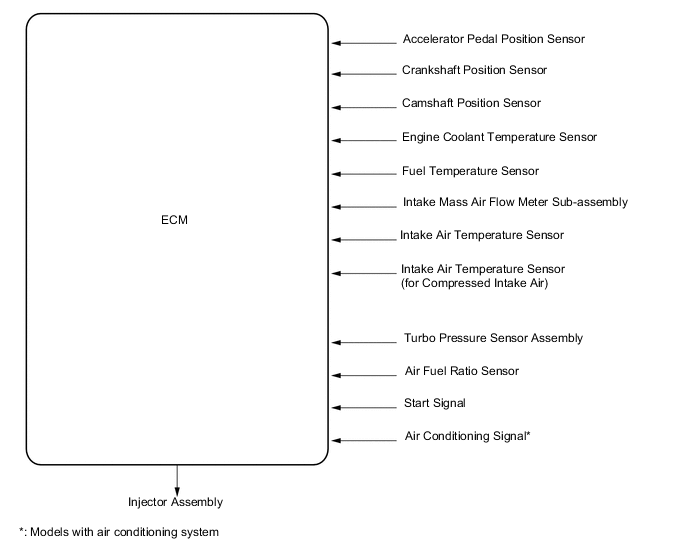
Fuel Injection Control
-
Based on information from various sensors, the ECM determines the injection timing and injection volume according to the engine condition, operates the fuel injectors and controls the fuel injection.
-
The types of fuel injection are as follows:
Fuel Injection Type Purpose Pre-injection Reduces combustion noise by gradually starting fuel combustion for the main injection. Main Injection Optimizes combustion by using optimal fuel injection. Post-injection
-
Activates the oxidation catalyst.
-
Regenerates the Diesel Particulate Filter (DPF) catalyst.
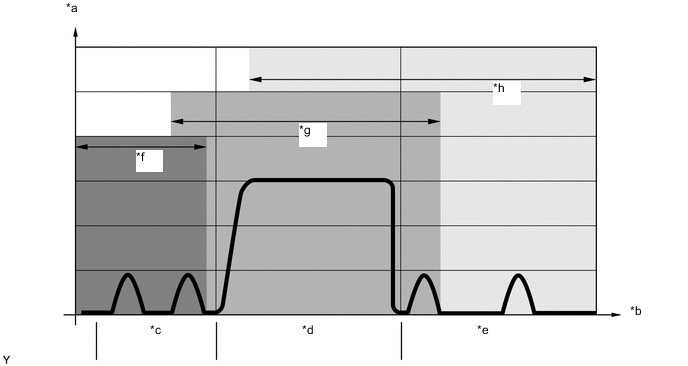
Text in Illustration *a Nozzle Needle Stroke (mm) *b Time (ms) *c Pre-injection *d Main Injection *e Post-injection *f Acoustic Optimization *g Combustion Optimization *h Exhaust Re-treatment Tech Tips
When replacing the following parts, it is necessary to reset the learned values of the ECM. For details of the reset procedure, refer to the Repair Manual.
-
Intake Mass Air Flow Meter Sub-assembly
-
Injector Assembly
-
Fuel Pressure Sensor
-
-
-
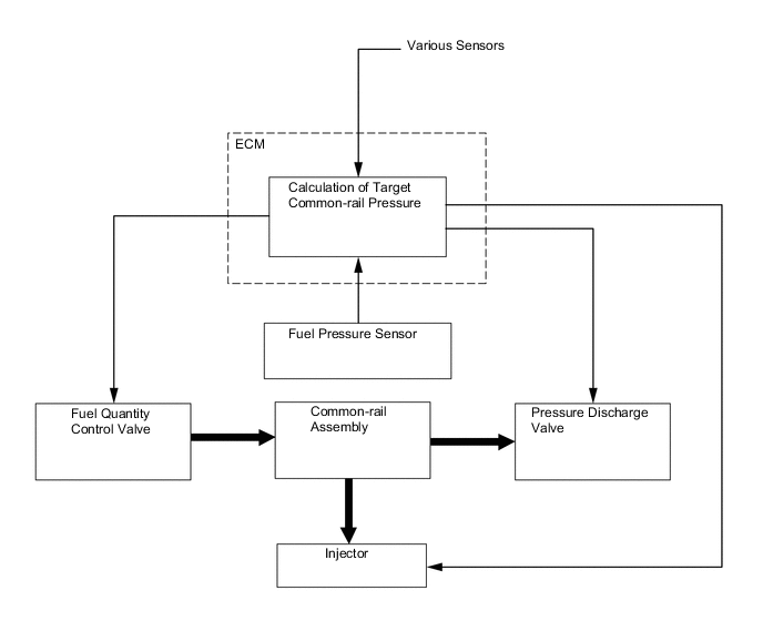
Fuel Pressure Control
-
The ECM calculates the target injection pressure based on the signals from the various sensors. To control fuel pressure, signals sent to the fuel quantity control valve of the supply pump assembly regulate the fuel flow volume, and signals sent to the pressure discharge valve of the common-rail regulate the discharge volume, so that the pressure detected by the fuel pressure sensor matches the target injection pressure.
-
-
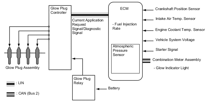
Glow Plug Control
-
The ECM sends a signal to the glow plug controller, and the glow plug controller independently controls the length of time for which the current is applied to the glow plug assemblies in each cylinder in accordance with engine conditions. By independently and precisely controlling the temperature inside each cylinder, low emissions are achieved.
-
-
Diesel Throttle Control
-
Diesel throttle control has following functions:
-
A function that closes the diesel throttle valve to reduce vibration and noise when the engine is being stopped.
-
A function that regulates the volume of intake air to maintain the exhaust gas temperature required to regenerate the Diesel Particulate Filter (DPF) catalyst.
-
A function that prevents the engine speed from increasing excessively when combustion materials other than those introduced during normal fuel injection have gotten into the cylinder.*
Tech Tips
*: For example, if engine oil flows from the turbocharger sub-assembly to the cylinder due to damage to the bearing.
-
-
-
Fuel Heater Control
-
When the fuel temperature is lower than the predetermined temperature, the ECM turns the fuel heater on to heat the fuel.*1
-
When the fuel temperature is lower than the predetermined temperature, the ECM turns the fuel heater on via the fuel heater relay to heat the fuel.*2
-
*1: Models without fuel heater relay
-
*2: Models with fuel heater relay
-
-
-
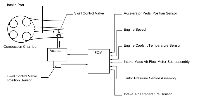
Swirl Control
-
The ECM controls the swirl control valve position to improve torque in the low engine speed range and to optimize exhaust emissions.
-
-
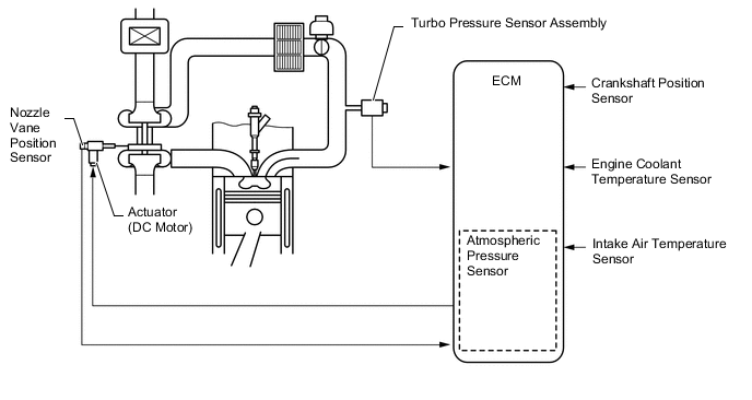
Turbocharger Control
-
The ECM controls the nozzle vane position in order to obtain a calculated target turbo pressure appropriate for the engine operating conditions.
-
-
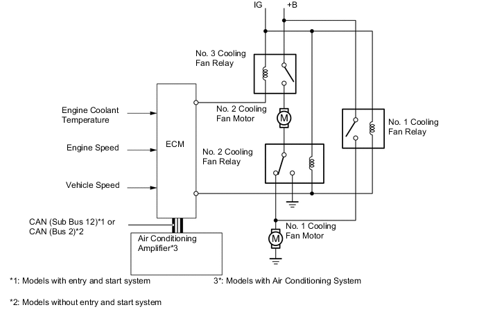
Cooling Fan Control
-
Cooling fan operation is controlled to achieve an optimal fan speed in accordance with the engine coolant temperature, vehicle speed, engine speed and air conditioning operating conditions*.
-
*: Models with air conditioning system
-
-
-
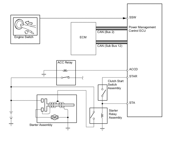
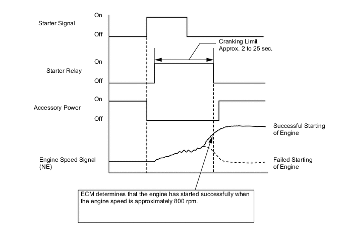
Starter Control (Models with Entry and Start System)
-
Depressing the clutch pedal and pressing the engine switch once will operate the starter continuously until the engine has started completely. Operability and starting operation have thereby been improved.
-
If the power management control ECU and ECM detect a start signal, the ECM will monitor the engine speed signal (NE) and send a starter activation request signal to the power management control ECU using CAN communication until the ECM determines that the engine has started completely. The power management control ECU activates the starter based on a signal from the ECM.
-
-
Oil Maintenance Management System
-
The oil maintenance management system has following functions:
-
Engine Oil Maintenance Reminder Display
-
This function determines the deterioration conditions of the engine oil and displays the oil maintenance information message on the multi-information display to inform the driver when the engine oil must be changed.
-
Remaining Oil Maintenance Mileage Display
-
This function displays the remaining mileage until the next engine oil replacement is required on the multi-information display to inform the driver.
-
-
-
-
CONSTRUCTION
-
Intake Mass Air Flow Meter Sub-assembly
-
This engine uses a hot-film type mass air flow meter designed for direct electrical measurement of the intake mass air flow.
-
The specialized passage forms a complex shape (labyrinth) to detect only the actual intake air mass. As a result, despite the back-flow, pulsation and pressure of the intake air mass, the mass air flow meter can detect the actual intake air mass.
-
This intake mass air flow meter sub-assembly has a built-in intake air temperature sensor.
Text in Illustration *1 Intake Mass Air Flow Meter Sub-assembly *2 Intake Air Temperature Sensor (Temperature Sensing Element) *3 Sensor Measuring Cell - - *a Intake Air Flow *b Partial Measurement Flow Inlet *c Cross-section *d Labyrinth *e Partial Measurement Flow Outlet - -
-
-
Intake Air Temperature Sensor (for Compressed Intake Air)
-
The intake air temperature past the turbocharger and intercooler is detected by the thermistor. This value is used as a substitute value for calculating the intake air mass value. In this way, the value of intake mass air flow meter sub-assembly is checked for plausibility. If the intake mass air flow meter sub-assembly fails, the substitute value is used.
Text in Illustration *1 Intake Air Temperature Sensor - -
-
-
Throttle Position Sensor
-
A non-contact type throttle position sensor, which uses a Hall IC, is mounted on the diesel throttle body assembly.
-
The Hall IC is surrounded by a magnetic yoke. The Hall IC converts the changes that occur in the magnetic flux into electrical signals, and outputs them in the form of throttle valve position signals to the ECM.
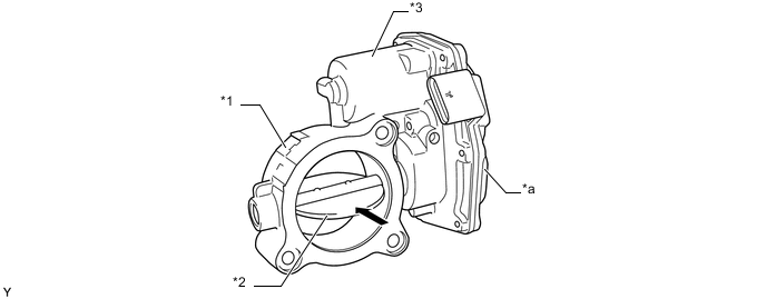
Text in Illustration *1 Diesel Throttle Body Assembly *2 Diesel Throttle Valve *3 Throttle Control Motor - - *a Throttle Position Sensor Portion - - 
Intake Air - -
-
-
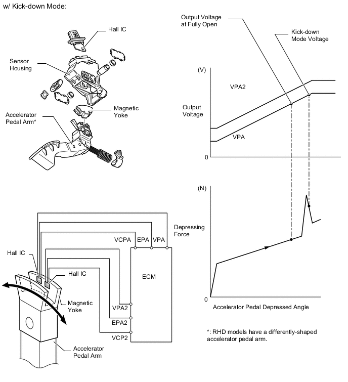
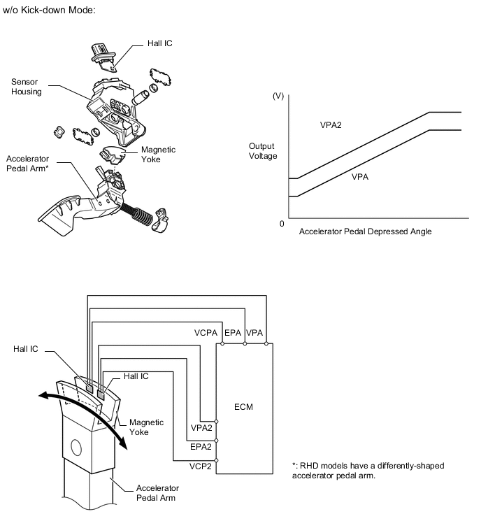
Accelerator Pedal Position Sensor
-
The non-contact type accelerator pedal position sensor uses a Hall IC.
-
The magnetic yoke mounted at the base of the accelerator pedal arm moves around the Hall IC in accordance with the amount of effort applied to the accelerator pedal. The Hall IC converts the changes in the magnetic flux that occur into electrical signals, and outputs them in the form of accelerator pedal effort to the ECM.
-
This accelerator pedal position sensor includes 2 Hall ICs and circuits for the main and sub signals. The sensor converts the accelerator pedal depressed angles into electric signals with 2 differing characteristics and outputs them to the ECM.
-
On the models with kick-down mode, when the depressing force applied to the accelerator pedal is greater than a predetermined amount, the ECM detects a "kick-down mode" from the VPA signal provided by the accelerator pedal position sensor.
-
-
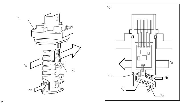
Fuel Pressure Sensor
-
The fuel pressure sensor, which is mounted on the common-rail assembly, outputs a signal that represents the fuel pressure in the common-rail assembly to the ECM in order to constantly regulate the fuel at an optimal pressure.
-
The fuel pressure sensor consists of a semiconductor which utilizes the characteristics of a silicon chip that changes its electrical resistance when pressure is applied to it.

Text in Illustration *1 Fuel Pressure Sensor - - *a Cross-section *b Detection Portion Tech Tips
When the fuel pressure sensor malfunctions, the ECM stores data about the malfunction. Also, the ECM regulates the fuel pressure using the default value.
-
-
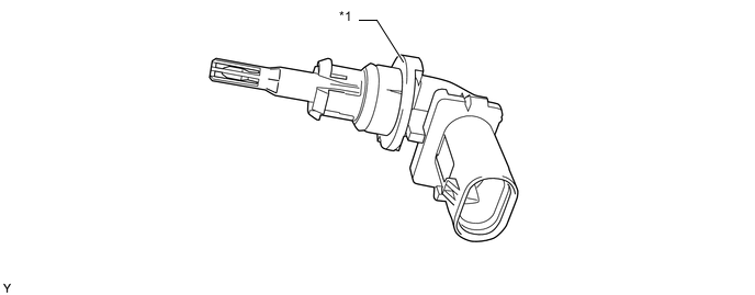
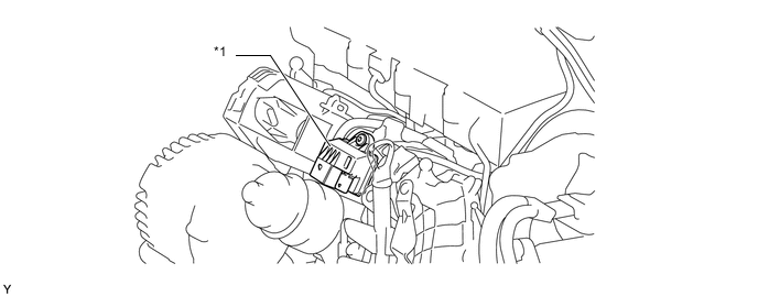
Fuel Temperature Sensor
-
The fuel temperature sensor is located on the low-pressure side before the supply pump assembly.
-
The fuel temperature sensor consists of a precision thermistor made of semiconductor material which is integrated in a housing.
-
The fuel temperature sensor detects the fuel temperature shortly before the supply pump assembly.
Text in Illustration *1 Fuel Temperature Sensor - -
-
-
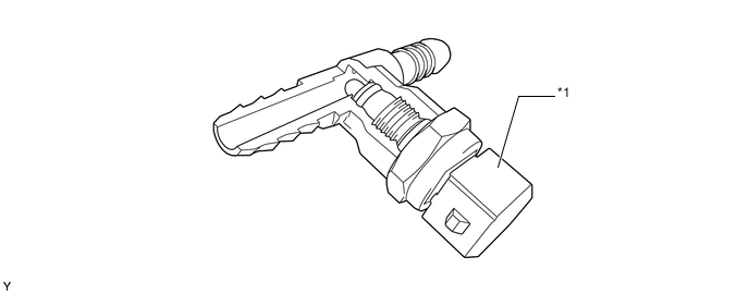
Crankshaft Position Sensor
-
A Hall IC type crankshaft position sensor is used.
-
The multi-pole sensor wheel has 58 magnetic pole pairs and a reference point. The reference point is a magnetic pole pair that is two times longer than the other magnetic pole pairs. TDC is detected using this reference point.
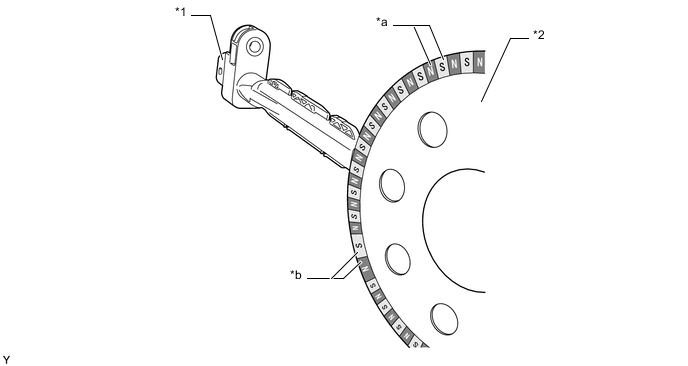
Text in Illustration *1 Crankshaft Position Sensor *2 Multi-pole Sensor Wheel *a Magnetic Pole Pair *b Reference Point -
The transition from a high to a low phase is signaled by a change in the magnetic field. The difference between 2 changes of the magnetic field is 6° crankshaft angle.
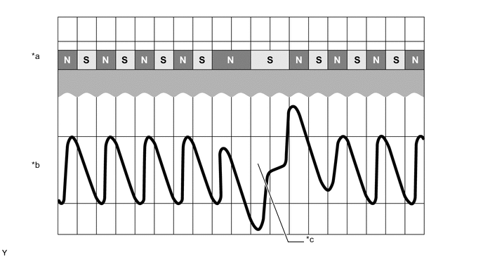
Text in Illustration *a Multi-pole Sensor Wheel *b Signal Shape (Calculated Internally) *c Reference Signal - -
-
-
Camshaft Position Sensor
-
A Hall IC type camshaft position sensor is used.
-
To detect the camshaft position, a timing rotor that is secured to the camshaft is used to generate 6 (3 high output, 3 low output) pulses for every 2 revolutions of the crankshaft.
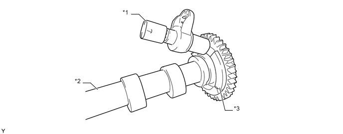
Text in Illustration *1 Camshaft Position Sensor *2 Camshaft *3 Timing Rotor - - 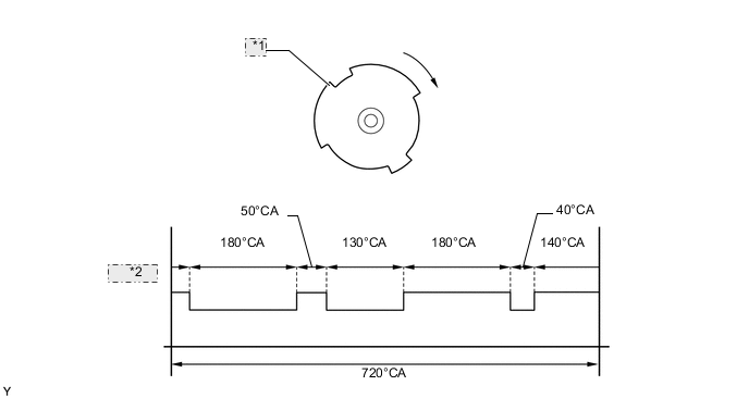
*1 Timing Rotor *2 Sensor Output Signal
-
-
Turbo Pressure Sensor Assembly
-
The turbo pressure sensor assembly consists of a semiconductor which utilizes the characteristics of a silicon chip that changes its electrical resistance when pressure is applied to it.
-
The sensor converts the intake air pressure into an electrical signal, and sends it to the ECM in an amplified form.
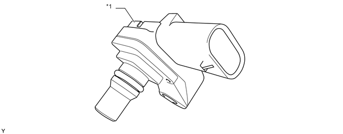
Text in Illustration *1 Turbo Pressure Sensor Assembly - -
-
-
Air Fuel Ratio Sensor
-
2 air fuel ratio sensors are used on this engine. One air fuel ratio sensor is located before the NOx Storage Reduction (NSR) catalyst and the other is located after the Diesel Particulate Filter (DPF) catalyst. The air fuel ratio sensor detects the oxygen concentration in the exhaust gas.
Text in Illustration *1 Air Fuel Ratio Sensor (before NSR Catalyst) *2 Air Fuel Ratio Sensor (after DPF Catalyst) *3 DPF Catalyst *4 NSR Catalyst
-
-
Glow Plug Controller
-
The glow plug controller independently controls the length of time for which the current is applied to the glow plug assemblies in each cylinder in accordance with signals from the ECM. Pulse Width Modulation (PWM) signals are used to control the glow plug assemblies.
-
The glow plug controller executes the request from the ECM and sends back diagnosis signals and conditions related to the request.
-
The glow plug controller and the ECM communicate with each other via the Local Interconnect Network (LIN).
Text in Illustration *1 Glow Plug Controller - -
-
-
Fuel Quantity Control Valve
-
The solenoid type fuel quantity control valve is mounted on the supply pump assembly.
-
The fuel quantity control valve is controlled according to signals from the ECM.
-
The flow rate of the fuel is controlled according to the amount the flow control valve is opened.
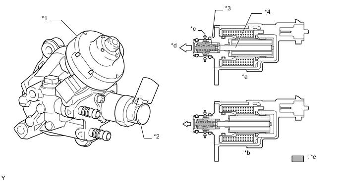
Text in Illustration *1 Supply Pump Assembly *2 Fuel Quantity Control Valve *3 Flow Control Valve *4 Tappet *a Flow Control Valve Open State *b Flow Control Valve Closed State *c Fuel Feed *d Fuel to Pump Element *e Fuel - -
-
-
Pressure Discharge Valve
-
The pressure discharge valve regulates the fuel pressure. In the pressure discharge valve, the ball valve opens and closes in accordance with the actuation signals from the ECM. Thus, it regulates the pressure by releasing excess pressure from the common-rail.
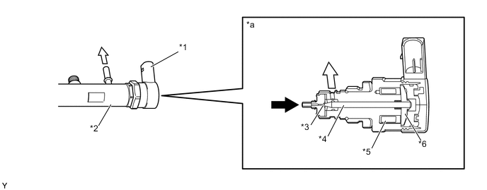
Text in Illustration *1 Pressure Discharge Valve *2 Common-rail *3 Ball Valve *4 Pressure Pin *5 Coil *6 Armature Plate *a Cross Section - - Fuel (from Common-rail) 
Fuel (Return)
-
-
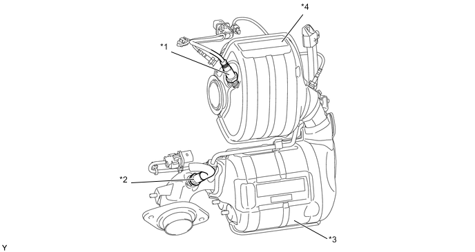
Swirl Control Valve Position Sensor and Actuator (for Swirl Control)
-
A swirl control valve position sensor and actuator (for swirl control) are located on the intake manifold.
-
The swirl control valve position sensor detects the swirl control valve opening angle.
-
The actuator (for swirl control) opens and closes the swirl control valve in accordance with ECM signals.
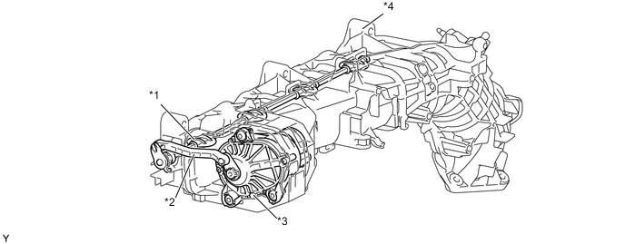
Text in Illustration *1 Swirl Control Valve *2 Linkage *3 Actuator and Swirl Control Valve Position Sensor Portion *4 Intake Manifold
-
-
-
OPERATION
-
Diesel Throttle Control
-
The opening of the diesel throttle valve is controlled by the ECM in accordance with the engine conditions.
-
The ECM controls the opening of the diesel throttle valve to reduce the noise and vibrations caused when stopping the engine.
-
-
Swirl Control
-
The ECM determines the swirl control valve position based on the engine conditions (engine speed and accelerator pedal effort). Then, the ECM controls the actuator (for swirl control), in order to open and close the swirl control valve.
-
In the minimum low load and low engine speed range, the ECM variably closes the swirl control valve to strengthen the swirl in the combustion chamber, promoting the mixture of fuel and air and stabilizing combustion.
-
The swirl control valve is fully opened when any of the following conditions is met:
-
Engine speed is more than approximately 2250 rpm.
-
Fuel injection rate is more than approximately 30 mg/stroke.
-
-
-
Turbocharger Control
-
The ECM calculates the optimal nozzle vane position in accordance with the driving conditions (engine speed, injection volume, atmospheric pressure, and engine coolant temperature etc.), and controls the nozzle vane position in accordance with the optimal nozzle vane position and the actual nozzle vane position signal from the nozzle vane position sensor.
-
-
Cooling Fan Control
-
The ECM activates the cooling fan relay to control the cooling fan in accordance with the engine coolant temperature, air conditioning condition*, engine speed and vehicle speed.
-
*: Models with air conditioning system
-
-
The cooling fan speed is controlled in 2 stages: low speed (series connection) and high speed (parallel connection).
-
-
Starter Control (Models with Entry and Start System)
-
When the driver pushes the engine switch once and the power management control ECU detects a start signal, the power management control ECU will output the ACCD and STAR signals and begin cranking. Also, the driver can continue cranking for up to 30 seconds by pushing and holding the engine switch.
-
If the engine speed reaches approximately 800 rpm, the ECM will judge that the engine has started and will send a signal to the power management control ECU using CAN communication. The power management control ECU will then stop the operation of the starter.
-
This system will cut off the power current which activates the accessories while the engine is being cranked. This prevents the intermittent blinking of the accessory lights caused by the voltage instability that occurs during engine cranking.
-
This system has the following protections:
-
The starter will not operate if the engine is operating normally.
-
When the engine switch is pushed and held, cranking stops once the engine speed reaches a pre-determined level. This prevents the starter from over-revving.
-
When the engine does not start even after approximately 6 seconds of starter operation, the power management control ECU cancels the starter relay output. Furthermore, if the engine does not start after the engine switch has been pushed and held and cranking has continued for 30 seconds, cranking will be canceled in order to protect the starter.
-
It will not be possible to operate the starter for 2 seconds after engine starting has failed and cranking has been canceled. This helps to protect the starter.
-
-
-
Oil Maintenance Management System
-
Engine Oil Maintenance Reminder Display
-
The soot volume in the engine oil is calculated based on the engine operating conditions by the ECM. Based on the calculated soot volume, the ECM transmits a signal to the combination meter that indicates that a reminder is necessary. This reminder informs the driver that it is necessary to change the engine oil.
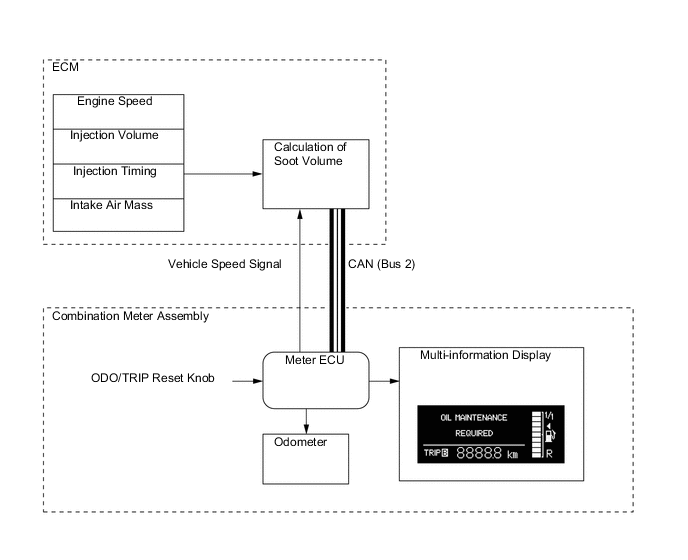
Tech Tips
-
Since this system is controlled based on engine operating conditions, the "OIL MAINTENANCE REQUIRED" message may be displayed on the multi-information display before driving 20000 km (10000 km for Turkey, Serbia, Montenegro, Macedonia and Bosnia and Herzegovina) (the maximum travel distance after oil maintenance). If the "OIL MAINTENANCE REQUIRED" message is displayed, the oil and oil filter should be replaced immediately.
-
This system does not determine the deterioration of the engine oil based on the elapsed time. Even if the "OIL MAINTENANCE REQUIRED" message does not illuminate, the engine oil and oil filter should be changed at 2-year intervals at the maximum.
-
-
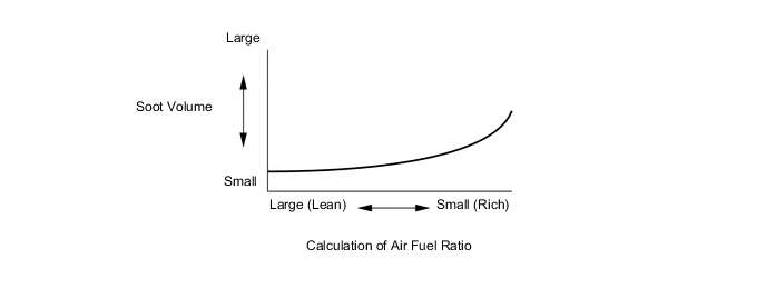
Soot Volume Calculation Method
-
The soot volume largely depends on the injection ending timing and the air fuel ratio. The ECM calculates soot volume from this information as shown in the graph below:
-
-
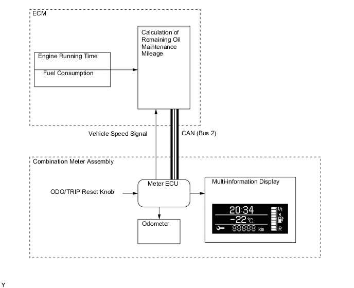
Remaining Oil Maintenance Mileage Display
-
The remaining oil maintenance mileage is calculated based on the driving pattern (fuel consumption, engine running time and vehicle mileage) by the ECM. In addition, the ECM displays the remaining oil maintenance mileage on the multi-information display.
-
The calculated remaining oil maintenance mileage is counted down. When the calculated remaining oil maintenance mileage counts down to 1000 km, "OIL MAINTENANCE REQUIRED SOON" is displayed on the multi-information display to urge the driver to change the oil.

-
In addition, when the calculated remaining oil maintenance mileage becomes less than 1000 km, the black and white of the mileage on the multi-information display are inverted.

-
After the calculated remaining oil maintenance mileage counts down to 0 km, the mileage showed on the display indicates a negative number.

Tech Tips
-
The calculated oil maintenance mileage may not reach 20000 km (10000 km for Turkey and the Balkans) depending on the driving conditions (low speed or bad fuel consumption) in order to maintain the quality of the engine oil.
-
When in ODO mode, the remaining oil maintenance mileage is displayed on the multi-information display for 5 seconds after the ignition switch is turned to ON. Also, the driver can display the mileage by operating the ODO/TRIP reset knob.
-
-
-