BODY STRUCTURE
-
FUNCTION
-
Impact Absorbing Structure for Frontal Collision
-
A structure that ensures collision energy absorption efficiency, dissipates impact, and minimizes cabin deformation during a frontal collision has been achieved.
-
Impact energy during a frontal collision will first be dispersed into the left and right front side members by the front bumper reinforcement. Then, it will be dispersed again into the rocker panel and front under floor.
-
Impact energy received by the upper member will be dispersed into the front door beltline reinforcements and front body pillar reinforcements.
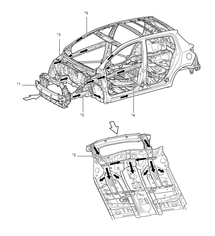
Text in Illustration *1 Front Bumper Reinforcement *2 Front Side Member *3 Upper Member *4 Front Door Beltline Reinforcement *5 Front Body Pillar Reinforcement - - 
Path of Collision Energy 
Frontal Collision
-
-
Impact Absorbing Structure for Side Collision
-
A structure that ensures collision energy absorption efficiency, dissipates impact, and minimizes cabin deformation during a side collision has been achieved.
-
Ultra high strength steel sheet is used for the rocker outer reinforcement and center body pillar upper hinge reinforcement, and high strength steel sheet is used for the center body pillar outer reinforcement and rail outer reinforcement, to ensure high strength.
-
By providing bulkheads inside the rockers and thus controlling rocker bending, cabin deformation suppression has been aimed for.
-
Optimal placement of the door side impact protection beams enable a construction that efficiently transmits load.
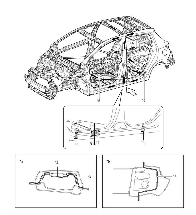
Text in Illustration (5-Door Models:) *1 Rocker Outer Reinforcement *2 Center Body Pillar Upper Hinge Reinforcement *3 Center Body Pillar Outer Reinforcement *4 Bulkhead *5 Front Door Side Impact Protection Beam *6 Rear Door Side Impact Protection Beam *a A-A Cross Section *b B-B Cross Section Path of Collision Energy Side Collision 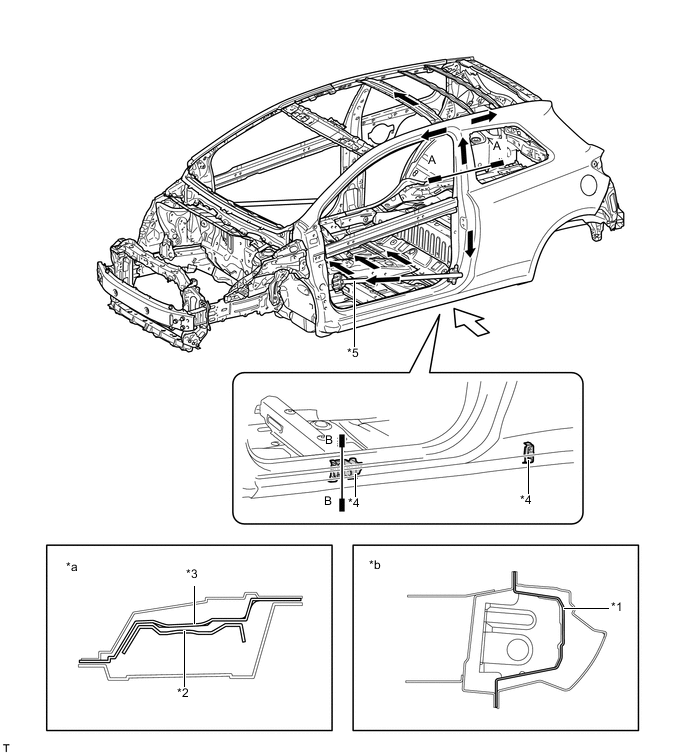
Text in Illustration (3-Door Models:) *1 Rocker Outer Reinforcement *2 Center Body Pillar Upper Hinge Reinforcement *3 Center Body Pillar Outer Reinforcement *4 Bulkhead *5 Front Door Side Impact Protection Beam - - *a A-A Cross Section *b B-B Cross Section Path of Collision Energy Side Collision
-
-
Lessening Pedestrian Injury
-
A front bumper energy absorber and a front bumper energy absorber sub-assembly are provided in front of the front bumper reinforcement and below the lower radiator support. This structure helps lessen the impact applied to the legs of the pedestrians.
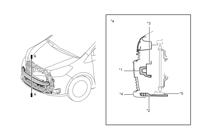
Text in Illustration *1 Front Bumper Energy Absorber *2 Front Bumper Energy Absorber Sub-assembly *3 Front Bumper Reinforcement *4 Front Bumper Cover *5 Lower Radiator Support - - *a A-A Cross Section - - -
A pantograph construction, which absorbs the impact it receives while collapsing, is used in the hood reinforcement. During a collision with a pedestrian, a space for the pedestrian's head to stroke is ensured, and helps reducing the predicted impact to the pedestrian's head.
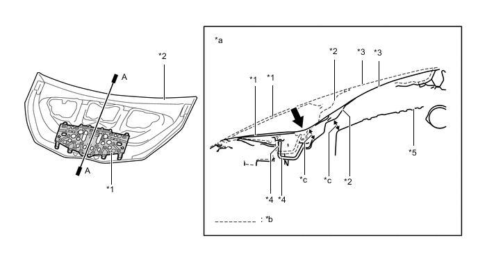
Text in Illustration *1 Hood Reinforcement *2 Hood Inner Panel *3 Hood Sub-assembly *4 Hood Striker *5 Engine - - *a A-A Cross Section *b Before Collision *c Space - - Impact - - -
An impact absorbing bracket (front apron to cowl side member plate) is used for the mounting portion of the front fender panel to absorb impact energy to the head of the pedestrian in a collision, thus helps dampening the impact to the head.
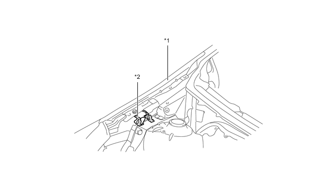
Text in Illustration *1 Front Fender Panel (Front Fender Sub-assembly) *2 Impact Absorbing Bracket (Front Apron to Cowl Side Member Plate) -
The cowl uses an open section structure that collapses easily in an impact from the top, thus helps reducing the impact to and head injuries sustained by a pedestrian in an accident.
-
A certain amount of depth has been provided internally under the location where the windshield wiper is mounted to allow the windshield wiper to be pushed downward if a pedestrian's head collides with the area, thus helps reducing the impact to their head during a collision.
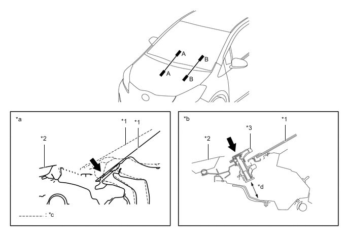
Text in Illustration *1 Windshield *2 Hood Sub-assembly *3 Windshield Wiper - - *a A-A Cross Section *b B-B Cross Section *c Before Collision *d Space Impact - - -
In order to help reduce collision impact for pedestrian, a space has been provided under the left and right hood hinge arms so that they can move if a pedestrian's head collides with the hood.
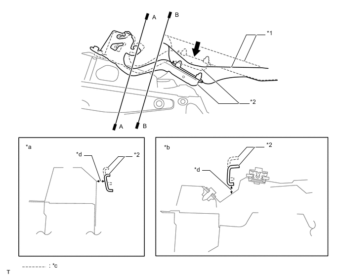
Text in Illustration *1 Hood Sub-assembly *2 Hood Hinge Assembly *a A-A Cross Section *b B-B Cross Section *c Before Collision *d Space Impact - -
-
-
Aerodynamics
-
Various types of airflow routing parts are provided under the floor to control airflow.
-
Spats are fitted at the front of the front and rear tires to direct the airflow, and this reduces air turbulence into the wheel house, leading to ensured straight driving stability at high speeds.
-
The outer rear view mirror shape has been optimized to increase the aerodynamics.
-
A rear spoiler sub-assembly is provided, giving a rectifying effect and allowing superior aerodynamic performance.
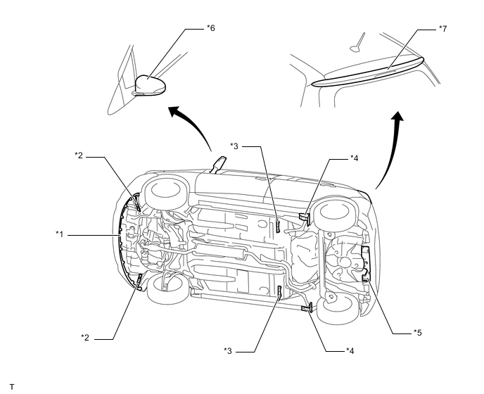
Text in Illustration *1 Front Spoiler Cover *2 Front Spat (Front Wheel Opening Extension Pad) *3 Center Spat (Rocker Panel Moulding Protector) *4 Rear Spat (Rear Wheel Opening Extension Pad) *5 No. 1 Floor Under Cover *6 Outer Rear View Mirror Assembly *7 Rear Spoiler Sub-assembly - -
-
-
-
CONSTRUCTION
-
Lightweight and Highly Rigid Body
-
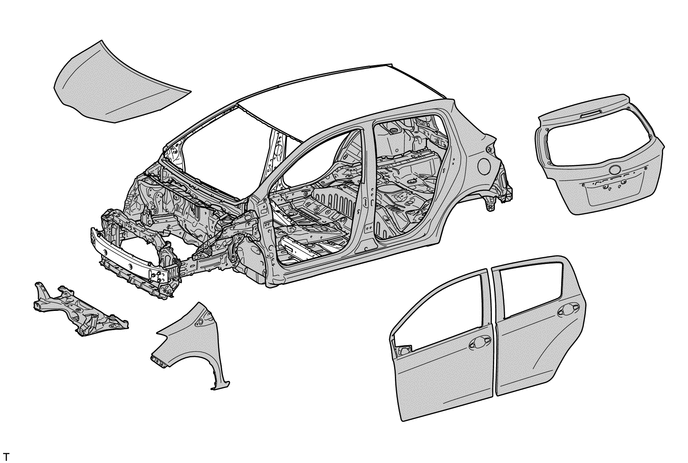
High strength steel sheet and ultra high strength steel sheet are used in order to achieve excellent body rigidity and a lightweight body.
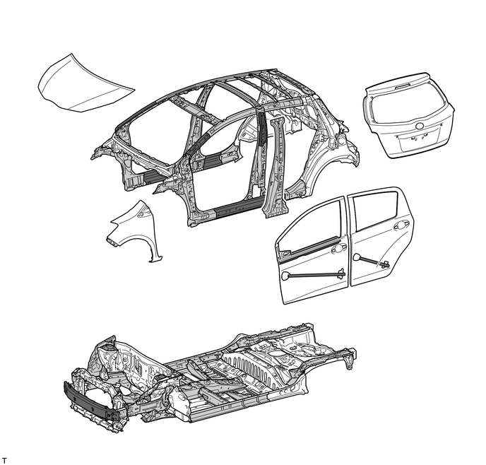
Text in Illustration (5-Door Models:) 
High Strength Steel Sheet 
Ultra High Strength Steel Sheet 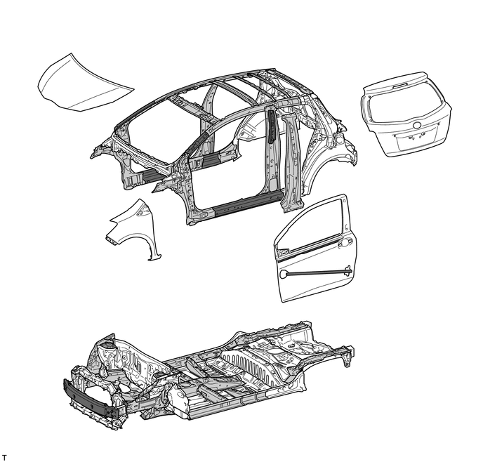
Text in Illustration (3-Door Models:) High Strength Steel Sheet Ultra High Strength Steel Sheet
-
-
Body Shell Construction
-
Sufficient rigidity has been ensured by using the outer cowl top panel as a framework cross member to smoothly connect the left and right front suspension towers. In this way, good driving stability has been achieved.
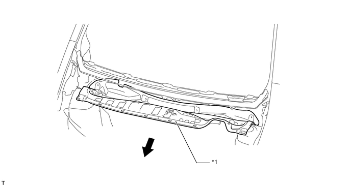
Text in Illustration *1 Outer Cowl Top Panel - - Front - - -
The roof side outer reinforcements consist of a close section structure and are joined with the rear absorber plates to deliver rigidity to the areas where the rear suspension is installed.
-
The back door circumference employs a close section structure and corner reinforcements to make the back door opening rigid.
-
In order to provide rigidity against counter twisting forces while delivering excellent driving stability, the roof side inner rear and lower back reinforcements have been joined to the lower extensions, and also the lower back reinforcements, wheel house inner gussets and side outer panels have been joined to the rear floor side members.
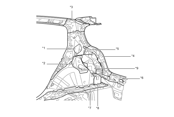
Text in Illustration *1 Roof Side Outer Reinforcement *2 Rear Absorber Plate *3 Corner Reinforcement *4 Lower Extension *5 Roof Side Inner Rear *6 Lower Back Reinforcement *7 Rear Floor Side Member *8 Wheel House Inner Gusset *9 Side Outer Panel - -
-
-
Anti-corrosion Sheet Steel
-
Anti-corrosion sheet steel is used as in the following illustration:
Text in Illustration (5-Door Models:) Anti-corrosion Sheet Steel - - 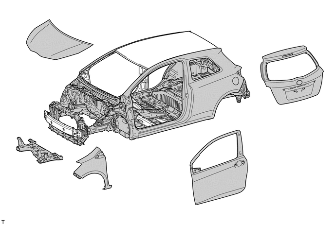
Text in Illustration (3-Door Models:) Anti-corrosion Sheet Steel - -
-
-
Wax and Anti-chipping Application
-
Wax is applied to front end of hood sub-assembly, edge of the door lower portion and fuel filler lid hinge to improve rust-resistant performance.
-
To protect the paint from chipping, anti-chipping paint is applied to the rockers and the front end of the hood sub-assembly.
Text in Illustration *1 Fuel Filler Lid Hinge - - 
Wax Anti-chipping Paint
-
-
Under Coat
-
Acrylic resin is applied to the under side of the body, inside the wheel housing and other parts that are susceptible to stone chipping damage, thus improving the rust-resistant performance of these areas.
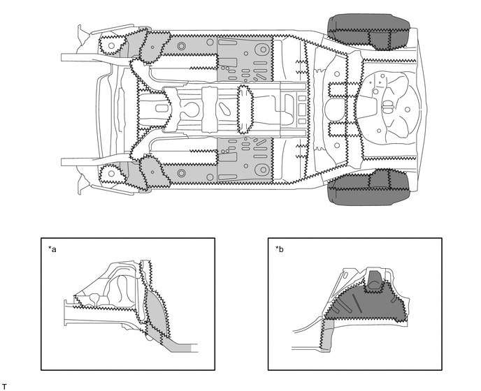
Text in Illustration *a Front Wheel House *b Rear Wheel House 
Edge Seal Acrylic Resin Coating Area Acrylic Resin Coating Area (Thick Coating) - -
-
-
Low Vibration and Low Noise Body
-
A hood insulator is provided on the rear of the hood sub-assembly. This achieves excellent sound insulation performance.
-
An outer dash panel insulator, an outer No. 2 dash panel insulator and a fender liner silencer are provided. These reduce the amount of engine noise leaking into and out of the cabin.
-
A front fender side panel protector is provided. This prevents road noise from entering the cabin, and achieves superior quietness.
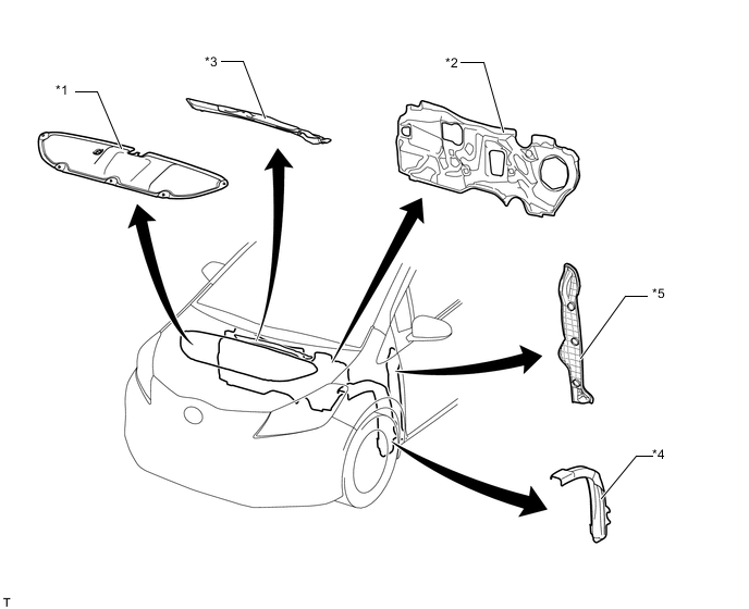
Text in Illustration *1 Hood Insulator *2 Outer Dash Panel Insulator *3 Outer No. 2 Dash Panel Insulator *4 Fender Liner Silencer *5 Front Fender Side Panel Protector - - -
To reduce the amount of road noise, engine noise and droning sound that enters the cabin, the floor panel is coated with a vibration damping coat.
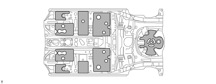
Text in Illustration Spray Type Damping Material Application Area - - -
A sound insulation material is used in the body frame profile, thus reducing the various noises which intrude from the outside of the vehicle to the inside of the cabin.
-
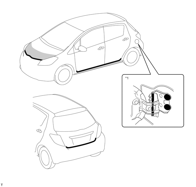
Rocker panel moulding is provided on the underside of the rockers, thus reducing the sound of sand and pebbles thrown up from the road.
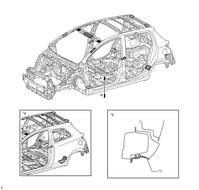
Text in Illustration *1 Rocker Panel Moulding - - *a 3-door Models *b A-A Cross Section Polyurethane Form Expanded Form Polyethylene Sealer - -
-
-
Parts with Low Repair Cost
-
A crush box structure is used to reduce body deformation during minor collisions. A structure with screw connections is provided for the front bumper arm sub-assembly and the rear bumper arm reinforcement to enable easy removal and installation, thus achieving simpler servicing operation and repair cost reduction.
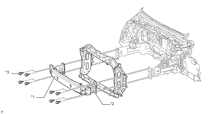
Text in Illustration (Front:) *1 Front Bumper Reinforcement *2 Front Bumper Arm Sub-assembly *3 Bolt - - 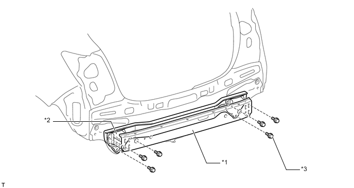
Text in Illustration (Rear:) *1 Rear Bumper Reinforcement *2 Rear Bumper Arm Reinforcement *3 Bolt - -
-
-