AIR CONDITIONING SYSTEM
-
OUTLINE
-
Air Conditioning System
-
A Manual air conditioning system or automatic air conditioning system using left/right independent temperature control is used.
-
A Positive Temperature Coefficient (PTC) heater control is provided. This improves heating performance.
-
-
Combustion Type Power Heater
-
While the 1ND-TV engine offers excellent combustion efficiency, it generates less heat. In order to provide adequate heating effect, a combustion type power heater is provided.
-
-
-
SPECIFICATION
-
Performance
Air Conditioning Type Manual Automatic Heater Heater Output W 4600/4700* ← Air Flow Volume m3/h
280/290* ← Power Consumption W 170 180 Cooler Cooling Capacity W 4430 4450 Air Flow Volume m3/h
420 430 Power Consumption W 210 230
-
*: Models with PTC Heater
-
-
Ventilation and Heater Radiator Unit Sub-assembly
Heater Radiator Unit Sub-assembly Type Straight Flow Aluminum (SFA)-II Size: W x H x L mm (in.) 201.5 x 140 x 27 (7.9 x 5.5 x 1.1) Fin Pitch mm (in.) 1.8 (0.07) Blower with Fan Motor Sub-assembly Motor Type K62-12.5T*1 / K62-11.5T*2 Fan Type Semi Sirocco Fan Size: Dia. x H mm (in.) 145 x 65 (5.7 x 2.6)
-
*1: Models with Manual Air Conditioning System
-
*2: Models with Automatic Air Conditioning System
-
-
Air Conditioning
Cooler Condenser Assembly Type Global Inner-fin Condenser (GIC)*1
Multi-Flow (MF)-IV (Sub Cool)*2
Size: W x H x L mm (in.) 520 x 325 x 11.5 (20.5 x 12.8 x 0.5)*1
498 x 324.6 x 16 (19.6 x 12.8 x 0.6)*2
Fin Pitch mm (in.) 2.5 (0.1)*1
2.75 (0.1)*2
No. 1 Cooler Evaporator Sub-assembly Type Revolutionary super-Slim structure (RS) Size: W x H x L mm (in.) 199.3 x 231 x 38 (7.8 x 9.1 x 1.5) Fin Pitch mm (in.) 2.6 (0.1) Compressor with Pulley Assembly Type 5TSE10C Pulley Damper Limiter (DL) Compressor Oil Type ND8*3, ND12*4 Refrigerant Type HFC-134a*3, HFO-1234yf*4 Charge Volume g 360+/-30*3, 350+/-30*4 Clean Air Filter Pollen Removal Type
-
*1: Models with 1KR-FE Engine and 1NR-FE Engine
-
*2: Models with 1ND-TV Engine
-
*3: Models using HFC-134a refrigerant
-
*4: Models using HFO-1234yf refrigerant
-
-
-
MAIN FEATURES
-
The air conditioning system has the following features:
Item Outline High Performance
-
Neural network control is used so passengers can control the air conditioning accurately for maximum comfort.*1
-
The blower control has 7 levels in manual mode and 31 levels in auto mode for more precise control.*1
-
The Positive Temperature Coefficient (PTC) heater control is used. This system contains a PTC heater (quick hater assembly) that heats the air that has passed through the heater radiator unit sub-assembly to ensure proper heater performance.*2
-
In order to provide adequate heating effect, a combustion type power heater is provided.*3
-
A pollen removal type clean air filter is used as clean air filter.
Lightweight A bus connector (air conditioning harness assembly) with a built-in IC is used in a lightweight wire harness design with a reduced number of wires. The use of this connector means that pulse pattern type servo motors are used.*1 Compact
-
A semi-center location air conditioning unit in which the No. 1 cooler evaporator sub-assembly, heater radiator unit sub-assembly and PTC heater (quick hater assembly)*2 are placed in the vehicle's longitudinal direction is used.
-
A blower motor with a built-in blower motor controller is used in a compact construction.*1
Others
-
The following parts are used to ensure high cooling or heating performance while realizing a compact and lightweight construction.
-
Revolutionary super-Slim structure (RS) type No. 1 cooler evaporator sub-assembly
-
Straight Flow Aluminum (SFA)-II type heater radiator unit sub-assembly
-
Global Inner-fin type cooler condenser assembly*4
-
Multi-Flow (MF)-IV type cooler condenser assembly*5
-
Continuously variable capacity type compressor with pulley assembly (5TSE10C type)
-
*1: Models with Automatic Air Conditioning System
-
*2: Models with PTC Heater
-
*3: Models with Combustion Type Power Heater
-
*4: Models with 1KR-FE Engine and 1NR-FE Engine
-
*5: Models with 1ND-TV Engine
-
-
Combustion Type Power Heater
-
The combustion type power heater is provided between the engine and the heater radiator unit sub-assembly. Air and fuel are introduced into the heater's combustion chamber, and a glow plug is used to ignite this mixture. By heating the engine coolant that flows around the combustion chamber, this system ensures the heating effect. The system can be activated or deactivated by turning on or off the power heater switch (heater switch assembly).
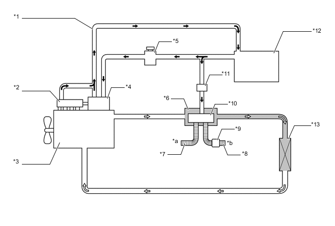
Text in Illustration *1 Fuel Return Tube *2 Common Rail Assembly *3 Engine *4 Injection or Supply Pump Assembly *5 Fuel Filter Cap Assembly *6 Heater Assembly *7 Intake Pipe *8 Exhaust Pipe *9 Muffler *10 Combustion Chamber *11 Fuel Pump *12 Fuel Tank Assembly *13 Heater Radiator Unit Sub-assembly - - *a Intake Air *b Exhaust Gas 
Fuel 
Engine Coolant Tech Tips
-
When the power heater is turned on or off, some white smoke and a slight odor may be emitted from the exhaust located under the floor.
-
If the power heater is being used under extremely cold conditions, vapor may be visible from the exhaust.
-
It is not recommended to restart the power heater for 10 minutes after the power heater is turned off. Otherwise, a noise may be heard as the heater ignites.
-
Do not turn the power heater on and off repeatedly within 5-minute intervals as this can shorten the life of the heater components.
-
If the engine is to be turned on and off repeatedly within short intervals (such as when being used for delivery purposes), turn the power heater switch (heater switch assembly) off.
-
-
-
-
PRECAUTION
-
Precaution for Refrigerant HFO-1234yf
-
The parts used in the refrigerant cycle, the compressor oil, etc. of a HFO-1234yf system are not compatible with a conventional HFC-134a system.
-
Always use HFO-1234yf as the refrigerant.
CAUTION:
-
Do not charge the system with refrigerant near open flames, as HFO-1234yf is combustible.
-
When charging the system with refrigerant, make sure the area is well ventilated (especially be careful in areas where the gas can easily accumulate such as under lifts and in garage pits, as the gas is heavier than air).
-
Follow any local regulations regarding combustible gases.
-
Be sure to use a refrigerant recovery unit that is compatible with HFO-1234yf systems.
Tech Tips
The shape of the service port for refrigerant charging has an exclusive design conforming to international standards for HFO-1234yf to prevent improper refrigerant charging.
-
-
-
Compressor Oil (Models using HFO-1234yf refrigerant)
-
Always use ND12 as the compressor oil.
Note
The oil used for HFC-134a systems (ND8) does not work well in HFO-1234yf systems. If the oil used for HFC-134a systems (ND8) is used in the HFO-1234yf system, it will result in degradation of the refrigerant and deterioration of resin parts.
-
When parts of the air conditioning system are removed, quickly block off any areas that are exposed to the outside air with plugs, vinyl tape, etc., as the oil used for HFO-1234yf systems absorbs moisture easily.
-
Do not allow the compressor oil to spray, as the oil used for HFO-1234yf systems has harmful effects on acrylic resins.
-
-