CHARGING SYSTEM(w/ Stop And Start System)
-
FUNCTION OF MAIN COMPONENTS
Component Function Battery State Sensor Assembly Sends the auxiliary battery voltage, current, battery fluid temperature, SOC, etc. to the ECM. ECM Sends a generated voltage adjustment signal to the generator assembly based on electrical load condition, auxiliary battery condition and driving conditions. Generator Assembly Sends information about its own malfunctions to the ECM. -
SYSTEM CONTROL
-
Charging control is performed by the ECM.
-
Charging control selects an optimal control mode according to the auxiliary battery status and vehicle conditions. The provided control modes are basic control mode, supplementary charging mode and refresh charging mode.
-
Basic Control Mode
-
The ECM decreases the generated voltage during acceleration and increases it during deceleration in order to reduce the amount of engine load caused by the generator assembly, thus improving fuel efficiency.
-
The ECM detects the electrical load condition (air conditioning system, wiper system, taillight switch on, etc.).
-
The battery state sensor assembly detects the condition of the auxiliary battery and transmits this information to the ECM. Based on this signal, the ECM makes a judgement about the condition of the auxiliary battery.
-
Based on the electrical load condition and the condition of the auxiliary battery, the ECM calculates the voltage to request and sends a generated voltage adjustment signal to the generator assembly.
-
During idling and when driving at a constant speed, the ECM adjusts the generated voltage to bring the current integrated value* closer to the target value.
Tech Tips
*: Integrated value of the auxiliary battery input/output current as detected by the battery state sensor assembly.
-
-
Supplementary Charging Mode
-
This mode charges the auxiliary battery using constant voltage control if the auxiliary battery capacity is low.
-
-
Refresh Charging Mode
-
This mode suppresses decreases in the auxiliary battery lifespan by regularly*1 performing constant voltage control to charge the auxiliary battery. Also, the operation time of constant voltage control is longer in this mode compared to supplementary charging mode.*2
Tech Tips
*1: Accumulated driving time become approximately 30 hours.
*2: Constant voltage control is also performed for a long time when the auxiliary battery capacity is low after the auxiliary battery is replaced or the vehicle is left for a long period of time.
-
-
-
-
FUNCTION
-
The ECM communicates with the generator assembly via LIN communication, sending and receiving multiple signals in order to finely control the voltage generated by the generator assembly.
-
The battery state sensor assembly detects the temperature of the auxiliary battery and sends a signal to the ECM to enable judgement of the conditions for entering constant voltage generation mode.
-
-
PROTECTION CONTROL
-
Due to fail-safe operation, when a sensor malfunctions, basic control is stopped and the system enters constant voltage generation mode. Also, even outside of supplementary charging mode, due to operating circumstances such as auxiliary battery condition and electrical load, basic control may be stopped and the system may enter constant voltage generation mode.
Conditions for Shifting to Constant Voltage Generation Mode other than Supplementary Charging Mode Judgement Condition Reasoning Vehicle Behavior Low Auxiliary Battery Capacity If the auxiliary battery state is bad, the basic control discontinues, and the decrease in auxiliary battery capacity is prevented. If auxiliary battery temperature is too low or high, that case becomes cause of auxiliary battery capacity decrease or auxiliary battery lifetime decrease. "Basic Control Stops" to "Constant Voltage Generation Mode" Low or High Auxiliary Battery Temperature Wipers Operating, Blower Motor Operating (Over High Load), or Taillight Switch On Avoid a sense of driver's incongruity depending on voltage fluctuation (To secure market appeal and stable electric power supply). Each Sensor Malfunction In case of sensor malfunction, basic control discontinues, to prevent auxiliary battery capacity decrease. "Basic Control Stops" to "Constant Voltage Generation Mode (Autonomous Generation Mode*)" Generator Assembly Malfunction In case of generator assembly malfunction, basic control discontinues, to prevent auxiliary battery capacity decrease and to protect the auxiliary battery. Communication Failure (LIN Communication between the Generator Assembly, ECM and the Battery State Sensor Assembly) In case of LIN communication failure between ECM to generator assembly or to battery state sensor assembly, basic control discontinues, to prevent auxiliary battery capacity decrease and to protect the auxiliary battery. Tech Tips
*: In this mode, voltage is generated at a constant level using the IC regulator function built into the generator assembly.
-
-
CONSTRUCTION
-
Generator Assembly
Generator Assembly Specification Item Specification Generator Type cSC0 Rated Voltage (V) 12 Output Rated (A) 100 Initial Output Starting Speed (rpm) Max. 1300 -
Auxiliary Battery
-
A European Norm (EN) battery for the auxiliary battery is provided.
-
The ISS* type auxiliary battery is a suitable battery for the repeated engine starts that are performed by the stop and start system.
CAUTION:
When replacing the auxiliary battery, replace it with an ISS type battery or an equivalent battery intended for use with the stop and start system. It is dangerous to use a battery not intended for use with the stop and start system, as the engine may not stop/start correctly, or the battery could burst.
Tech Tips
*: ISS refers to the stop and start system.
Auxiliary Battery Specification Item Specification Battery Type*1 LN2-ISS*2 LN3-ISS*3 Rated Voltage (V) 12 12 20 Hour Rate Capacity (20HR) (Ah) 60 70 Cold Cranking Ampere (CCA)*4 (A) 540 640 Exhaust Method Each Cell Each Cell Indicator Nothing Nothing Tech Tips
*1: For European Norm (EN) batteries, this refers to the battery size.
*2: Except destination package models for Germany.
*3: Destination package models for Germany.
*4: Value indicates low-temperature starting performance.
-
-
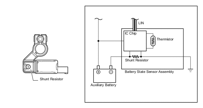
Battery State Sensor Assembly
-
The battery state sensor assembly installed on the negative (-) battery terminal calculates the current, voltage, auxiliary battery temperature, SOC (auxiliary battery charging percentage), and self-diagnosis result and sends these signals to the ECM via LIN communication.
-
To detect the current, a shunt resistor installed inside the battery state sensor assembly is used to convert and calculate the voltage generated in the shunt resistor due to the auxiliary battery charge and discharge current.
-
The auxiliary battery temperature is calculated from the resistance value of the thermistor built in the battery state sensor assembly.
-
-