CHARGING SYSTEM
-
SYSTEM CONTROL
-
Charging lowers the generated voltage when the vehicle is accelerating, and raises the generated voltage when the vehicle is decelerating. This reduces the load applied to the engine by the generator while it is generating electricity, resulting in improved fuel economy. During idle or constant-speed driving, this system regulates the generated voltage in order to bring the amperage estimation value closer to the target value.
-
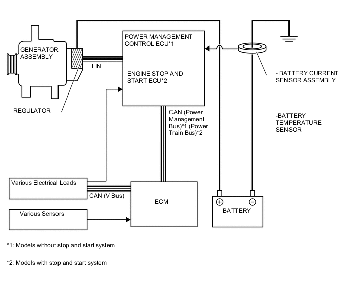
This control consists of the power management control ECU*1 (engine stop and start ECU*2), battery current sensor, battery temperature sensor, generator and various sensors and switches.
-
The power management control ECU*1 (engine stop and start ECU*2) detects driving conditions based on signals from various sensors and switches, and detects charging conditions based on signals from the generator, battery current sensor and battery temperature sensor. The power management control ECU*1 (engine stop and start ECU*2) then outputs signals to the regulator to control the generated voltage of the generator.
-
The power management control ECU*1 (engine stop and start ECU*2) stops the charging control and the generator switches to normal power generation mode under the following conditions:
-
Low battery capacity
-
Low or high battery temperature
-
Wipers operating or blower motor operating with taillight relay on
-
Battery current sensor assembly or battery temperature sensor malfunctions
-
Engine started
-
Battery charged for approximately 2 hours*1 (2 hours*2).
-
Accumulated driving time becomes approximately 20 hours
Tech Tips
*1: Models without stop and start system
*2: Models with stop and start system
-
-
-
CONSTRUCTION
-
Generator Assembly
-
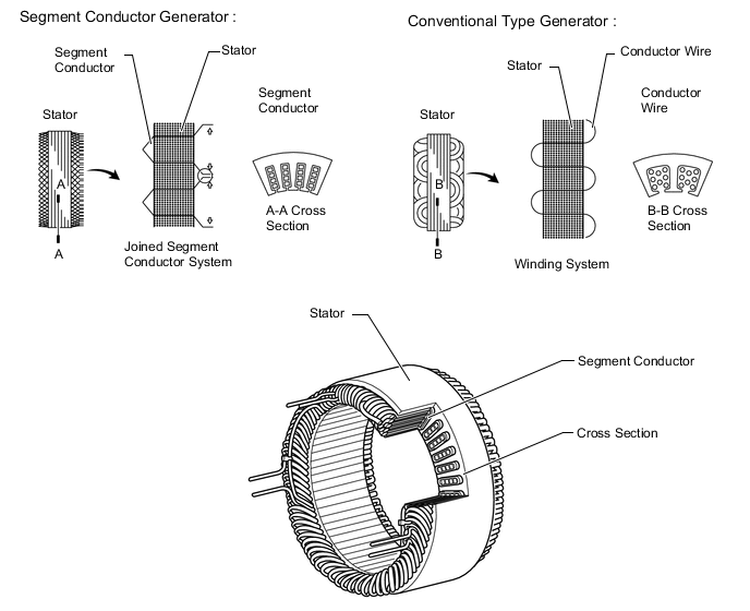
This generator assembly has a joined segment conductor system in which multiple segment conductors are welded together to form the stator. Compared to the conventional winding system, the electrical resistance is reduced due to the shape of the segment conductors, and their arrangement helps to make the generator assembly compact.
-
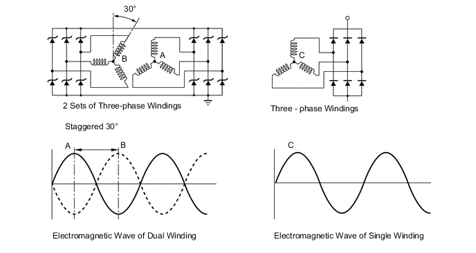
The starter coil for the SC0Z type and SC120 type generator assembly uses a dual winding system to reduce both electrical noise (ripple and spike) and magnetic noise (a hum that is heard as generator assembly load is increased). This system consists of 2 sets of three-phase windings whose phases are staggered by 30°. Both electrical noise and magnetic noise are reduced because the electromagnetic waves that the respective windings generate have opposite polarities. However the electrical power generated does not cancel itself out, due to the use of separate rectifiers. The opposite polarities that are generated can be seen below.
-
-
Auxiliary Battery
-
For the auxiliary battery, a European Norm (EN) battery as well as a JIS specification battery are specified.
-
The ISS* type auxiliary battery is a suitable battery for the repeated engine starts that are performed by the stop and start system.
CAUTION:
When replacing the auxiliary battery, replace it with an ISS type battery or an equivalent battery intended for use with the stop and start system. It is dangerous to use a battery not intended for use with the stop and start system, as the engine may not stop/start correctly, or the battery could burst.
Tech Tips
*: ISS refers to the stop and start system.
Auxiliary Battery Specification Item Specification Battery Type*1 46B24L(S)*2 55D23L-ISS*3 85D26L*4 LN1*5 LN2-ISS*6 LN3-ISS*7 Rated Voltage (V) 12 12 12 12 12 12 20 Hour Rate Capacity (20HR) (Ah) 45 60 65 45 60 70 Cold Cranking Ampere (CCA)*8 (A) 325/295 320 490 325 540 640 Exhaust Method Each Cell All Cells Combined All Cells Combined All Cells Combined Each Cell Each Cell Indicator Nothing Nothing Nothing Nothing Nothing Nothing Tech Tips
*1: For European Norm (EN) batteries, this refers to the battery size.
*2: TMC-made vehicles without stop and start system.
*3: TMC-made M/T vehicles with stop and start system.
*4: TMC-made CVT vehicles with stop and start system, or destination package models for Germany.
*5: TMMF-made vehicles without stop and start system.
*6: TMMF-made M/T vehicles with stop and start system.
*7: TMMF-made CVT vehicles with stop and start system, or destination package models for Germany.
*8: Value indicates low-temperature starting performance.
-
-
Battery Current Sensor Assembly
-
Installed on the negative terminal of the battery, this sensor detects the amount of charging and discharging amperage of the battery and sends signal to the ECM. Based on this signal, the ECM calculates the battery capacity.
-
A Hall IC is used for detecting the amount of charging and discharging amperage. The changes that occur in the magnetic flux density in the core as a result of the charging and amperage of the battery are converted and output as voltage.
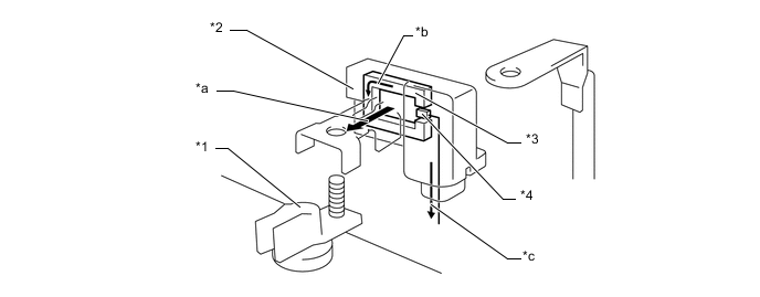
Text in Illustration *1 Negative Terminal of the Battery *2 Battery Current Sensor Assembly *3 Core *4 Hall IC *a Charge/discharge Current *b Magnetic Field *c Charge/discharge Amount Signals - - 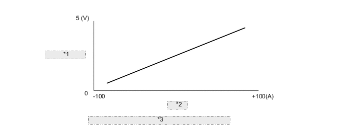
*1 Output Voltage *2 Current *3 Characteristic of BATTERY CURRENT SENSOR ASSEMBLY
-
-
Battery Temperature Sensor
-
The battery temperature sensor is built into the battery current sensor assembly.
-
The battery characteristic (battery internal resistance) of taking in current for charging varies according to battery electrolyte temperature. If the electrolyte temperature is too low or too high, the battery internal resistance will increase, resulting in early deterioration. To prevent this, the battery temperature sensor changes its resistance as shown below to detect the temperature.
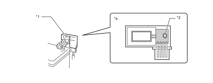
Text in Illustration *1 Battery Temperature Sensor Portion *2 Battery Current Sensor Assembly *a Battery Current Sensor Assembly Cross Section - - 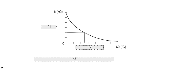
*1 Resistance *2 Battery Temperature *3 Characteristic of BATTERY TEMPERATURE SENSOR ASSEMBLY
-
-