POWER STEERING SYSTEM
-
FUNCTION OF MAIN COMPONENTS
-
The main components of the EPS system are as follows:
Component Function Steering Column Assembly Torque Sensor Detects the twist of the torsion bar, calculates the torque that is applied to the torsion bar by changing it into an electrical signal, and outputs this signal to the power steering ECU assembly. Power Steering Motor Generates assist torque in accordance with a current received from the power steering ECU assembly. Reduction Mechanism Reduces the speed of the power steering motor through the use of a worm gear and a wheel gear and transmits it to the column shaft. Power Steering ECU Assembly Actuates the power steering motor mounted on the steering column assembly to provide assist torque, based on the signals received from various sensors and ECUs. ECM Transmits the engine speed signal to the power steering ECU assembly. Skid Control ECU Transmits the vehicle speed signal to the power steering ECU assembly. Engine Stop And Start ECU*1 Transmits the control mode signal to the power steering ECU assembly. Combination Meter Assembly EPS Warning Light Illuminates to alert the driver when the power steering ECU assembly detects a malfunction in the EPS system. Buzzer Sounds to alert the driver when the power steering ECU assembly detects a malfunction in the EPS system. Network Gateway ECU*2 Sends signals to and receives signals from the ECM. *1: Models with stop and start system
*2: Models with 2ZR-FE engine
-
-
SYSTEM CONTROL
-
The EPS system has the following controls:
Control Outline Basic Control Calculates the assist current from the steering torque value and the vehicle speed, and actuates the power steering motor. Inertia Compensation Control Ensures the starting movement of the power steering motor when the driver starts to turn the steering wheel. Recovery Control During the short interval between the times the driver fully turns the steering wheel and the wheels try to recover, this control assists the recovery force. Damper Control Regulates the amount of assist when the driver turns the steering wheel while driving at high speeds, thus damping the changes in the yaw rate of the vehicle body. System Overheat Protection Control Estimates the power steering motor temperature based on the amperage and the current duration. If the temperature exceeds the standard, it limits the amperage to prevent the power steering motor from overheating. Friction Compensation Control Reduces steering wheel operation friction, improving steering feeling.
-
-
CONSTRUCTION
-
Steering Column Assembly
-
The steering column assembly includes a torque sensor; power steering motor and reduction mechanism.
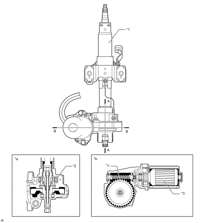
Text in Illustration *1 Steering Column Assembly *2 Torque Sensor *3 Power Steering Motor - - *a A-A Cross Section *b B-B Cross Section *c Reduction Mechanism - - -
The torque sensor with Hall ICs is used.
-
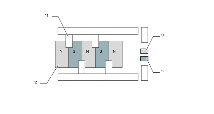
The torque sensor is built into the steering column. A multipole magnet is mounted to the input shaft, and a yoke is mounted to the output shaft. The input and output shafts are joined by the torsion bar.
-
The magnetic convergence ring assembly contains Hall ICs, which face opposite to each other. The system detects the steering direction in accordance with the direction of the magnetic flux that the amount of change in the magnetic flux density based on the relative displacement of the multipole magnet and the yoke. The power steering ECU assembly monitors the torque sensor signals that are output by the two Hall ICs to detect malfunctions.
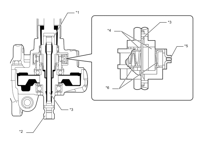
Text in Illustration *1 Input Shaft *2 Output Shaft *3 Torsion Bar *4 Multipole Magnet *5 Hall IC *6 Yoke 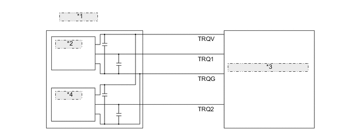
*1 TORQUE SENSOR *2 Hall IC 1 *3 POWER STEERING ECU ASSEMBLY *4 Hall IC 2 Note
After replacing the steering column assembly, the steering gear assembly or the power steering ECU assembly, calibration of the torque sensor zero point is required. For details, refer to the Repair Manual.
-
A low inertia, low noise, and high power output power steering motor is used.
-
The power steering motor consists of a rotor, stator and motor shaft.
-
The torque that is generated by the power steering motor is transmitted via the joint to the reduction mechanism.
-
The reduction mechanism reduces the speed of the power steering motor via the worm gear and the wheel gear, and transmits it to the column shaft.
-
The wheel gear is made of a high strength, low friction, and low wear plastic material, to realize low noise and a lightweight construction.
-
The worm gear is supported by the ball bearings in order to reduce noise and frictions.
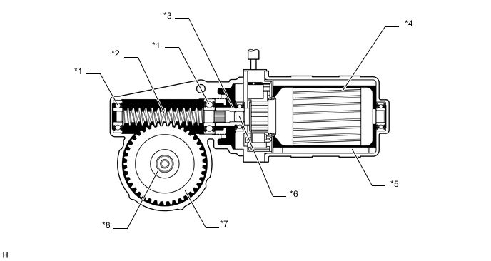
Text in Illustration *1 Ball Bearing *2 Worm Gear *3 Joint *4 Rotor *5 Stator *6 Motor Shaft *7 Wheel Gear *8 Column Shaft
-
-
-
OPERATION
-
Straightline Driving
-
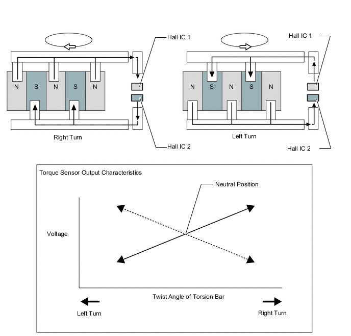
If the vehicle is driven straight and the driver does not turn the steering wheel, the yoke is located in the center between the N and S poles of the multipole magnet. Thus, no magnetic flux passes between the Hall ICs. In this case, the Hole ICs output a specified voltage to the power steering ECU assembly, to indicate that the steering wheel is in the neutral position. Therefore, it does not apply current to the motor.
Text in Illustration *1 Yoke *2 Multipole Magnet *3 Hall IC 1 *4 Hall IC 2
-
-
When Steering
-
When a driver turns the steering wheel to the right or left, the twist that is created in the torsion bar creates a relative displacement between the multipole magnet and the yoke.
-
At this time, the magnetic flux from the N to S pole of the multipole magnet passes between the Hall ICs. The system detects the steered direction of the steering wheel in accordance with the direction opposite to each other. As a result, the output characteristics of the 2 Hall ICs are constantly opposite each other. The system monitors the different outputs of these Hall ICs in order to detect malfunction.
-
The magnetic flux density becomes higher as it gets closer to the center of the respective pole. A Hall IC converts these magnetic flux fluctuations into voltage fluctuations, in order to transmit the turning torque of the steering wheel to the power steering ECU assembly.
-
The magnetic flux density becomes higher as it gets closer to the center of the respective pole. A Hall IC converts these magnetic flux fluctuations into voltage fluctuations, in order to transmit the turning torque of the steering wheel to the power steering ECU assembly.
-
-
-
FAIL-SAFE
-
Fail-safe operation modes are as follows:
Item Control Torque Sensor System Malfunction Disables the assist or limits the assist force. Power Steering Motor Overheating Power Steering Motor Short (including drive system malfunction) Power Steering Motor Overcurrent Power Steering ECU Overheating Power Steering ECU System Malfunction Vehicle Speed Signal and Engine Speed Signal Malfunction Pauses the assist. (Provides normal assist after the signal recovers.) Power Supply Voltage Malfunction Pauses the assist. (Provides normal assist after the voltage recovers.)
-
-
DIAGNOSIS
-
The power steering ECU assembly will also store a Diagnostic Trouble Code (DTC). The DTC can be accessed through the use of an intelligent tester. For details, refer to the Repair Manual.
-