CVT SYSTEM
-
FUNCTION OF MAIN COMPONENTS
-
The main components of the K411 CVT system are as follows:
Component Function Shift Solenoid Valve DS1 Controls the fluid flow volume to the primary pulley in accordance with the vehicle speed and accelerator pedal position (speed control during acceleration). Shift Solenoid Valve DS2 Shift Solenoid Valve SLT
-
Controls the line pressure.
-
Controls the engagement oil pressure of the forward clutch and reverse brake.
Shift Solenoid Valve SLU Controls the engagement oil pressure of the lock-up clutch. Shift Solenoid Valve SLS
-
Controls the oil pressure of the secondary pulley.
-
Controls the line pressure upon engagement of the forward clutch and reverse brake.
Transmission Revolution Sensor (NIN) Detects the primary pulley speed (input speed). Transmission Revolution Sensor (NOUT) Detects the secondary pulley speed (output speed). Transmission Revolution Sensor (NT) Detects the forward clutch drum speed. CVT Fluid Temperature Sensor Detects the CVT fluid temperature. Oil Pressure Sensor Detects the steel belt clamping force. E.F.I. Engine Coolant Temperature Sensor Detects the engine coolant temperature. Throttle Position Sensor Detects the opening angle of the throttle valve. Stop Light Switch Assembly Detects the brake pedal depressing signal. Park/Neutral Position Switch Assembly Detects the shift lever position. Transmission Control Switch
-
Detects that the shift lever is in M.
-
Detects the driver's shift-up and shift-down operations when the shift lever is in M.
Shift Paddle Switch (Transmission Shift Switch Assembly) Detects the driver's upshift or downshift request. Pattern Select Switch Assembly Detects that the driving mode is in the sport mode. Shift Position and Shift Range Indicator Indicates the shift lever position and shift range. Sport Mode Indicator Illuminates when the pattern select switch assembly is pressed and informs the driver that sport mode is active. MIL Illuminates or blinks to alert the driver that the ECM has detected a malfunction. Buzzer Sounds when shift-down operation is rejected in M mode. ECM
-
Controls the electronic control of the CVT system.
-
When the ECM detects a malfunction, the ECM makes a diagnosis and memorizes the failed section.
Yaw Rate and Acceleration Sensor*1 Detects the angle of inclination of the vehicle Engine Stop and Start ECU*2 Sends signals to each control computer to perform the engine start and stop control and the slope start assistant control. Eco Run Vehicle Converter Assembly*2 Supplies battery voltage to the oil pump motor assembly. Oil Pump Motor Assembly*2 Maintains CVT oil pressure during idle stop. It also contains the oil pump motor driver. Oil Pump Motor Driver*2 Controls the output of the oil pump motor assembly. Skid Control ECU
-
Transmits the vehicle speed and the longitudinal acceleration signal to the ECM.
-
Transmits the operating states of the ABS and VSC to the ECM.
Air Conditioning Amplifier Assembly*3 Transmits the operating state of the air conditioning system to the ECM. Certification ECU (Smart Key ECU Assembly) *4 Receives shift lever position signals from the part/neutral position switch assembly and transmits those signals to the ECM. *1: Models with ABS with EBD, Brake Assist, TRC and VSC
*2: Models with stop and start system
*3: Models with air conditioning system
*4: Models with entry and start system
-
-
The main components of the shift lock system are as follows:
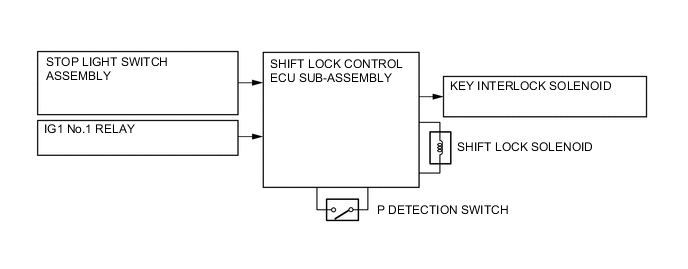
Component Function Shift Lock Control Unit Shift Lock Solenoid Locks the shift lever in P. P Detection Switch Detects if the shift lever is in P. Stop Light Switch Assembly Detects in the brake pedal is depressed. Key Interlock Solenoid* Prevents the from being pulled out in any position other than in P. Shift Lock Control ECU Sub-assembly Controls the shift lock solenoid and the key interlock solenoid based on signals from each switch. *: Models without entry and start system
-
-
SYSTEM CONTROL
-
Control List
-
The electronic control system of the K411 CVT consists of the controls listed below.
Control Outline Engine - CVT Integrated Control Effects coordinate control of the CVT system and engine control system to ensure both smooth and powerful driving that excels in shift response and fuel economy. Pulley Ratio Control Automatic Shift Control Optimally controls the pulley ratio and shifting speed to suit the driver's intentions and driving conditions based on signals from various sensors and switches. Acceleration Improvement Control 7-speed Sport Sequential Shiftmatic with Shift Paddle Switch Neutral Control When the vehicle is stopped, shut off the driving force to the transaxle to improve fuel economy. Shift Control in Uphill/Downhill Traveling Controls to restrict the upshift or to provide appropriate engine braking by using the ECM to determine whether the vehicle is traveling uphill or downhill. Lock-up and Flex Lock-up Control The ECM sends a current to shift solenoid valve SLU based on the throttle position sensor signal and vehicle speed signal, and engages or disengages the lock-up clutch. Oil Pump Motor Assembly Control Controls the oil pump motor to regulate the oil pressure to the optimum level so that the vehicle can start off smoothly.
-
-
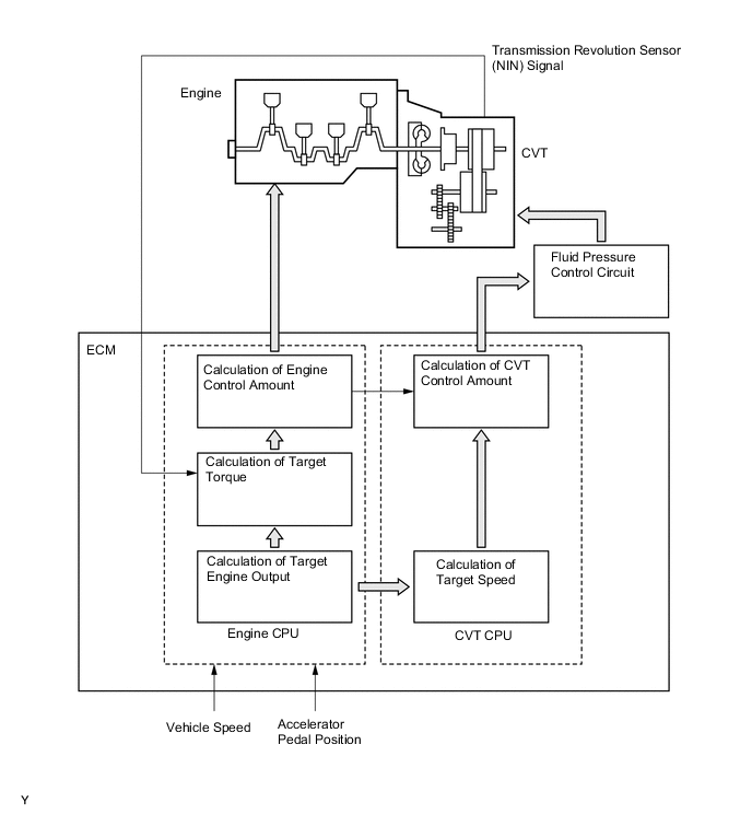
Engine - CVT Integrated Control
-
To effect fine-tuned control in accordance with driving conditions, various signals are exchanged between the engine control system and the CVT system. As a result, both smooth and powerful driving that excels in shift response and fuel economy has been achieved.
-
-
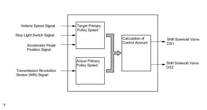
Pulley Ratio Control
-
The ECM calculates the target primary pulley speed in accordance with the accelerator pedal position signal, vehicle speed signal, and stop light switch signal, in order to attain an optimal pulley ratio and shifting speed. To allow the actual primary pulley speed (acquired from the primary speed sensor) to match the target primary pulley speed, the ECM actuates shift solenoid valves DS1 and DS2 in order to control the inflow and outflow volume of line pressure to and from the primary pulley. As a result, optimal pulley ratio and shifting speed have been achieved.
-
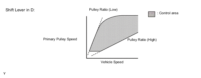
When the shift lever is in D, the system effects engine integrated control to optimize fuel economy characteristics and driving performance.
-
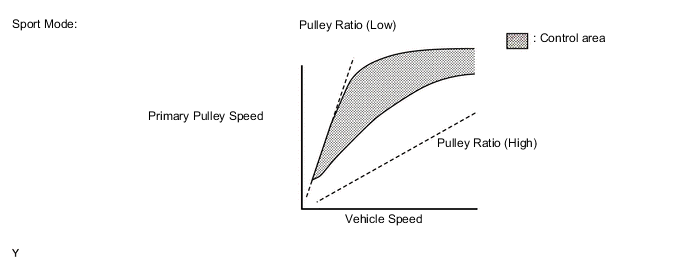
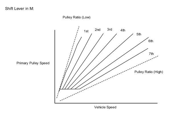
The sport mode limits the shift range for the acceleration side and maintains the primary pulley speed at high speeds. This produces a moderate engine braking force and provides an excellent shift response.
-
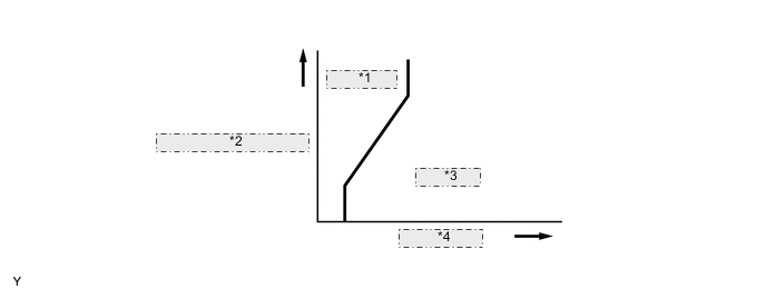
When the shift lever is in M, the shift characteristic is as shown below. The system will upshift automatically when the vehicle reaches the set speed during acceleration.
-
The system determines the driver's acceleration request based on the vehicle speed and the changes in the accelerator pedal position. When the system determines this request, it will change the shift characteristic into one in which the engine speed and vehicle speed increase linearly. This improves the acceleration feeling.
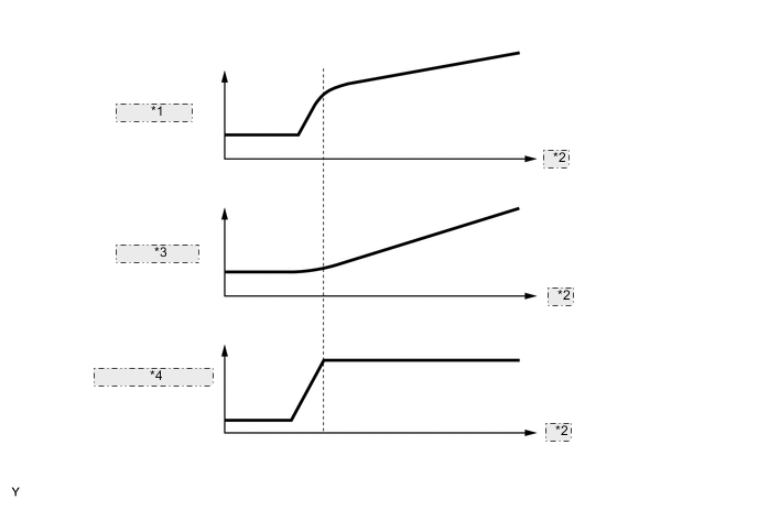
*1 Engine Speed *2 Time *3 Vehicle Speed *4 Accelerator Pedal Depressed Angle
-
-
Neutral Control
-
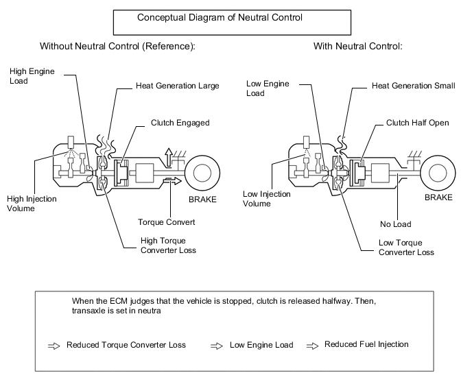
While the vehicle is stopped with the shift lever in D, by disconnecting the engine and CVT (release the forward clutch halfway), engine load is reduced. This improves fuel economy.
-
-
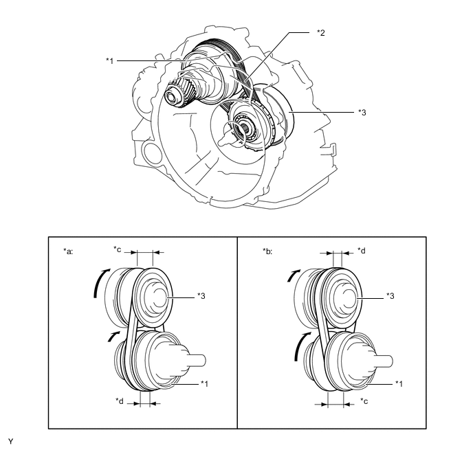
Shift Control in Uphill/Downhill Traveling
-
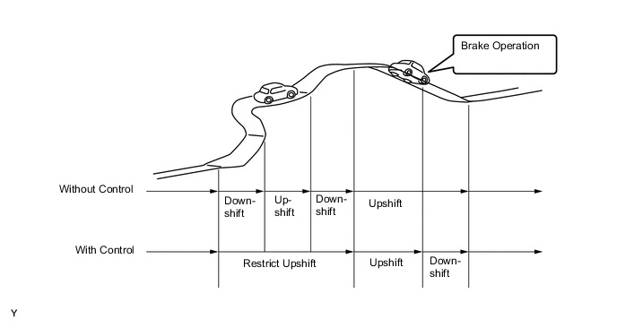
The ECM determines that the vehicle is driving uphill or downhill based on the accelerator pedal position sensor signal and the vehicle speed signal. During uphill driving, it limits upshift to achieve smooth driving. During downhill driving, it downshifts upon detecting brake pedal operation, in order to provide moderate engine braking.
-
The actual acceleration calculated from the vehicle speed signal is compared with the reference acceleration (based on level road travel) stored in the ECM to determine uphill or downhill travel.
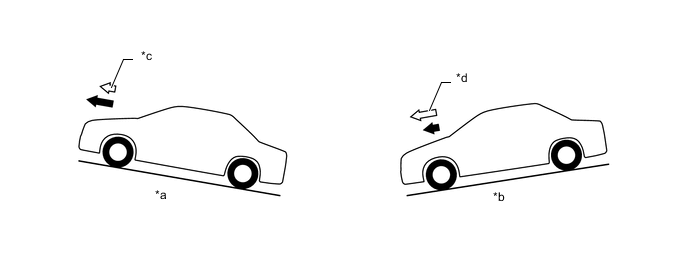
Text in Illustration *a Uphill *b Downhill *c Smaller *d Greater 
Referance acceleration 
Actual acceleration
-
-
Lock-up Control
-
The lock-up operation range has been expanded from that of the previous automatic transaxle, thus enabling control to start from low speeds.
-
The lock-up operation range during deceleration has been expanded to the low-speed range. This expands the fuel cut range and achieves excellent fuel economy.
*1 Lock-up Off *2 Throttle Opening Angle *3 Lock-up On *4 Vehicle Speed
-
-
Flex lock-up Control
-
In order to improve the transmission efficiency and also the fuel economy, the duty solenoid (SLU) for lock-up engagement pressure control is employed to deliver flex lock-up control that can provide more precise control than that of the conventional lock-up clutch mehcanism.
-
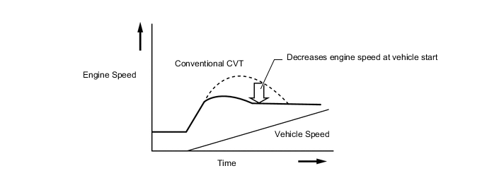
The flex lock-up control consists of flex start control and flex lock-up control at deceleration.
-
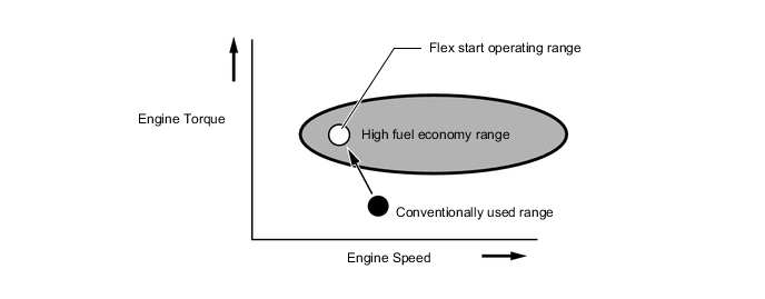
The flex start control aggressively operates the lock-up clutch during start-off to increase the transmission efficiency, as a result, the engine can run in its most efficient operating range.
-
The flex lock-up control at deceleration is used to expand the fuel-cut range. It operates the lock-up clutch over the low vehicle speed range when the vehicle decelerates so that minimal speed difference between the engine speed and turbine speed can be maintained.
-
-
Oil Pump Motor Assembly Control (Models with Stop and Start System)
-
Because the engine stop and start ECU operates the oil pump motor assembly during idle stop, the CVT oil pressure is secured, enabling a smooth vehicle start.
-
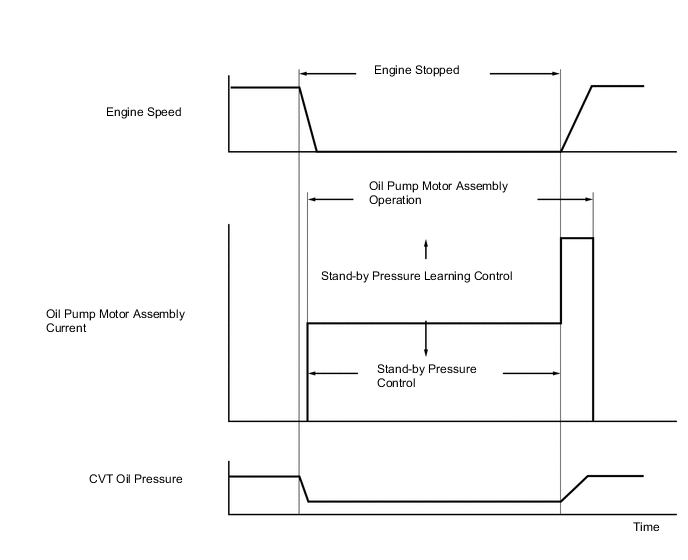
The oil pump motor assembly control consists of oil pump motor assembly operation control, optimal stand-by pressure control and stand-by pressure learning control.
-
Oil pump motor assembly operation control actuates a CVT oil pump motor when it receives an engine stop signal. The CVT oil pump motor will stop operating either when the engine automatically starts and the engine speed exceeds a specified value, or when driving force is generated.
Oil pump motor assembly operation (O: Operating, X: Not operating, -: Idle stop is disabled) Shift Position P R N D M Brake On (applied) ○ - ○ ○ -*2 Brake Off (not applied) X*1 - X*1 - -*2 Tech Tips
*1: Operates for a certain period of time after the vehicle is stopped, and then stops.
*2: When the vehicle was stopped with the shift lever in the D position, and then the lever was changed to the M position after idle stop had engaged, the idle stop and the oil pump motor assembly continue to operate.
Oil pump motor assembly operating condition item Condition Remarks CVT Oil Temperature 25 to 100 [°C] Detected from the oil temperature sensor in the CVT -
Stand-by pressure learning control maintains the oil pressure generated by the CVT oil pump motor at the appropriate level while the engine idling is stopped. In order to ensure good start-off response when the vehicle restarts from the idle stop status, this control regulates the oil pressure to an optimum level during stand-by mode to save electrical power, improving the fuel efficiency and also providing the reliability. Furthermore, it ensures responsiveness when the engine restarts automatically by increasing the oil pressure.
-
Stand-by pressure learning control is a learning control for optimizing oil pressure levels using the CVT oil pump motor while the vehicle is in the idling stop state.
-
Continual operation prohibition control prohibits continual and longtime operation of the oil pump motor assembly to ensure reliability.
-
-
-
FUNCTION
-
7-speed Sport Sequential Shiftmatic with Shift Paddle Switch (Transmission Shift Switch Assembly)
-
The driver can select the desired shift range by moving the shift lever to "+" (forwards) or to "-" (backwards) while shift lever is in M (M mode). Also, the shift paddle switch (transmission shift switch assembly) is used, which enable changing the shift range while the driver is holding the steering wheel. Thus, the driver is able to shift gears with a manual-like feel.
-
When the shift lever is in D (D mode), the driver can momentarily select a desired shift range (M mode) by operating the shift paddle switch (transmission shift switch assembly). Automatic shifting (D mode) will be reinstated under the following conditions:
-
The driver continues to push the shift paddle switch (transmission shift switch assembly) in the "+" direction longer than a predetermined length of time.
-
The driver depresses the accelerator pedal longer than a predetermined length of time while the transmission remains in the same shift range.
-
The vehicle has stopped.
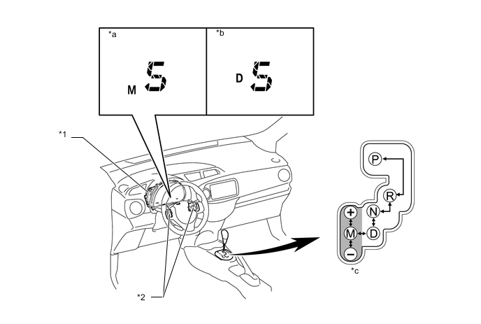
Text in Illustration *1 Combination Meter Assembly *2 Shift Paddle Switch (Transmission Shift Switch Assembly) *a 5th in M Mode *b 5th in D Mode *c M Mode - - -
-
In M mode, the transmission automatically upshifts or downshifts under the following conditions:
Condition System Control Engine is under-revving. 1 step downshift Engine is Over-revving. 1 step upshift -
The ECM will restrict the changing of the shift range if it detects a malfunction in the CVT system.
-
If the vehicle speed and engine speed exceeds or goes below a preset level in response to the driver's downshift operation request, changing the shift range will be prohibited. In this case, the buzzer in the combination meter assembly will sound to alert the driver.
-
-
Shift Lock System
-
A shift lock system consisting of a key interlock device* and a shift lock mechanism is used.
-
On the models without the entry and start system, the key interlock device prevents the key from being pulled out after the ignition switch is turned off, unless the shift lever is moved to P. Thus, the driver is urged to park the vehicle with the shift lever in P.
-
The shift lock mechanism prevents the shift lever from being moved to a position other than P, unless the ignition switch is turned to ON, and brake pedal is depressed. It prevents the vehicle from starting off suddenly.
-
The shift lock control ECU sub-assembly uses the P detection switch to detect the shift lever position, and receives input signals from the stop light switch and ignition switch. Upon receiving these signals, the shift lock control ECU sub-assembly turns on the shift lock solenoid and the key interlock solenoid* in order to release the shift lock and key interlock*.
-
A shift lock release button, vehicle manually overrides the shift lock mechanism, is used.
-
*: Models without entry and start system
-
-
-
-
CONSTRUCTION
-
Torque Converter Assembly
-
A compact, lightweight and high-capacity torque converter is used.
-
A damper structure, which can perform a lock-up operation starting with the low-speed range, is used. This absorbs engine torque fluctuations and provides excellent ride comfort.
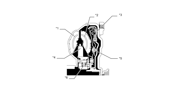
Text in Illustration *1 Pump Impeller *2 Turbine Runner *3 Lock-up Clutch *4 Stator *5 Damper *6 1-way Clutch
-
-
Oil Pump Assembly
-
The trochoid gear type oil pump is used.
-
The oil pump assembly is operated by the torque converter. It lubricates the planetary gear units and supplies operating fluid pressure to the hydraulic control.
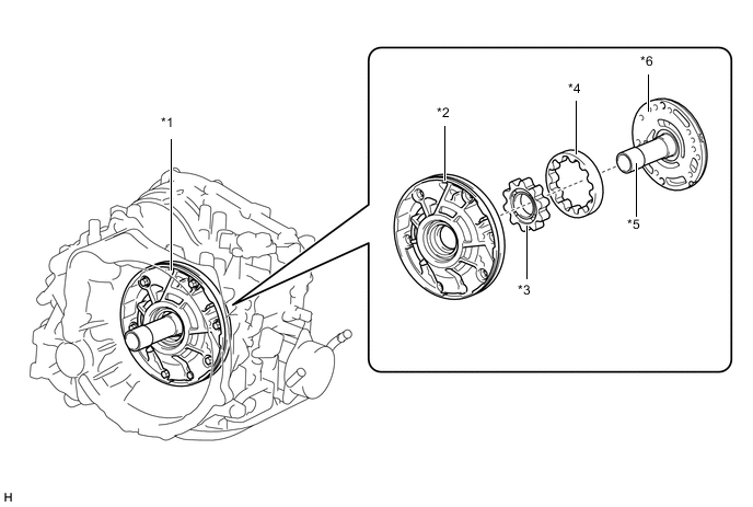
Text in Illustration *1 Oil Pump Assembly *2 Oil Pump Body *3 Front Oil Pump Drive Gear *4 Front Oil Pump Driven Gear *5 Stator Shaft *6 Pump Cover
-
-
Forward/Reverse Switching Unit
-
The forward/reverse switching unit consists of a planetary gear, a forward clutch, and a reverse brake.
-
The forward clutch, which acts during a forward movement, connects the input shaft with the planetary carrier.
-
The reverse brake, which acts during a reverse movement, keeps the ring gear stationary.
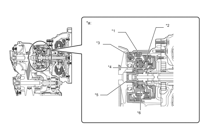
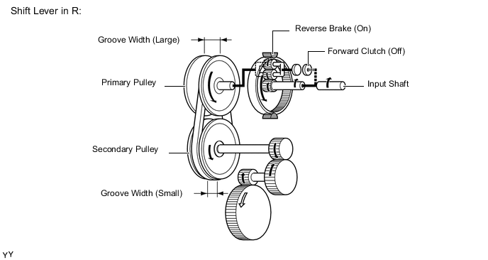
Text in Illustration *1 Reverse Brake *2 Forward Clutch *3 Ring Gear *4 Double Pinion Type Planetary Gear *5 Planetary Carrier *6 Sun Gear *a Forward/Reverse Switching Unit - -
-
-
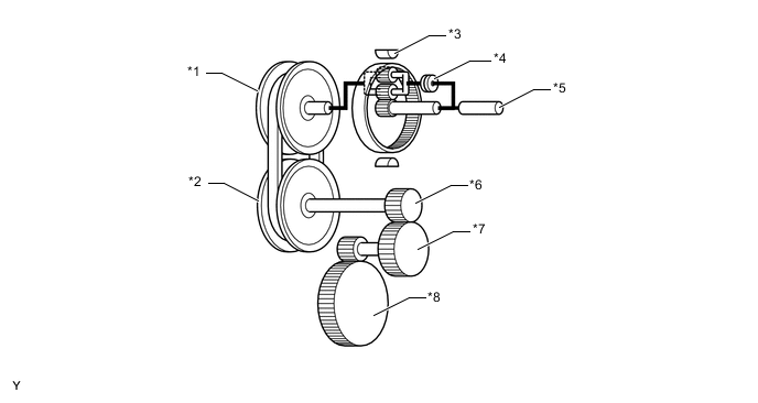
Pulley and Steel Belt Unit
-
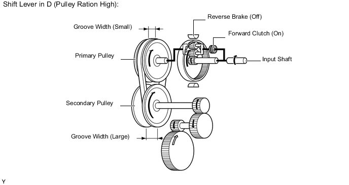
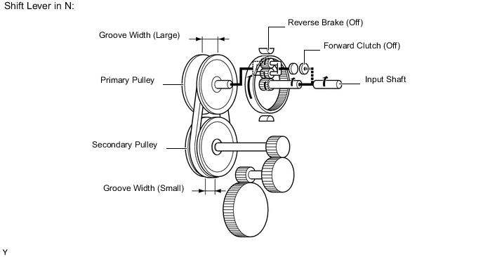
The widths of the grooves of the pulleys are changed through hydraulic control.
-
During acceleration, the action of shift solenoid valve DS1 increases the fluid inflow volume to the primary pulley, thus narrowing the width of the pulley groove.
-
During deceleration, the action of shift solenoid valve DS2 increases the fluid outflow volume to the primary pulley, thus widening the width of the pulley groove.
-
The secondary pulley is hydraulically controlled by the shift solenoid valve SLS. It controls the belt clamping pressure to ensure the proper power transmission efficiency.
Text in Illustration *1 Secondary Pulley *2 Steel Belt *3 Primary Pulley - - *a Pulley Ratio (Low) *b Pulley Ratio (High) *c Groove Width (Large) *d Groove Width (Small) -
The primary pulley uses a single piston construction.
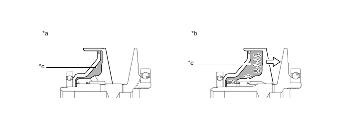
Text in Illustration *a Pulley Ratio (Low) *b Pulley Ratio (High) *c Chamber - - -
The steel belt consists of elements and 2 rows of steel rings. In contrast to the chains and V-belts that transmit power through the use of tensile force, the steel belt uses the compressive action (pushing force) of the elements to transmit power.
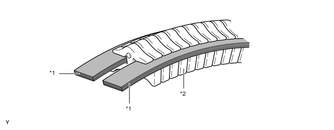
Text in Illustration *1 Steel Ring *2 Element
-
-
Reduction Gear and Differential
-
The reduction gear reduces the power output from the secondary pulley and transmits it to the differential.
-
A 2 pinion type differential is used.
Text in Illustration *1 Reduction Drive Gear *2 Reduction Driven Gear *3 Front Differential - -
-
-
Parking Lock Mechanism
-
A parking lock mechanism is used on the secondary pulley. The engagement of the parking lock pawl with the parking lock gear integrated with the secondary pulley locks the movement of the vehicle.
Text in Illustration *1 Parking Lock Pawl *2 Parking Lock Gear
-
-
Transmission Oil Cooler
-
The transmission oil cooler uses engine coolant to warm up the CVT fluid quickly. Consequently, the friction losses of the CVT are quickly reduced, thus improving fuel economy.
-
After warming up the CVT fluid, the engine coolant flows into the transmission oil cooler to cool down the CVT fluid.
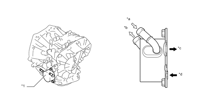
Text in Illustration *1 Transmission Oil Cooler - - *a Engine Coolant Inlet *b Engine Coolant Outlet *c CVT Fluid Outlet *d CVT Fluid Inlet CVT Fluid Flow CVT Coolant Flow
-
-
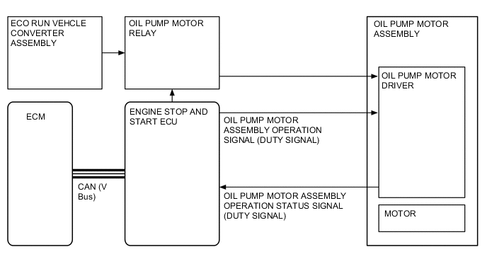
Oil Pump Motor Assembly (Models with Stop and Start System)
-
The exclusively used oil pump motor assembly has been provided for the vehicles with the stop and start system and is installed on the front of the CVT case. This enables a stable CVT fluid supply at the time of idle stop, and delivers good responsiveness without any uncomfortable feel, and smooth drivability, at the time of vehicle start from the engine stopped status.
-
By integrating the oil pump motor driver into the oil pump motor assembly, a small-sized and weight reduced system has been achieved.
-
The oil pump motor assembly provided for the vehicles with the stop and start system is controlled by the engine stop and start ECU.
-
The configuration and operations of the parts other than the oil pump motor assembly are the same as the vehicles without the stop and start system.
Tech Tips
The oil pump motor assembly only operates when the engine is in the idle stop status. While the engine is operating, CVT fluid is supplied from the regular oil pump assembly.
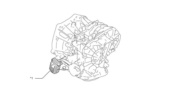
Text in Illustration *1 Oil Pump Motor Assembly - - -
The oil pump motor assembly consists of oil pump motor driver section, DC sensorless and brushless motor section, and oil pump section.
-
A cycloid type oil pump has been used for the oil pump section to provide a stable oil supply.
-
The oil pump motor driver controls the oil pump motor assembly operations according to the signals (duty signals) from the engine stop and start ECU.
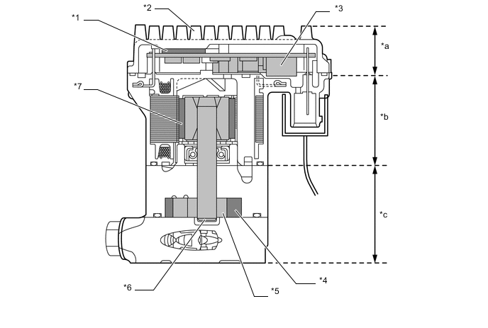
Text in Illustration *1 Radiator Sheet *2 Radiator Fin *3 Oil Pump Motor Driver *4 Driven Rotor *5 Drive Rotor *6 Shaft *7 Magnet - - *a Oil Pump Motor Driver Section *b DC Sensorless and Brushless Motor Section *c Oil Pump Section - -
-
-
Transmission Valve Body Assembly
-
The transmission valve body assembly consists of the upper and lower valve bodies and 5 shift solenoid valves.
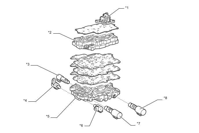
Text in Illustration *1 Rear Upper Valve Body *2 Upper Valve Body *3 Shift Solenoid Valve SLU *4 Shift Solenoid Valve DS2 *5 Lower Valve Body *6 Shift Solenoid Valve DS1 *7 Shift Solenoid Valve SLT *8 Shift Solenoid Valve SLS -
To ensure the proper control of the belt clamping pressure necessary for transmitting torque, the system controls the hydraulic pressure applied to the secondary pulley. The transmission valve body assembly is provided with a dedicated hydraulic pressure circuit for belt clamping pressure control. This circuit optimally controls the hydraulic pressure applied to the secondary pulley, thus achieving superior torque transmission performance.
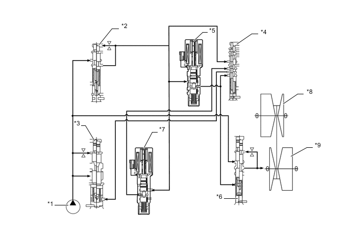
Text in Illustration *1 Oil Pump Assembly *2 No. 2 Line Pressure Modulator Valve *3 Primary Regulator Valve *4 Clutch Apply Control Valve *5 Shift Solenoid Valve SLS *6 No. 1 Line Pressure Modulator Valve *7 Shift Solenoid Valve SLT *8 Primary Pulley *9 Secondary Pulley - - -
Pulley ratio control is effected by controlling the inflow and outflow of the CVT fluid to and from the primary pulley. Separate hydraulic circuits are provided for acceleration (fluid inflow) and deceleration (fluid outflow) in order to provide fine-tuned control and a high level of reliability.
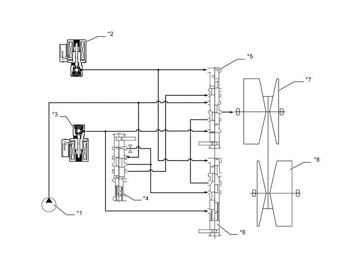
Text in Illustration *1 Oil Pump Assembly *2 Shift Solenoid Valve DS2 *3 Shift Solenoid Valve DS1 *4 Bypass Valve *5 No. 1 Ratio Control Valve (Acceleration Control) *6 No. 2 Ratio Control Valve (Deceleration Control) *7 Primary Pulley *8 Secondary Pulley
-
-
Shift Solenoid Valves DS1 and DS2
-
The functions of each solenoid valve are outlined in the table below.
Shift Solenoid Valve Type Function DS1 3-way Acceleration control by increasing the fluid flow volume to the primary pulley DS2 3-way Deceleration control by increasing the fluid flow volume from the primary pulley 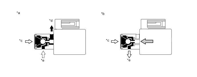
Text in Illustration *a Off Condition *b On Condition *c Line Pressure *d Drain *e Control Pressure - -
-
-
Shift Solenoid Valves SLS, SLT and SLU
-
The functions of each solenoid valve are outlined in the table below.
Shift Solenoid Valve Type Function SLS Linear Control of hydraulic pressure applied to the secondary pulley in order to control the belt clamping pressure necessary for transmitting torque SLT Linear
-
line pressure control
-
Precise control in accordance with the variation of the pulley ratio using a linear solenoid valve
SLU Linear lock-up clutch pressure control 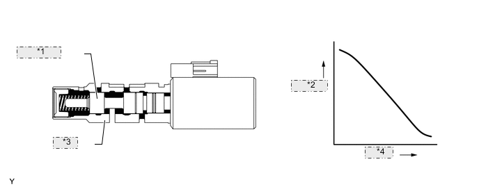
SHIFT SOLENOID VALVE SLS *1 SPOOL VALVE *2 Hydraulic *3 SLEEVE *4 Current 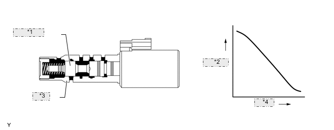
SHIFT SOLENOID VALVE SLT *1 SPOOL VALVE *2 Hydraulic *3 SLEEVE *4 Current 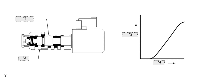
SHIFT SOLENOID VALVE SLU *1 SPOOL VALVE *2 Hydraulic *3 SLEEVE *4 Current -
-
-
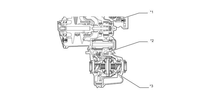
Transmission Revolution Sensors and Oil Pressure Sensor
-
The transmission revolution sensor (NIN) detects the input shaft speed and participates in shift control.
-
The transmission revolution sensor (NOUT) detects the output shaft speed and participates in shift control.
-
The transmission revolution sensor (NT) detects the forward clutch turbine speed and participates in lock-up clutch pressure control and forward clutch pressure control.
-
The oil pressure sensor detects the hydraulic pressure applied to the secondary pulley and participates in belt clamping pressure control, which optimally controls the clamping pressure of the steel belt necessary for transmitting torque.
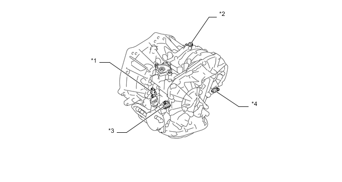
Text in Illustration *1 Transmission Revolution Sensor (NT) *2 Transmission Revolution Sensor (NOUT) *3 Transmission Revolution Sensor (NIN) *4 Oil Pressure Sensor
-
-
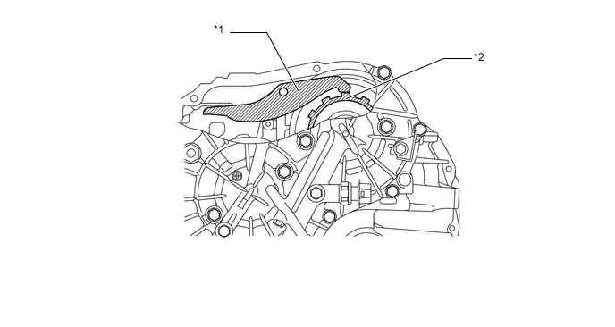
CVT Fluid Temperature Sensor
-
Detects the fluid temperature, effects shift control in accordance with the fluid temperature, and participates in lock-up clutch pressure control, forward clutch pressure control, and belt clamping pressure control.
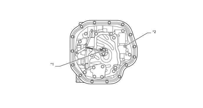
Text in Illustration *1 CVT Fluid Temperature Sensor *2 Transmission Valve Body Assembly
-
-
Shift Control Mechanism
-
A gate type shift lever that uses a transmission control cable is used.
-
The shift control mechanism consists of a shift lock control unit assembly and a transmission control cable assembly.
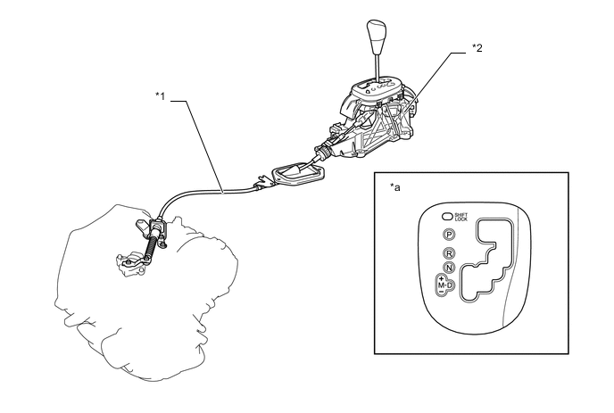
Text in Illustration *1 Transmission Control Cable Assembly *2 Shift Lock Control Unit Assembly *a Shift Pattern - -
-
-
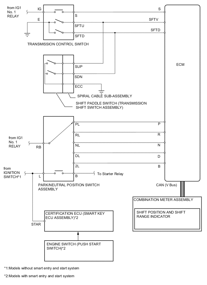
Park/Neutral Position Switch Assembly, Transmission Control Switch and Shift Paddle Switch (Transmission Shift Switch Assembly)
-
The park/neutral position switch assembly sends the P, R, N, D and M position signals to the ECM.
-
The transmission control switch detects whether the shift lever is in D or M, and detects the operating conditions of the shift lever ["+" (forwards) or "-" (backwards)] when the M mode is selected, and sends signals to the ECM.
-
The shift paddle switch (transmission shift switch assembly) is installed in the steering wheel. The ECM detects the operation of the shift paddle switch (transmission shift switch assembly) ["+" (right side) or "-" (left side)] when the M mode is selected.
-
The ECM controls the CVT system in accordance with the shift lever position signals.
-
The ECM transmits signals to the combination meter assembly for the shift position and shift range indicator (P, R, N, D and M) in response to the signals received from the switches.
-
-
-
OPERATION
-
Forward/Reverse Switching Unit
-
The forward clutch is connected when advancing, and engine torque is input from the input shaft to the planetary carrier and is output to the primary pulley.
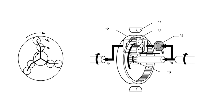
Text in Illustration *1 Reverse Brake *2 Ring Gear *3 No. 2 Pinion Gear *4 Forward Clutch *5 No. 1 Pinion Gear *6 Sun Gear *a Input *b Output -
Engine torque is input to the sun gear when reversing. The ring gear is fixed by the reverse brake to transmit engine torque to the stepless shift transmission mechanism with inverse rotation.
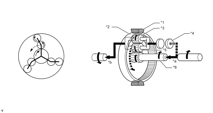
Text in Illustration *1 Reverse Brake *2 Ring Gear *3 No. 2 Pinion Gear *4 Forward Clutch *5 No. 1 Pinion Gear *6 Sun Gear *a Input *b Output
-
-
CVT Power Flow
-
The changing of the pulley ratio is accomplished in a continuously variable manner by varying the widths of the grooves of the primary and secondary pulleys.
Text in Illustration *1 Primary Pulley *2 Secondary Pulley *3 Reverse Brake *4 Forward Clutch *5 Input Shaft *6 Reduction Drive Gear *7 Reduction Driven Gear *8 Differential Ring Gear 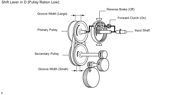
-
-
Oil Pump Motor Assembly
-
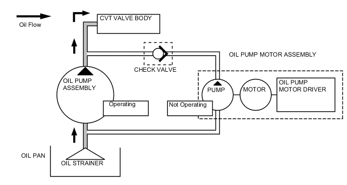
The oil pump assembly in the CVT, which is powered by the engine, generates oil pressure. At this time, the oil pressure to be applied to the oil pump motor assembly is blocked by the check valve installed in the discharge section of the oil pump motor assembly. The oil pump motor assembly is not operating at this time.
-
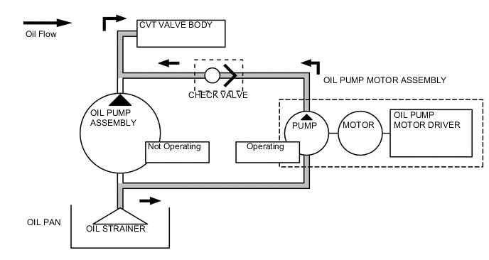
During idle stop operation, the oil pump assembly operation is stopped. At this time, the oil pump motor assembly operates according to the signals sent from the oil pump motor driver and generates oil pressure to open the check valve and supply oil pressure to the CVT valve body.
-
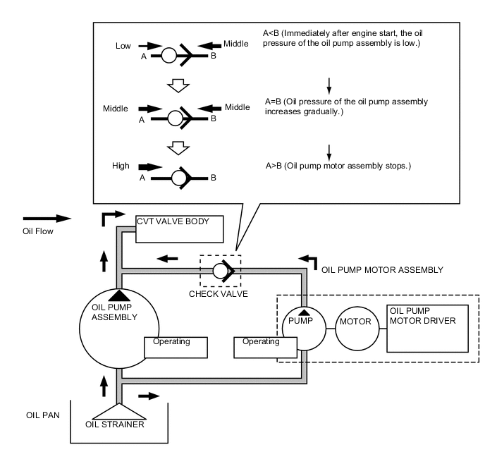
During engine automatic start operation, oil pressure generated by both the oil pump motor assembly and the oil pump assembly is applied to the system. When the oil pressure generated from the oil pump assembly exceeds the oil pressure generated from the oil pump motor assembly, the check valve closes and the oil pressure generated from the oil pump motor assembly is no longer applied. The oil pump motor assembly stops according to signals such as engine speed.
-
-
-
FAIL-SAFE
-
This function minimizes the loss of operability when any abnormality occurs in any sensor or shift solenoid valve.
Malfunction Part Function Transmission Revolution Sensor (NIN) Calculates the input speed from the transmission revolution sensor (NT) signal and effects normal control. Transmission Revolution Sensor (NOUT) Calculates the output speed from the vehicle speed signal and effects normal control. Transmission Revolution Sensor (NT) Calculates the turbine speed from the transmission revolution sensor (NIN) signal and effects normal control. Shift Solenoid Valve DS1 During a shift solenoid valve DS1 malfunction, the current to the shift solenoid valve stops, causing the pulley ratio to lean more towards deceleration than normal. Shift Solenoid Valve DS2 During a shift solenoid valve DS2 malfunction, the current to the shift solenoid valve stops, causing the pulley ratio to lean more towards acceleration than normal. Shift Solenoid Valve SLT During a shift solenoid valve SLT malfunction, the current to the shift solenoid valve is stopped and the line pressure becomes equal to the maximum oil pressure. Shift Solenoid Valve SLU
-
During a shift solenoid valve SLU malfunction, the current to the shift solenoid valve is stopped.
-
The lock-up clutch is released.
Shift Solenoid Valve SLS During a shift solenoid valve SLS malfunction, the current to the shift solenoid valve is stopped and the belt clamping pressure is maintained by the line pressure. CVT Fluid Temperature Sensor During a CVT fluid temperature sensor malfunction, the ECM fixes the fluid temperature and effects normal control. Oil Pump Motor Assembly*
-
As for the oil pump motor assembly operation status, the ECM determines that there is a fail on the oil pump motor assembly by detecting the motor status whether it is rotating or not.
-
A fail of the oil pump motor assembly is stored in the diagnosis and prohibit the operation of the idle stop controls.
-
*: Models with stop and start system
-
-
-
DIAGNOSIS
-
When the ECM detects a malfunction, the ECM makes a diagnosis and memorizes the failed section. Furthermore, the MIL in the combination meter assembly illuminates or blinks to inform the driver.
-
At the same time, the Diagnostic Trouble Codes (DTCs) are stored in memory. The DTCs can be read by connecting an intelligent tester. For details, refer to the Repair Manual.
-